Example - UDIM texturing the Sugarcube character
 This example scene is in the 2018 content - UDIM_Sugarcube.
This tutorial was written while the procedural texture Grid could be shown in OpenGL. Advancements in our OpenGL display mean that we can now display many more things in OpenGL, but this isn't one of them.
As an example of using UDIMs to texture a character, we have chosen the Sugarcube from the Genoma examples.
We'll start by hiding everything we don't absolutely need:
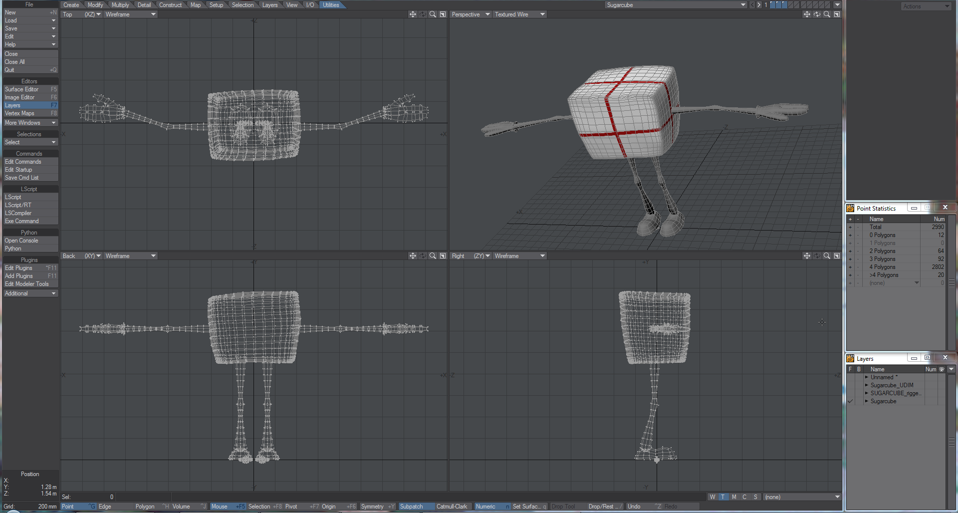
There are several versions of the Sugarcube character, some rigged and some not. If the version you use is rigged, the easiest way to hide the Skelegons used for rigging is to open the Statistics panel (W) while in Polygon selection mode and hit the + next to the Skelegons entry. Hit - on the keyboard to hide them once selected.
Select polys on the hands, arms legs and feet, then use Select Connected (]) to make sure everything is selected, then hide (-)
There might be some points unattached to anything in the feet area that can be deleted. Once done, hitting A should fill the viewport with the cube.- Now we have our cube front and center we can UV map it. Since we want to use UDIM tiles for our map, we are going to proceed slightly differently to a standard Atlas map. First, switch one viewport to UV. Then, with the front of the cube in view (the side facing +Z), select the four polygons in the center
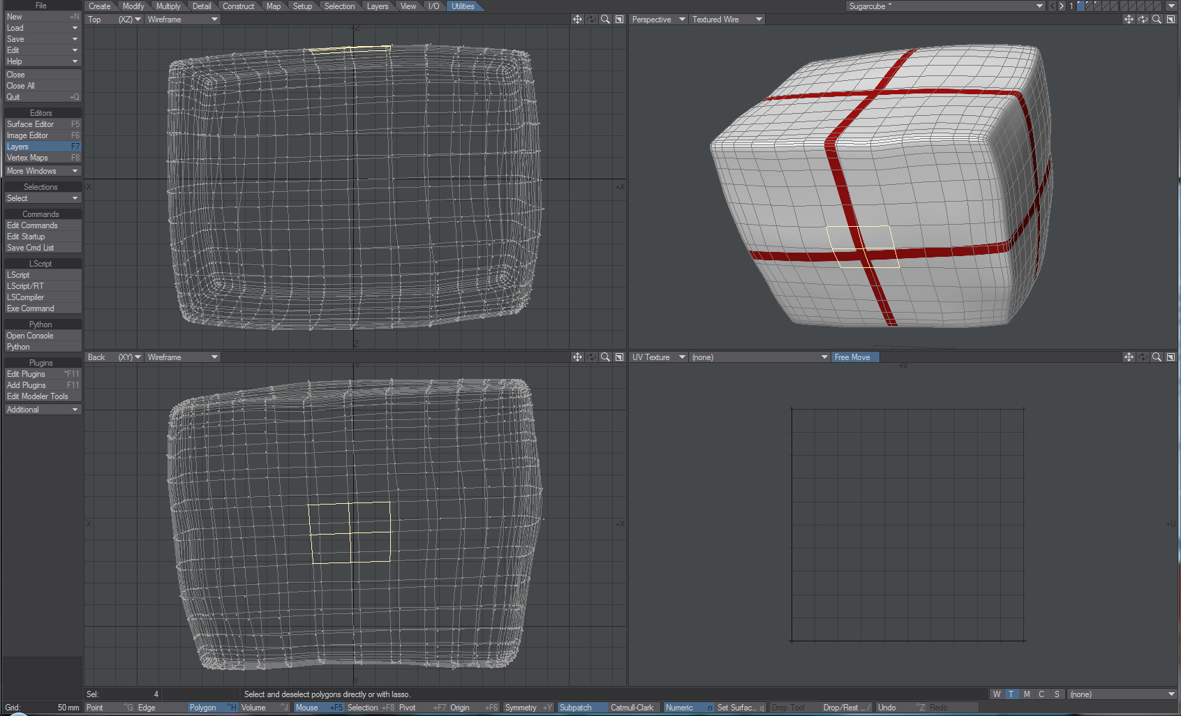
Use Selection > Modify Selection > Expand (}) to select the whole side (should be seven expands).
Cut the polygons from the cube (Ctrl-X) and paste them back (Ctrl-V) to separate the polygons and then we will start our UV map. Click the T under the bottom right viewport and select (new) from the dropdown menu. Doing so will open the following window: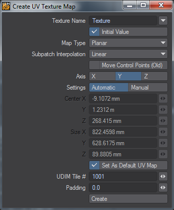
We want to leave the Map Type as Planar, but change the Axis to Z and at the bottom of the window, change the Padding to 0.05. Hit Create and we will start our UDIM UV map.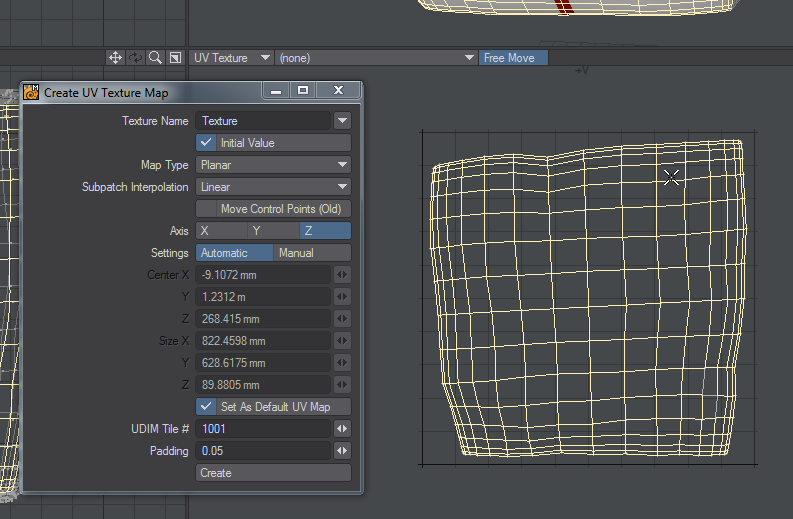
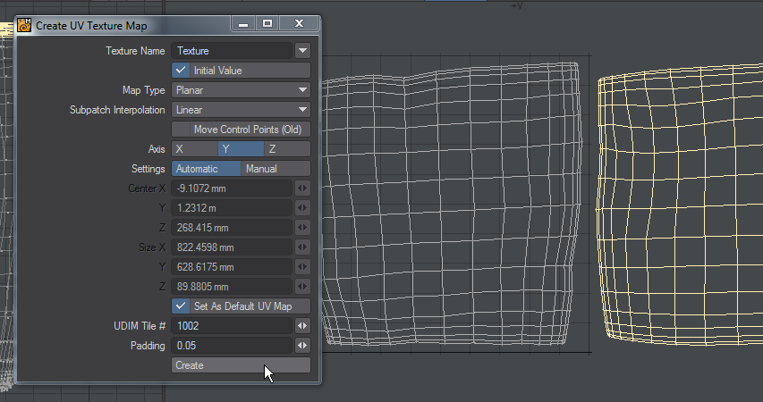
- We need to repeat the steps for the other sides of the cube. Do the top of the cube next, selecting the middle four polys and expanding the selection. Cut the selected poly and Paste them back in place, then choose the appropriate axis for the UV map. We keep the same Texture Name, but for each additional face of the cube we increment the UDIM Tile # at the bottom of the Create UV window.
- Proceed in this fashion from the most to the least important. I have chosen Front, Top, Left, Right, Back, Bottom for my order.
- Our UDIM UV map is complete. In order to map images to it, there are several choices. If we wish to use our UV map as a guide, you can Export an EPS (Save > Export > Export EPS) that can be opened in an image editing program as a basis for your textures. While the default Fit in Page works for standard UV maps, you will probably need to change to Fit to Scale if you have several UDIM tiles (a value of 0.33 works for me for this object).
For this example, I created six images. The original images are included in the content directory, but need to share a name and have a suffix relating to the UDIM tile they are for - my image for the front of the cube is named Color-1001.png. This naming refers to the use for the image (a color map) and the tile for which it is intended.
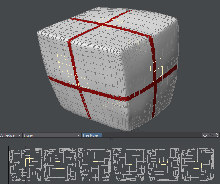
All that remains now is to use this UDIM sequence to map our cube - Open the Surface Editor (F5) and choose the SUGAR_BODY surface. It already has a texture map (the red cross that has helped use locate the center of each face for our selections), and we'll use it for our image map. First in Layers:
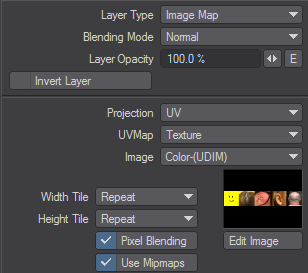
- Click the T and change the Layer Type to Image Map. Set the Projection to UV, choose the UVMap, and the Image as shown:
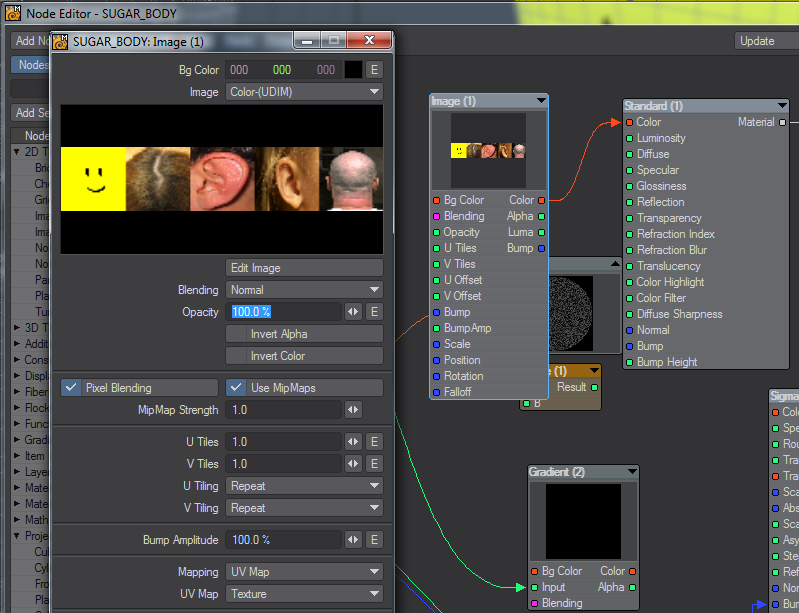
- To add the Texture map nodally, double click on the surface name to open the Node Editor. Because this is an old asset, the node network is a bit messy, but all we are concerned with is adding an Image node and hooking its Color output to the Color input on the Standard material.
- Click the T and change the Layer Type to Image Map. Set the Projection to UV, choose the UVMap, and the Image as shown:
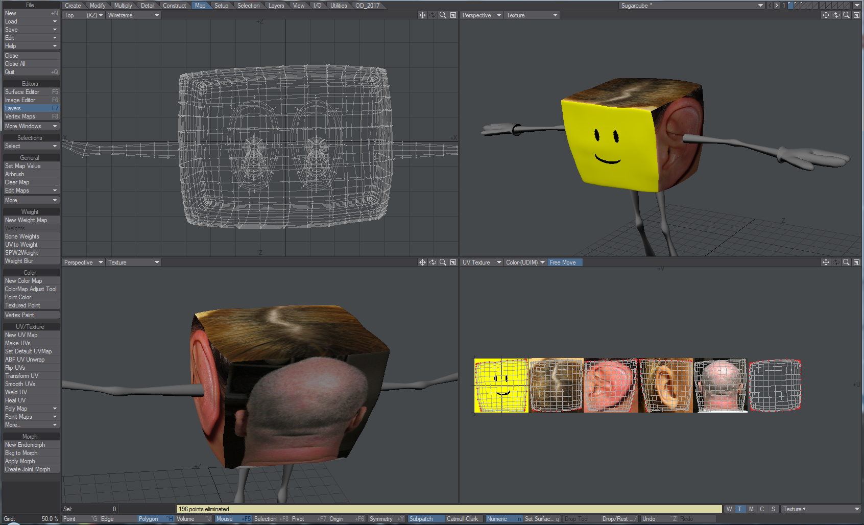
- One thing is still wrong with our texturing. Some of the tiles are mirrored - ears facing the wrong way, for example. Right now, our six faces for the cube are all separate objects so now is the right time to Flip UVs. Go into Map > UV/Texture and choose Flip UVs. Flip UVs will present you with a choice of flipping in the U, V, or both. The two directions in a UV map are similar to Left-Right and Up-Down respectively. Normally, flipping in U is what you need.
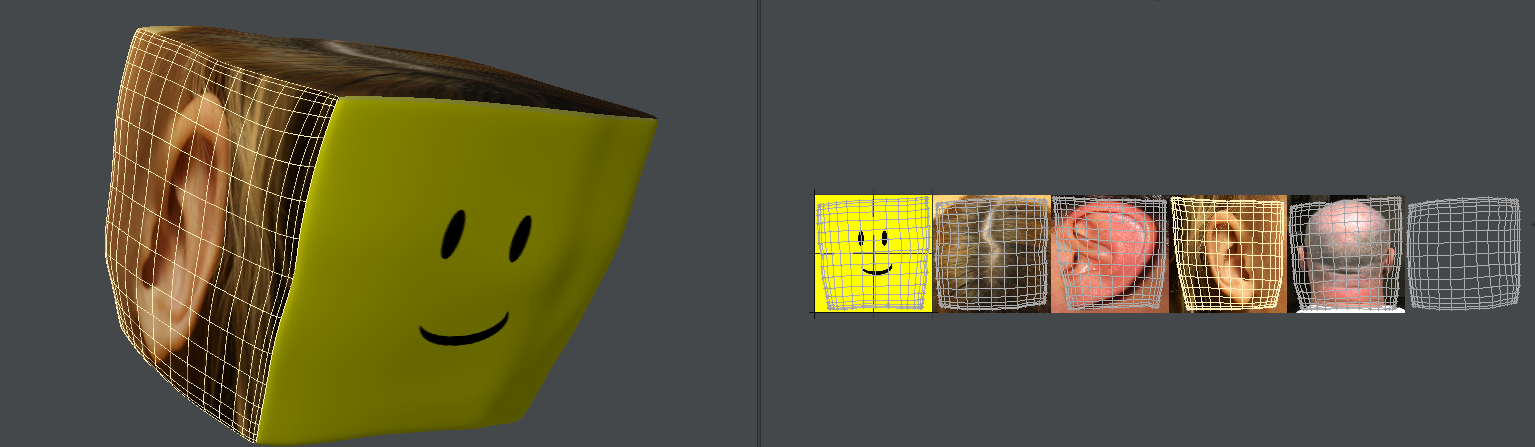
To see the image map overlaid on the UVs, select it from the dropdown at the top of the UV viewport - Once the UVs are the right way around and the image map fits correctly you can merge points (M) for the cube and unhide (\) the additional elements before saving.