Subpatch Modeling - Two
The goal of a modeler or any artist is to be able to create anything he can see or imagine. In part one, we went over some of the basic terms and theory concepts. Now we are going to learn how Subdivision Surfaces work from a very practical level. There are certain things I think are important to know about how SDS acts on a polygon mesh that will help us to predictably create any shape we want.
Subpatch Characteristics
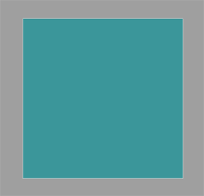
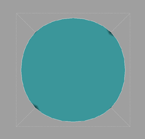
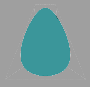
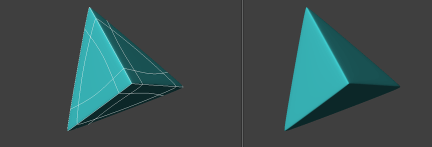
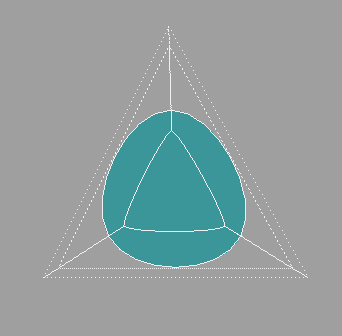
Subpatch characteristics are pretty intuitive to understand at first glance. You take a square polygon, hit TAB and it becomes a near circle. Pull the control points around and you can turn it into an egg shape etc. Basically it is approximating your base shape with curves.
Movement
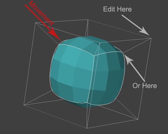
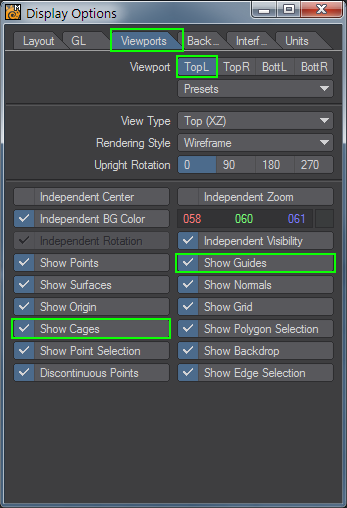
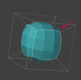
But as soon as we get past the simplicity of a square, cube or a ball we have to understand more than this. One very important characteristic of SDS is movement. Movement of vertices and edges from their original location to that of the subdivision surface. The most common understanding and use of this is to edit either the original vertex or the new one on the subdivision surface. In fact, it is often that the cages are turned off and the subdivision surface alone is edited. This gives you a better visual feedback on the shape. You can access this display option in the display options panel, "d" on the keyboard.
Now let's look into this a little further. In this first example we are going to explore the movement of vertices and edges on a flat rectangle that is subpatched. This is very simple but the purpose is to introduce a concept we will build on and use in other ways.
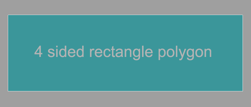
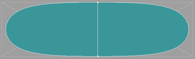
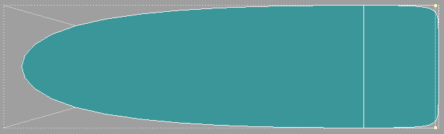
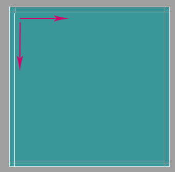
OK, we start with one four-sided rectangle polygon.
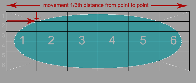
And when we subpatch it, notice that the vertex moves just about exactly 1/6th of the total distance from point to point on the X and on the Y. This does not mean much at this point. It is just giving us a formula to compare. The curve is just one continuous ellipse. It has no beginning or end.
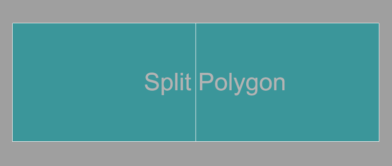
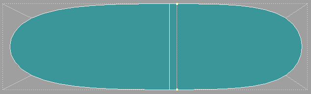
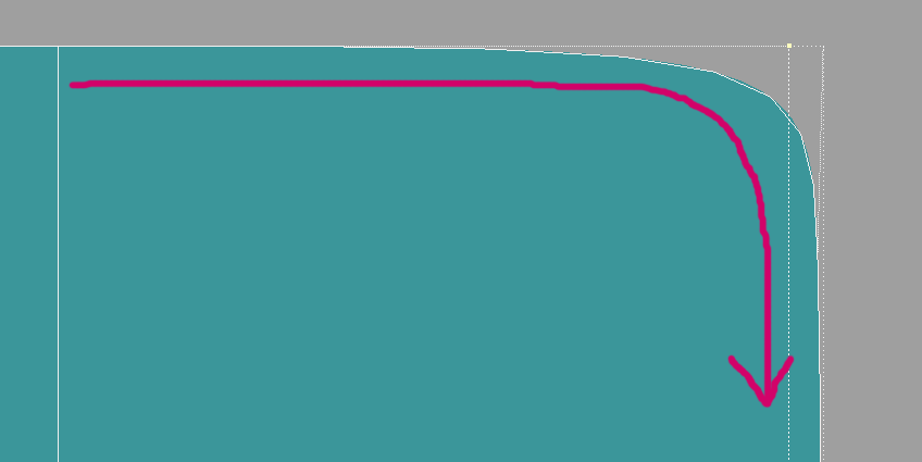
And so we now start to add geometry. We split it once down the middle.
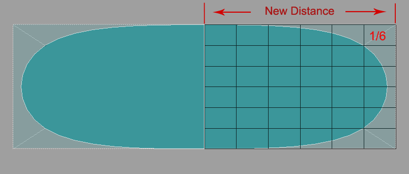
And when we subpatch and we get a new distance and the vertex moves 1/6th of this distance. So here is the first point we notice that the curve has a start point. It is now two U shapes that start from the middle. But more importantly we make note of the fact that the curve is being plotted from this new point and that the vertex moves the same percentage of distance from point to point. And that it is always calculating from all points it is connected to. In this case we are only in two dimensions so it is calculating a curve on the X and Y.
OK, So now we start to add more geometry.
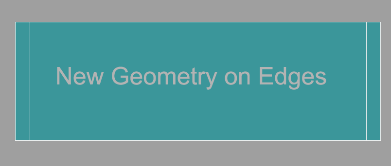
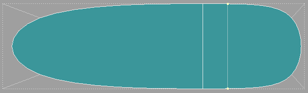
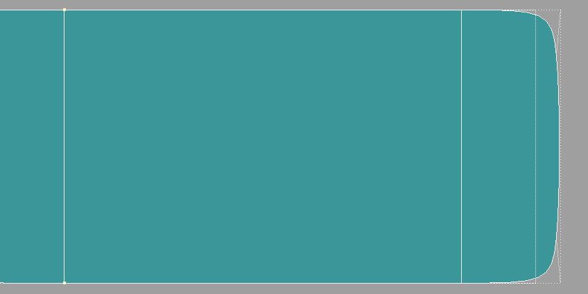
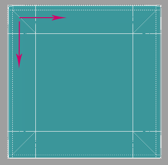
We start out with the rectangle again. This time we have added edges at each end.
And when we subpatch it the vertices, now also represented by edges, move toward each other or actually toward the center 1/6th of the total distance to the next point. In the first example where we split the polygon, notice it did not move since it was in the middle. But now that we put edges on the sides they do move toward the middle. The further they are from the nearest vertex the more they will move. And the reverse is true.
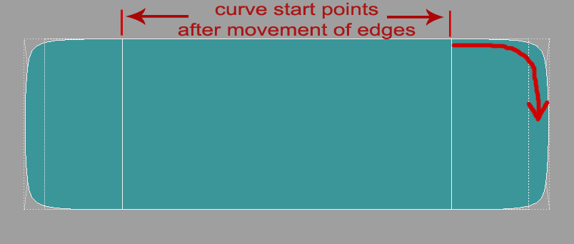
Our curve is tighter now and note that it starts from the position of the inner edges we have added. This is important. The curve will always start from where the vertex moves to.
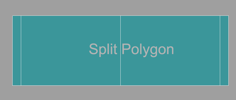
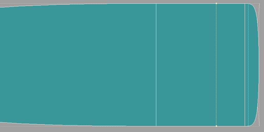
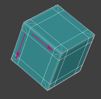
So now we will split the polygon down the middle.
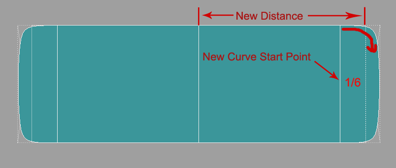
And notice that the outside edges do not move as far because we have shortened the distance to the nearest vertex. It is still moving 1/6th the distance but the distance is now shorter resulting in a tighter curve even though we have not adjusted the outer edge at all. Remember that the curve always starts from where the vertex moves to.
So up to this point we are talking about the distance between two points on a line.
Sliding Scale
But when we put a line in the middle as an extra control point, if it is at the direct center of that line, it has no movement. As you travel to the edge the gap gets wider. So it is not a constant percentage. It is on a sliding scale. Approximately 16.9% (1/6th) at the edge to 0% at the center point of the two edge points on that line.
Knowing this one bit of information will save you lots of head scratching and frustration as you move a line in on another line to get a tighter edge or give something any kind of sharper detail. You will wind up with edges so close together you can't edit them easily.
The solution is to add a line behind it and move it in so that it closes up the gap and tightens the curve.
So creating predictable shapes in subpatch is really a matter of restricting and controlling movement of vertices on the subdivision surface.
Poly Flow
The way we control or restrict the movement of vertices on the subdivision surface to get the shapes we want is through poly flow. There are two basic types of poly flow - hard and soft. As mentioned before, Grid Mesh and Edge Loops.
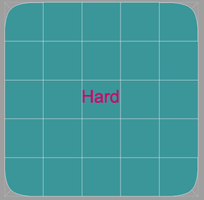
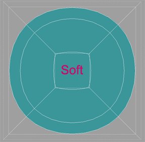
A grid is very good at holding a shape whereas edge loops give in and create curves.
Two kinds of movement
And with this then we can observe that there are two kinds of vertex movement along the subdivision surface.
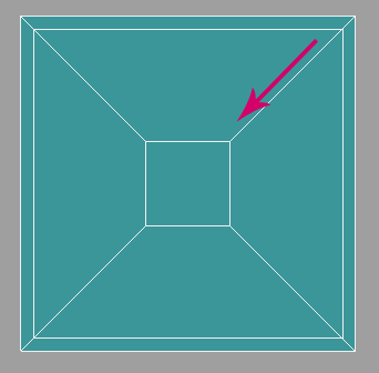
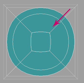
1. Along a vector.
2. Along a line.
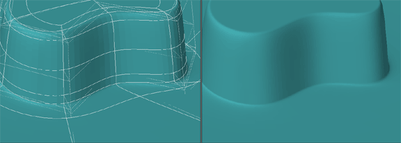
It is restricting vertex movement to the line that creates and angular shape or a sharp edge.
And allowing movement along the vector that creates a curve.
Strong and Weak Joints
And so we can further extrapolate that there are two kinds of joints:
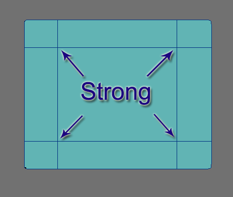
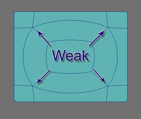
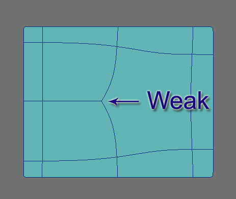
Strong and Weak
As mentioned in part one, these weak joints (3 and 5 poly points) are difficult to edit with predictable result. And now you can get an idea of why, since they move on the vector abnormally and allow for a curvature or bump that is an anomaly to the surface we are trying to create. 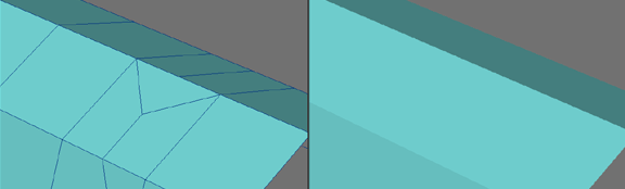
Poly Flow Examples
The Letter A
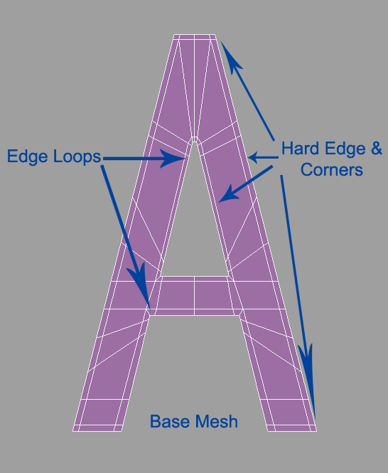
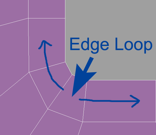
Using edge loops for the inside hole and legs allows for very clean geometry. All that is needed is to put some edges close to the corners and then edges on the outside of these to keep them from moving as much and you have a nice tight curve.
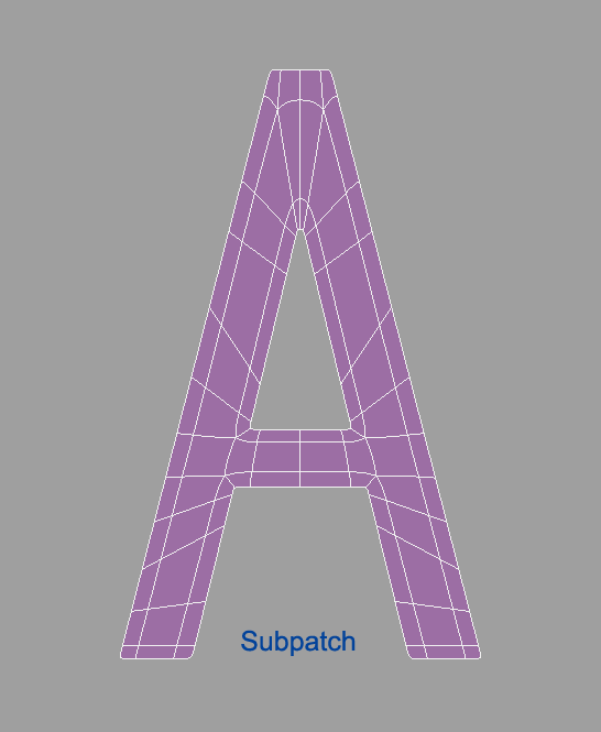
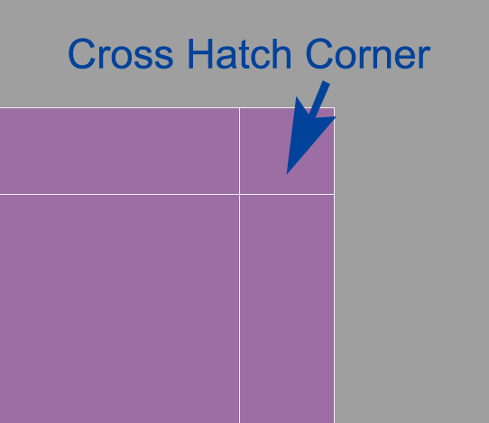
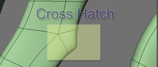
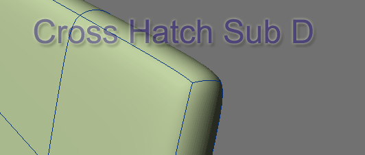
The outside corners can use simple cross hatch grid lines for a tight curved edge. Notice that there is little difference between the base mesh and the subpatch version. This is a clean, economical, controlled mesh.
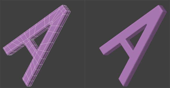
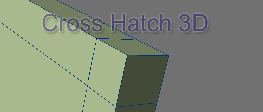
And it extrudes beautifully.
Now there is a very good reason not to use the cross hatch pattern on the inside tight corners. Also as a general rule, never connect two lines to one point on an edge unless it is an outside sharp corner like the top and bottoms of the letter A example.
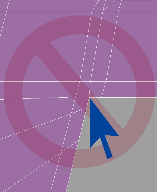
This configuration leaves a 5-point poly right on the corner when you extrude and it will never look quite right not to mention be hard to edit.
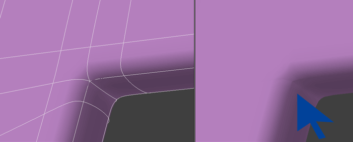
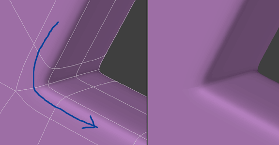
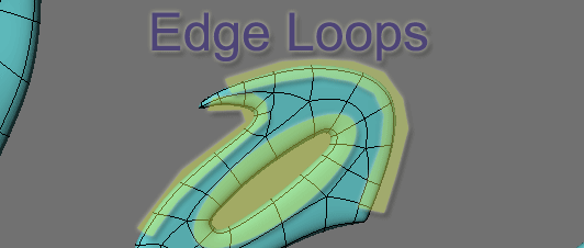
Inside tight corners and all curve edges should be an edge loop.
So in review we have used these two configurations:
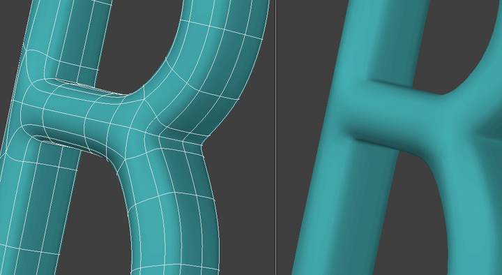
The Letter B
We will use them again in the letter B:
![]()
![]()
With the addition of the wide sweeping edge loops that make up the curves of the B.
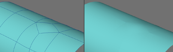
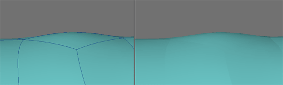
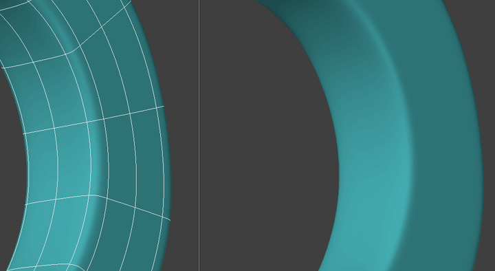
The center of the B poses a poly flow problem that we can get away with since it only has to be flat. If we needed to curve this, the weak joints would pose a problem we would have to solve to get a smooth arch.
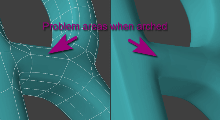
To solve it we have to add more geometry to smooth out the flow (with strong 4 poly joints) and we can have a much smoother arch on the surface:
And again this illustrates that the more complex the object, the more challenging it is to keep a clean poly flow. It also illustrates that you should model for what the job requires. You can get away with a lot on a flat surface and it will save time and polygons. But if it is to be curved you need to add more geometry to redirect the flow so as to eliminate as many weak joints as you can or place them where they are not a problem.
A Custom Font
Some samples from a font I created for a logo. You can see the various configurations that are all combinations of the edge loop and the cross hatch to create a transition of flowing curves into sharp points which are just various uses of the cross hatch pattern. Again here the logo only needs to be flat so I can get away with murder on the flat face and concentrate on my edges, but still doing my best to follow a logical flow and sticking to quads as much as possible.
![]()
![]()
Closeups:
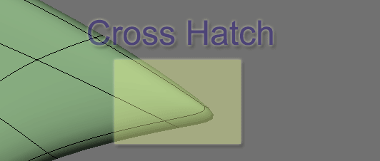
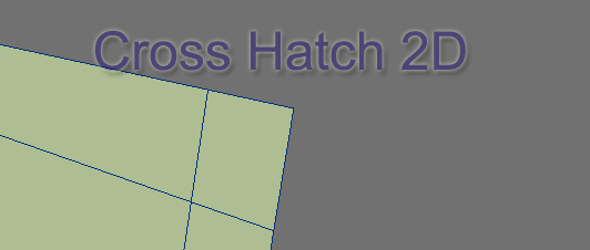
The Letters A and B and this logo example were created on a 2D plane and then extruded with the Extrude Tool. So you have two basic configurations.
The Cross Hatch:
The Edge Loop
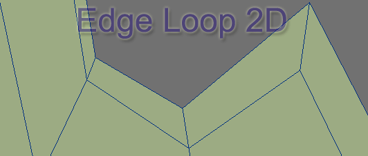
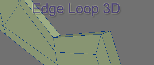
Working with these two configurations you can pretty much do anything.
Combined Polyflow
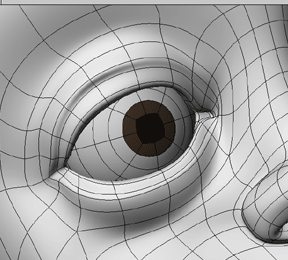
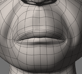
The other most common use of hard and soft poly flow is the placement of edge loops within the mesh. The mesh defines the shape and the edge loops create detail.
You would most often see this used to create eye sockets in a character head or the area around the mouth but basically any smooth shape or contour is delineated by the use of edge loops.
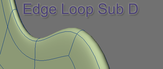
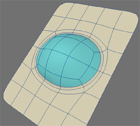
Creating hard edges in a loop
A series of concentric lines in an edge loop give you the ability to both a) hold the curve shape with the edge loop and b) allow for tight edges using lines with strong 4 poly joints, which are in essence grid lines. So both strong and soft poly flow working together to define the shape.
As I pointed out in the beginning, in general, subpatch modeling is a matter of laying out grid mesh and edge loops in such a way as to create the shapes we want. Working with objects that have a more intricate contour is more complex in a sense and pose different challenges in "connecting the dots", but the basics we have covered so far apply. From here it is just a matter of exploring their usage.