Import/Export
You may load foreign object and scene formats supported by LightWave directly into Layout or Modeler. To load an object in a foreign format into LightWave, you only need to use the normal Load Object menu entry. Complete explanations are found in the Interchange chapter of this manual starting page PDF_LINK. However, only Modeler can be used to save an object using a foreign object format. To do this in Modeler, choose File > Export and select one of the Export options.
Imported Object Formats
| Format | Supports |
|---|---|
| OBJ | M, SA, T, UV |
| DXF | M, SA |
| 3DS | M, SA, SSP, T, UV |
| DAE | M, SA, T, UV |
| FBX | M, SA, T, UV, Mrf |
| STL | M |
| PLY | M |
- M = Geometry mesh
- Mrf = Morph
- SA = Surface assignments (LW default properties)
- SSP = Standard surface properties (color, glossy, etc.)
- T = Texture maps (non-procedural)
- UV = UV texture information
When appropriate, an options dialog may appear when you load or save a foreign object format file. Some trial and error may be needed to get acceptable results. OBJ settings are presented in the Options window, available when tapping o in Layout or Modeler.
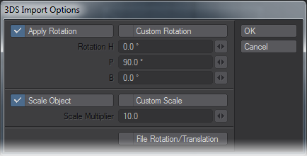
3DS import option dialog
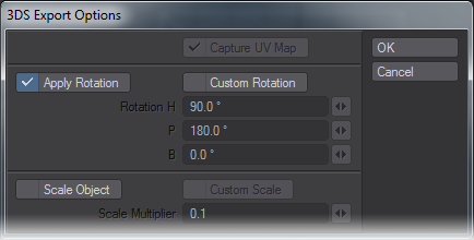
3DS Export option dialog
Image and Animation Types
You can load and save various image and animation formats. What is available to you depends on the platform you are using, as well as the plug-ins you have active. Please check the NewTek Web site (www.newtek.com) for additional plug-ins as they become available.
The Flexible Format, TIFF LogLuv, and Radiance image formats contain high dynamic range data (discussed below). In addition, they store the data with floating-point accuracy instead of using integers.
The filename extension for Radiance images is .HDR. If you have any of these images using the .PIC extension, you should rename them.
Supported image formats include but are not limited to: PSD, Alias, BMP, Cineon FP, DPX, Flexible Image Format, IFF, JPEG, PCX, PICT, PNG, Radiance, RLA, RPF, SGI, Sun, TIFF, Targa, VBP, and YUV image formats.
Supported animation formats: AVI (any installed codec), QuickTime, QuickTime Stereo, Flexible Image Format, Storyboard, 4X Storyboard, Film Expand.
Supported Web 3D: QuickTimeVR, VRML and Shockwave for export.
Images and Memory
Mipmapping is a process where a series of images with progressively lower resolutions are created from a base (full-resolution) image. Each pre-processed image is a power of two smaller than the previous level. As textures move farther away from the camera, they obviously must be scaled down. However, because the mipmaps are pre-processed and loaded into memory, they can be used immediately for textures instead of continually shrinking down the base image; this saves rendering time, but requires more memory. Eight-bit grayscale and eight-bit index-color images remain in eight-bit form internally. For color images, their mipmaps, however, are 24-bit since they must include colors in between color palette entries. Floating-point images use 96 bits per pixel and have 96-bit mipmaps.
Here are some examples dealing with a 512 x 512 image in various formats, and how much memory is used for the base image and the first couple mipmaps:
- 512 x 512 eight-bit grayscale image:
- Base image 262,144 bytes (512 x 512 x 1)
- First mipmap 65,536 bytes (256 x 256 x 1)
- Second mipmap 16,384 bytes (128 x 128 x 1)
- Total 344,064 bytes
- 512 x 512 eight-bit color-mapped image:
- Base image 262,144 bytes (512 x 512 x 1)
- First mipmap 196,608 bytes (256 x 256 x 3)
- Second mipmap 49,152 bytes (128 x 128 x 3)
- Total 507,904 bytes
- 512 x 512 24-bit image:
- Base image 786,432 bytes (512 x 512 x 3)
- First mipmap 196,608 bytes (256 x 256 x 3)
- Second mipmap 49,152 bytes (128 x 128 x 3)
- Total 1,032,192 bytes
- 512 x 512 floating-point image
- Base image 3,145,728 bytes (512 x 512 x 12)
- First mipmap 786,432 bytes (256 x 256 x 12)
- Second mipmap 196,608 bytes (128 x 128 x 12)
- Total 4,128,768 bytes
High Dynamic Range Images (HDRI)
In computer graphics, color is displayed as a triplet value: red, green and blue. These values typically range from 0 to 255. Those 256 steps of color represent eight bits and together all three channels make up a 24-bit image. This means the maximum amount of color or luminance variation an image is allowed is merely 256 steps.
In the real world, the human eye can perceive a much higher range of brightness and color values. Film can also react to a much wider range. Video cameras, however, are limited to a fixed range that fits closely to the same 256-step limit.
When exposed to high dynamic range visuals, such as a sunset or a desert landscape, the lens of a camera will produce some level of artifacting. Some of those artifacts can be seen as blooming areas of brightness, color bleed, luminance spill, lens streaking, and many other visual cues that tell the viewer there is a very bright light source in the scene.
These very bright surfaces can also contribute to the overall lighting of a scene. For example, sunlight streaming into a room will bounce off the floor and add a subtle illumination to the walls and ceiling that would otherwise be left dark ( this bouncing of light is known as radiosity). All of these effects can be seen in images captured by devices that do not support high dynamic ranges.
Because computer graphics applications were designed to output to devices that would not understand pixel values above RGB 255, 255, 255, most applications do not provide for any value to exceed these limits. LightWave, however, calculates all internal data without limits and with IEEE floating-point accuracy. This means that when LightWave points a light at a surface, while the final rendered pixel may reach only RGB 255, 255, 255 for pure white, internally that pixel may have reached ten times that amount. This may not seem significant at first glance - white is white after all - but, if we look at how LightWave utilizes that data, it becomes very exciting.
Import/Export
LightWave can utilise high dynamic range detail, as it is generated internally (e.g., in the case of a very bright light) or from data in image files. This can be imagery generated from a series of photographs taken at various exposures and composited (see Recovering High Dynamic Range Radiance Maps from Photographs by Paul E. Debevec and Jitendra Malik at ) or data rendered in LightWave saved in one of the high dynamic range formats.
Once these images are imported into the system, they can be used just like any other image in LightWave 3D (e.g., as a texture, background, etc.). During the rendering process LightWave will respect the extra data in the image to assist in secondary lighting and other calculations.
Imagine using a high dynamic range image as an environment wrap (e.g., using the Image World environment plug-in.), which also illuminates the scene. With the appropriate imagery you can illuminate a scene without any lights and the results will match the look and feel of the original photograph.
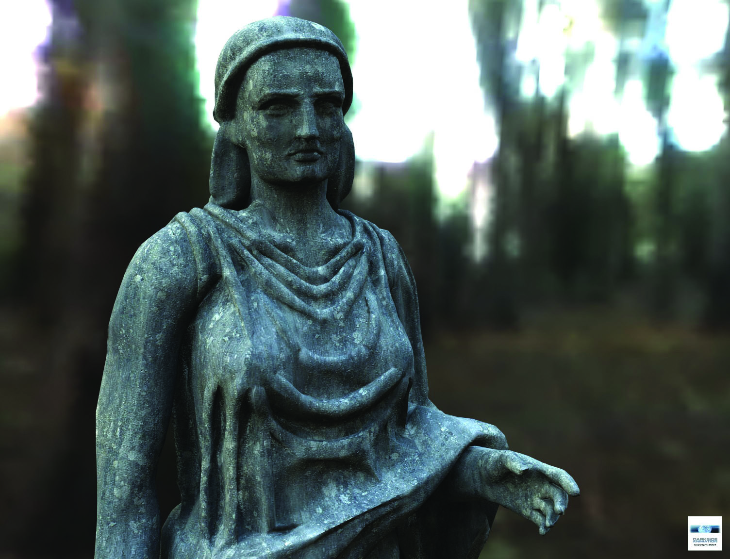
Image by Darkside Animation
Once LightWave finishes rendering, you can export images with the same high dynamic range data. This lets you bring that data back into LightWave or into compositing applications that support such data. Using this extra data in the compositing process is very important as it can more accurately represent imagery as it would look if it were recorded directly to film. For example, compositing applications could use the extra dynamic range data to calculate the amount of diffuse bloom or color bleed from one pixel to the next.
Internal Compositing
Another area where high dynamic range imagery is supported is in LightWave’s own internal compositing through pixel and image filters. Any filter can be designed to take advantage of the high dynamic range data with floating-point accuracy. This way, high dynamic range data can be leveraged in the post-process phase with included filters and by third party additions.
Preview Compression Codec
The NTCodec.dll adds LightWave’s preview compression scheme into the Windows AVI codec. You just need to install it if you want to play/load compressed preview anims into other Windows applications/players. See the README.TXT file located in the NTCODEC directory for installation instructions.
The Hub
The Hub is essentially a message board that LightWave modules use to synchronize information. It contains entries like synced object filenames and configuration memory blocks. When the same object is loaded into both Layout and Modeler, changes made to the object are automatically synchronized. If the object appears in Layout, but not Modeler, you can quickly load it into Modeler by selecting it from the object pop-up menu - initially, the name will be ghosted.
The Hub runs automatically when you run LightWave. Basically, it is a background process and you shouldn’t need to directly interact with it. However, you can bring up its interface by clicking its icon (when running).
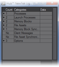
If you expand the Launch Processes menu, you should see applications that the HUB is aware of (e.g., Layout, Modeler). You can launch the application by double-clicking it. If you single-click (to select it) and then press the l key, you will also launch the application. If you press the Del key instead, you will delete the application from the launch list. (This has no effect on the program files on your hard drive.)
Open Open Hub window Close Close Hub window Launch Launch applications that the Hub knows about Properties Set options to quit the Hub after you exit LightWave Exit Close the Hub program
Properties
You can set the Automatic Shutdown to various time intervals, after which the Hub will shutdown when there is no activity. Note that even when Layout and Modeler are idle, there is still some minimal communication activity which will keep the Hub from shutting down.
When Layout or Modeler are running, you can set LightWave to auto-save objects and scenes in your Preferences dialog. On the General tab go down the near the bottom where you will see two dropdown menus, one for auto-saving Objects, the other for Scenes. In Modeler, you can just choose to auto-save Objects in the General Options panel.
Command IPC
We have implemented an interprocess communications system, CommandIPC, into Layout and Modeler. When LightWave is started without Hub support (the -0 command line option), Layout and Modeler all notify each other when a mesh file has been saved to disc, and the applications that have that file open and have not applied modifications during the session will update from the new version on disc. For example, if both Layout and Modeler have “bob.lwo” open, Modeler has some edits applied to it, and Layout saves it transformed, Modeler will not automatically update from the disc.
If subsequently the object is saved out from Modeler, that will overwrite the changes made by Layout, and Layout will update from the save if no further changes were applied in Layout during the interim. LightWave CORE users should note that the IPC system is only active in the Windows and Mac builds, since LightWave HC code is not built for Linux.
The ‘isolate’ flag (‘-i’) will completely disable all IPC mechanisms (Hub and CommandIPC), leaving the application isolated from all other product actions.
Optimizing RAM Usage
If your computer is accessing virtual memory frequently during rendering, you may find a substantial increase in performance by installing more RAM on your machine or reducing the amount of RAM LightWave needs to store the render information.
One of the best ways to minimise the need for RAM is to reduce the color of the images used for texture mapping effects. Except for those used as a Surface Color, Texture Maps usually need to be only 256-level greyscale images.
Other ways to reduce RAM usage are to render your animation in multiple passes or decrease Segment Memory Limit on Layout’s Render Globals Panel.