Mesh - Edges

When rendering edges that are not even a pixel wide, make sure to increase camera samples since the camera could "miss" edges if only one sample is used.
 Edge/Outline/Line/Point Rendering
All edge types work on instances. Nodal shaders can be used to adjust the taper, color and opacity of the edges. Lines and outlines can be tapered. Using a negative value for the thickness of any edge, line or outline causes them to be rendered in perspective. The negative thickness is used as a radius in meters. This shows in both rendering and interactive VPR.
Edges are a particular means of wireframe rendering. Unlike surface-based inking with high-contrast incidence-angle gradients (think of the computer-generated Galactus in the 1990’s SILVER SURFER cartoon), Edges can look as stable as any wireframe render. For models made of subpatches, this means that higher Render Subpatch Levels will deliver smoother ink lines, and lower Render SubPatch Levels will provide chunkier ink lines.
To render all possible Edges in a scene, make sure that Render Lines is enabled in Render Properties - Render.
To set the Edges for an individual object, select that Object and open up its Properties panel. Go to the Edges tab to see the Edge settings. To turn off Particle/Line Thickness rendering for just that object, set the value of Particle/Line Thickness to 0.0. The remaining Edge types use on/off checkboxes, and they will be turned off by default. These can be turned on individually by clicking on their names to activate their checkboxes.
- Particle/Line Thickness - this value handles the thickness of one-point and two-point polygons. One-point polygons will render as Particles, and two-point polygons will render as Lines. With negative values, one-point polygons become raytraceable spheres, and two-point polygons become raytraceable tubes. Unlike the other Edges, the surfacing for Particles and Lines are controlled by the Surface Editor. For example, if you would like your one-point polygons to render with a blue color, go to the Surface Editor and set the Surface assigned to those one-point polygons to the color blue.
Edge Types
Silhouette Edges - these render along the edge shared by two polygons when the normal of one of those polygons faces the camera, and the normal of the other polygon faces away from the camera. The edges that qualify as Silhouette Edges will change with the angle of the model to the camera. This means that rotating the model, deforming the model or moving the camera will change the Silhouette Edges on each frame. An edge must be shared by two polygons to qualify as a Silhouette Edge - Silhouette Edges will never appear on a mesh that consists of a single polygon.
Silhouette Edges follow a similar rule to that followed in life drawing classes: a line represents the point where the surface of the subject matter turns away from the viewer.
Unshared Edges - these appear on edges not shared by any other polygon. Unshared Edges, when checked, will always appear on a model that consists of a single polygon. For non-subpatch models, selecting an area of geometry and then applying a “Cut and Paste” operation will create an Unshared Edge at the border of the selection in your object. You might use this trick to get Edges to help you describe the panels in a spaceship, for example.
Any overlapping points of a subpatch model will get “merged” into a shared edge in Layout for Render SubPatch levels higher than 0, so the “Cut and Paste” trick will only help you sharpen edges in your model - it will not give you an “Unshared Edge” in Layout. If you want the “Cut and Paste” trick to work on subpatch models, create an endomorph that separates the overlapping points. Layout will back off when it sees the endomorph, and it will not merge those points.
- Sharp Creases - might also be called “UnSmoothed Edges”. Whether or not a given edge qualifies as a Sharp Crease depends on the Smoothing Angle of the surface to which that polygonal edge belongs. Lowering the Smoothing Angle of a surface will increase the number of Sharp Creases traced; increasing the Smoothing Angle will decrease the number of Sharp Crease edges. If the “Smoothing” option is left unchecked in the Surface Editor, most (if not all) of the polygon edges in your model will qualify as Sharp Creases. These edges could be good for sharp-edged machinery, buildings and rocky terrains. If the object is deforming (for example, an animated ocean surfaced with a low Smoothing Angle), the smoothed/unsmoothed property of the edges can change from frame to frame, and the Sharp Creases will change with them.
- Surface Borders - this type of Edge will appear at the edge shared by two polygons when those polygons have different surface names. The polygons can have the same texture parameters, but Surface Borders will not care. If the surface names differ, then the polygons will have an ink line render along their shared edge (unless the artist leaves Surface Borders unchecked).
- Patch Borders - shows the borders of subpatches in VPR and F9 renders instead of the triangular polygons subpatches are made from.
- Intersection Edges - shows where two objects interpenetrate without requiring a boolean operation. They work equally well with subpatch and polygonal objects; still or with animation.
- Other Edges - any polygonal edge that does not qualify as a Silhouette Edge, Unshared Edge, Sharp Crease or Surface Border will fall into this group. Turn this on along with all of the other Edges for an old-fashioned Wireframe Render.
- Surface Shaded - Allows Surface Editor shading of edges. See Mesh Element Switch.
Positive values will render in a fixed screen size defined in pixels. For example, a 1.0 pixel thickness will always draw an Edge of 1.0 pixels no matter how close or how far away the object is to the camera.
Negative values will render raytraceable spheres and tubes and define the thickness of the Edges in meters (3D space) instead of pixels (screen space). A value of -0.01 will always draw an Edge of 1cm (0.01 meters) in 3d space that will shrink/increase as the object changes its distance from the camera.
Using the Node Editor for Particles, Lines and Edges enables more control. These properties are offered for most Edge types:
- Taper - the thickness of the particle, line or Edge. Suggestions:
- Use the Alpha of a Turbulence texture to create a wobbly line.
- Use an Incidence Angle gradient on Unshared Edges, Sharp Creases, or Surface Borders to taper those non-Silhouette Edge types as the surface turns away from the camera.
- Use a Weight Map to control the taper of Silhouette Edges. Use low values to taper the lines as they approach “corners” of the model. On a character’s face, those “corners” could be the tip of the nose, the bottom of the chin or the edge of the lip. These points would be where the artist’s brush or pencil lifted up from the paper at the end of a brush stroke or pencil stroke, so the lines should taper there.
- Use a Distance to Camera gradient to shrink pixel-sized ink lines as the subject matter gets farther away from the camera.
- Color - the color of the Edge. Ideas:
- Use a Gradient that controls the color of the Edges, so that the most brightly lit areas have the lightest color and the most shadowed areas use the darkest color. This approach to inking was used in the 2003 animated feature, Wonderful Days (also known as Sky Blue).
- Use a Weight map to mask off different sections of a model, then use those weight values to drive a Color gradient so that each section of the mesh has a different-colored ink line.
- Opacity - the transparency of the Edge.
As mentioned above, Particle/Line surfacing properties are handled in the Surface Editor, so Color and Opacity are not available for “Lines.”
In the Edges tab, Edge Color offers a base color for Edges that can be overwritten by the Node Editor.
Edge Z Scale is a legacy property. We strongly recommend leaving it at its default value of 1.0.
Edge Functionality
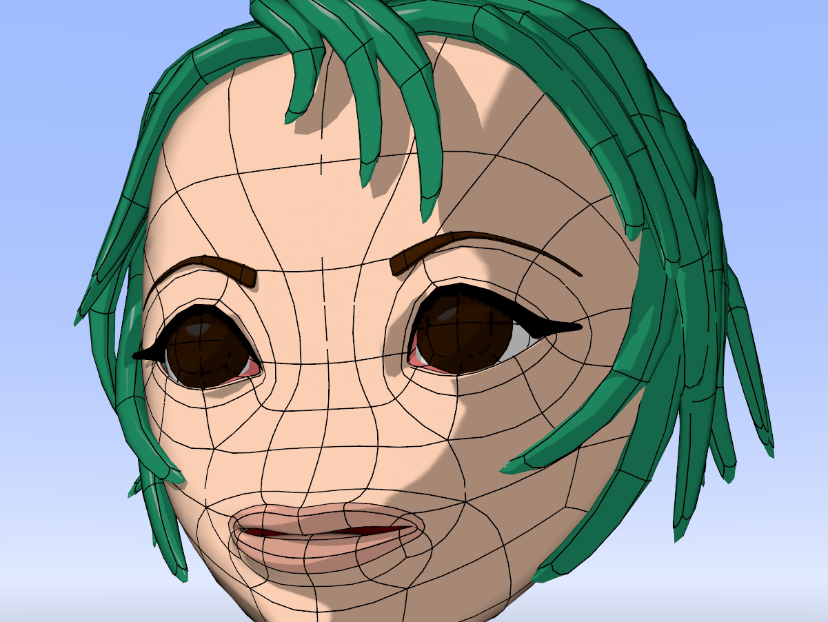
Patch Borders used to show the subpatch basis of this model
Example
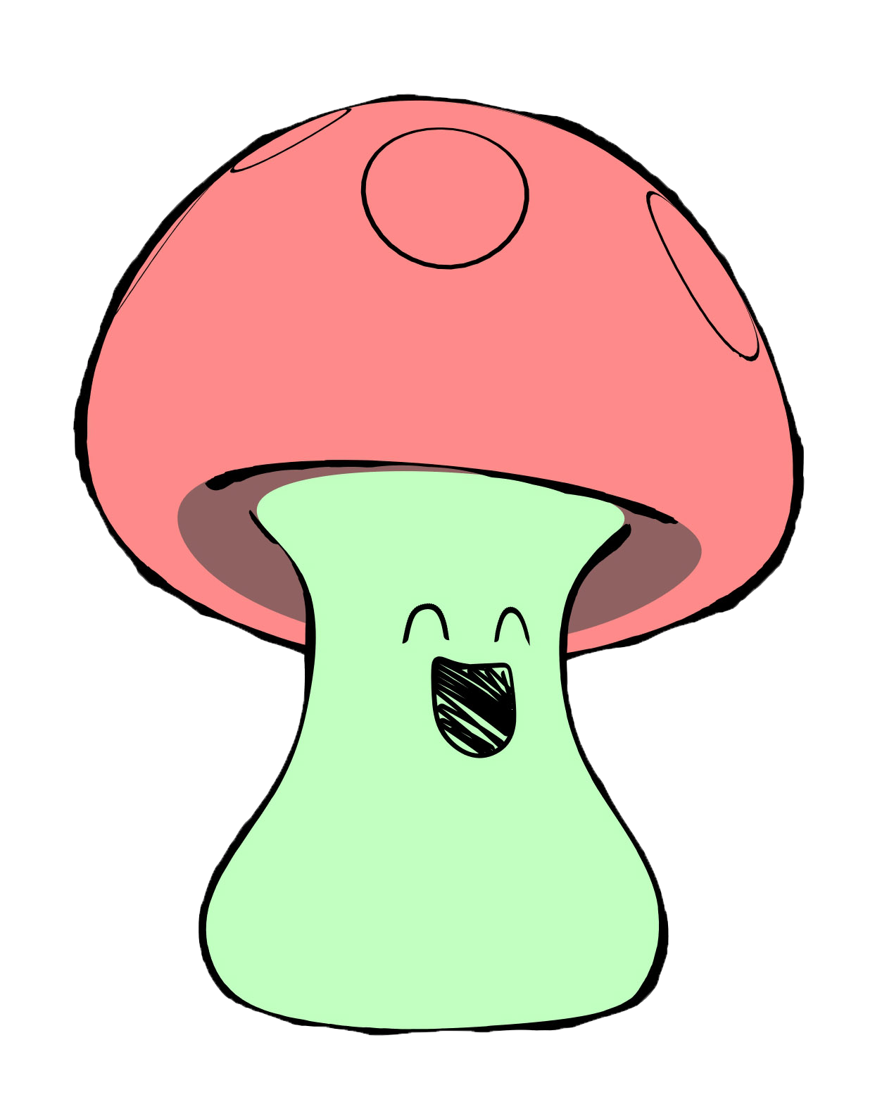
The cartoon mushroom rendered here makes use of intersection edges to produce the face and circle line work, avoiding the need to paint and map images to achieve the desired 2D look. To produce an illustration appearance to this character, no cel shading was used. The surface uses a diffuse of 0% and luminosity of 100%, with the surface colors being produced by a gradient controlled by a weight map set up for the bones in the character. The circles and the face geometry are two separate layers of geometry that intersect with the base character form. They share the same weight maps as the base layer and make use of the option to use the bones from the base layer. This enables them to deform along with any squash and stretch actions. The face is animated through a series of morph targets applied to the geometry producing the face edges. By utilizing intersection edges, any requirement to produce animated facial image maps that are carefully timed to match the performance are not needed. The performance is controlled by the animator. Silhouette edges are applied, and their taper value is animated through the node editor with a crumple procedural texture. This breaks up the thickness of the line work and creates a more organic appeal to the style.
Mushy character and explanation courtesy Kevin Phillips
Kawai_shroom.7z
Example - Shadowing Options with Edges
An example that shows use of the Mesh Element Switch and Ray Type Switch nodes to control shaded edge shadows