Vertex Paint
Overview
Vertex Paint is a Modeler plugin that lets you interactively “paint” a Vertex Color Map on objects and Weight Maps on Skelegons.
A Vertex Color Map is a LightWave feature that lets you assign colors to an object’s vertices (i.e., points). Vertex color maps are a basic LightWave feature so you can render their effect without using surface shader plugins. Although similar to Modeler’s Airbrush tool, Vertex Paint has its own independent interface for painting.
LightWave Skelegons let you define bones in Modeler. Weight Maps can provide additional deformation information. Vertex Paint provides a variety of features for you to set weights for Skelegons. You can see how the weight will deform the object in real-time while painting.
The Vertex Loader plugin can be used to load the bone information modified in Layout so that you can edit weights using Vertex Paint.
How to launch Vertex Paint
Vertex Paint consists of two plugins: Vertex Paint and Vertex Loader.
If you want to edit a Vertex Color Map or Weight Maps (for Skelegons):
First, load an object you want to edit into Modeler. Then, choose Map > Color > Vertex Paint. For Skelegon Weight Maps, your object must already have Skelegons. The Skelegon names set by certain tools, such as Skelegon Tree, are used for each Skelegon’s Weight Map name.
If you want to edit weight maps using Layout bones:
Use Vertex Loader to load objects with bones that were created from scratch in Layout, or bones that were converted from Skelegons, in order to edit the Weight Maps in Vertex Paint.
To use Vertex Loader, choose File > Import > Vertex Loader. First the Load Scene requester opens; select a scene file that has object(s) with bones. After you select a scene file, the dialog box shown below appears. There you select an object that you want to edit and click OK.
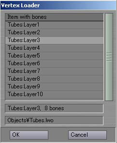
The selected object is automatically loaded into Modeler and displayed in Vertex Paint with its bones. If the object is already loaded, only the bones are loaded from the scene file. Weight maps set on the Bone Properties panel in Layout are used for each corresponding bone.
Before launching Vertex Loader, make sure Layout’s Content Directory setting matches Modeler’s.
If multiple skelegons share the same weight map name:
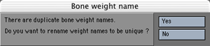
If a single weight map is shared by multiple Skelegons (or bones), Vertex Paint displays the dialog box below. Generally, one weight map should correspond to only one bone in Vertex Paint.If you click Yes, Vertex Paint automatically uniquely renames the map so there is no longer a duplicate. If you click No, Vertex Paint makes an exception and allows a “shared” weight map.
Saving the Data
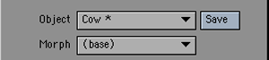
Changes made in Vertex Paint are not automatically updated in the Modeler object. To reflect the Vertex Paint changes, click the Save button or choose Save To Modeler from the Edit menu. (An asterisk (*) next to the object name means the object has additional information not yet updated.)
The following is what Vertex Paint updates:
- Vertex Color - (RGB VMap, RGBA VMap)
- Weight - (WGHT VMap)
- Morph - (MORF VMap, SPOT VMap)
- Bone name - (BONE, PART PTag)
- Bone Weight name - (BNWT PTag)
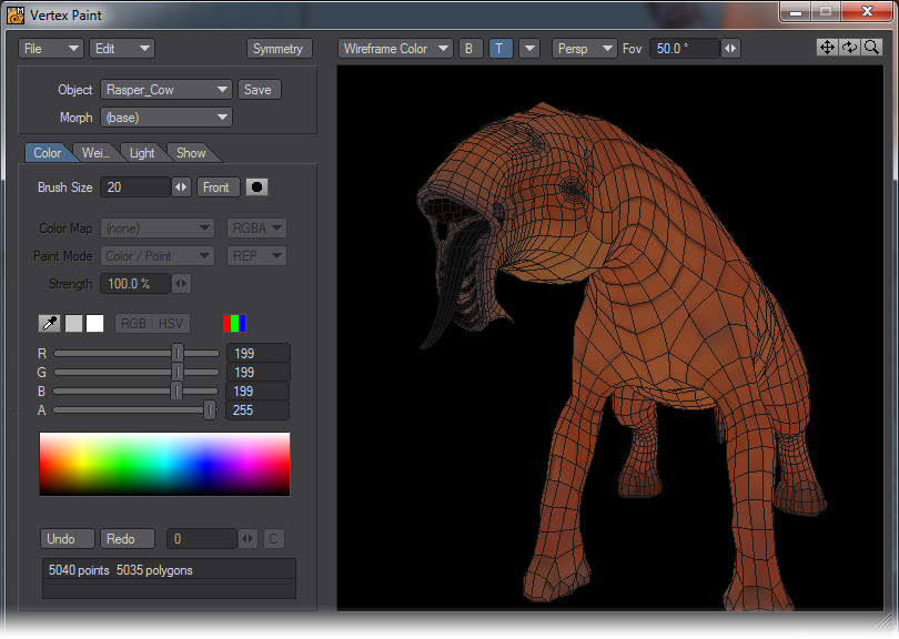
Vertex Paint: User Interface
Choose Map > Color > Vertex Paint to launch Vertex Paint. The interface appears below.

 Changing the size of the main panel
To change the size of the main panel, drag the mark at the bottom-right corner with LMB. The display will be jumbled while dragging, but once you release the mouse button, it will display properly.
Manipulating the 3D window
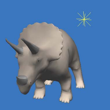
The large window on the right side of the panel is a 3D view where you can paint the vertex color of the loaded object or edit the weight value of bones. When you first run Vertex Paint, the 3D view displays the object you are going to edit. The 3D view is changed in much the same way the Perspective view is in Modeler.
 Rotating the view
There are two ways to rotate the 3D view. One is to drag your LMB on the rotate button at the upper right of the panel. The other is to drag your LMB while pressing Alt key. Both ways rotate object in the direction you drag.
 Moving the view
There are two ways to move the 3D view. One is to drag your LMB on the pan button at the upper right of the panel. The other is to drag your LMB while pressing Shift key. Both ways move object in the direction you drag.
 Scaling the view
There are two ways to rotate the 3D view. One is to drag your LMB on the zoom button at the upper right of the panel. The other is to drag your LMB while pressing Alt and Ctrl keys. Moving your mouse cursor to the right magnifies the object, and moving to the left reduces the object.
Perspective and Orthogonal view
Vertex Paint supports both the perspective projection and the orthogonal projection to display objects in 3D space. To display the object in perspective projection, select Persp from the 3D view info pop-up menu. To display the object in orthogonal projection, select Ortho from the 3D view info pop-up menu. You might find that you can paint vertices easier with the Ortho mode. Changing the camera zoom factor
You can change the camera’s zoom factor when you are in the Persp mode. Dragging the mini-slider next to Fov at the top of the panel left or right, zoom factor changes. Increasing the value, the camera lens will be a telephoto lens, and decreasing the value, it will be more wide-angle.
Changing the view
Click the down-arrow popup at the top of the panel to change the 3D view display.
- Front View - displays the object from the front side.
- Back View - displays the object from the back side.
- Right View - displays the object from the right side.
- Left View - displays the object from the left side.
- Top View - displays the object from the top side.
- Bottom View - displays the object from the bottom side.
- Fit Mode - displays the object at the center of the display.
- Fit Bone - displays the selected bone at the center of the display.
Switching the display mode
Vertex Paint can display objects using various display modes depending upon your needs. To change, use the pop-up menu at the upper left of the 3D view.
- Points - Displays the points that make up the object. The vertex color is set for the point color. Light source is not used.
- Wireframe - Displays the objects in wireframe. The vertex color is set for each vertex of the lines, if the color is different between the start and end point of the line, it displays a gradient color. Light source is not used.
- Front Face - Displays only polygons with normals facing the camera in wireframe. Light source is not used.
- Vertex Color - Displays the polygons in color, using the vertex color map currently selected. Light source is not used.
- Wireframe Color - Displays the polygons in color using the vertex color map currently selected, and also displays wireframe over it. Light source is not used.
- Lighting Shade - Displays the objects using the light source set on the Light menu. The object’s surface information is used for the polygons’ color attributes. No vertex color shown.
- Weight Value - Displays the weight value assigned to the currently selected bone in red gradient. If no bones exi st, it displays in grey.
- Weight Ratio - Displays the weight ratio of the vertices for the selected bone. Stronger color means more weight. Each bone has its own unique color. color. If no bones exist, the object is displayed in grey.
 B Button
Clicking the B button on, switches to the “Blending display mode”. This is a blending display using the vertex color alpha in the Vertex Color and the Wireframe Color modes. This also enables the translucent display of the texture, using its alpha plane.
 T Button
Clicking the T button on, switches to the “Texture display mode”. This is a texture mapping display visible in the Vertex Color, Wireframe Color and Lighting Shade mode.
 Rotating a Bone
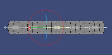
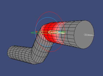
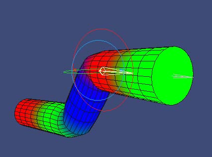
When the rotate button next to the bone VMap name on the Weight menu tab is showing, you can rotate the bones and see how the object deforms. Each ring means: Red=Heading (Y axis), Green=Pitch (X axis), and Blue=Bank (Z axis).
Clicking the button next to the bone VMap name cycles it through its settings (rotate, scale, move).
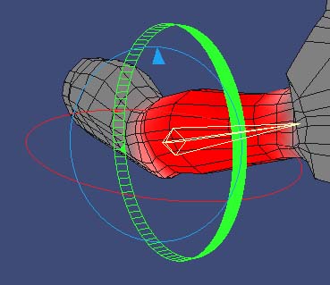
To rotate the bone, drag on the 3D window with LMB while pressing Ctrl key. The bone rotates as your mouse goes.
To rotate along only one axis, hold Ctrl and select the ring of the axis you want to rotate with LMB, then drag it. Selected ring is shown as a wide-band ring.
To reset the rotated bone at the default (Rest Position), with the Weight Tab selected, choose Reset the Bone from the Edit pop-up menu. To reset all the bones, choose Reset All Bones.
 Moving a Bone
When the move button next to the bone name on the Weight menu tab is showing, you can move the bones and see the deformation. A coordinate axis as shown below is displayed for the current bone. Each axis represents: Red=X axis, Green=Y axis, and Blue=Z axis.
Clicking the button next to the bone VMap name cycles it through its settings (rotate, scale, move).
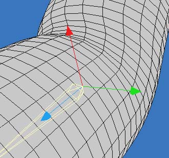
To move the bone, hold Ctrl and drag on the 3D window with LMB.
To move along only one axis, hold Ctrl and select the axis you want to move and then drag it. The selected axis is shown as a bold line.
 Scaling a Bone
When the zoom button next to the bone name on the Weight menu tab is showing, you can scale bones up or down. A coordinate axis as shown below is displayed for the current bone. Each axis represents: Red=X axis, Green=Y axis, and Blue=Z axis.
Clicking the button next to the bone VMap name cycles it through its settings (rotate, scale, move).
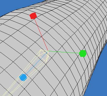
To scale the bone up/down, hold Ctrl and drag on the 3D window with LMB. Dragging your mouse up/right scales up the bone, and dragging your mouse to down/left scales down the bone.To scale along only one axis, hold Ctrl and select the axis you want to scale with LMB then drag it. The selected axis is shown as a bold line.
Changing the Mode
Vertex Paint has four working (editing) modes. You can change those modes by clicking on the menu tabs at the center-left of the window. Note that the Edit pop-up menu will show the different menus depending on what mode you are in.
- Color - Vertex color edit mode
- Weight - Bone weight edit mode
- Light - Light setting mode
- Show - Polygons Show/Hide setting mode
Displaying a Morph Target
If the object contains EndoMorph targets, you can choose the displayed target on the Morph pop-up menu.
Vertex Paint: Showing / Hiding Polygons - Selecting / Deselecting Polygons
Select / Deselect Polygons Using Your Mouse
When you are using the + Sel Mode, you can select polygons by dragging your LMB over them in the 3D view.
When you are using the - Sel Mode, you can deselect polygons by dragging your LMB over them in the 3D view. Dragging with your RMB deselects the polygon regardless of what selection mode you are in.
Hold the Ctrl and Shift keys as you drag your LMB to select/unselect using a bounding box. Hold the Ctrl and Shift keys as you drag your RMB to select/unselect using a lasso. You can toggle the Sel Mode by pressing the Space key.
Left: Bounding box selection. Right: Lasso selection
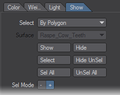
Show / Hide Polygons By Polygon
Vertex Paint can show/hide polygons either by polygon or by surface. Select By Polygon from the Select pop-up menu to manipulate by polygon. There are also some selection and hiding functions available in the Edit menu.
| Show | shows all polygons |
| Select | selects all polygons |
| Hide | hides selected polygons |
| Hide UnSel | hide unselected polygons |
| Sel All | selects shown polygons |
| UnSel All | unselects shown polygons |
Default Mouse Operations
The following table is a list of the mouse operations. You can customize the operation on the Preference panel (File > Preferences).
| Operation | Command | Action |
|---|---|---|
| LMB ALT-SHIFT | View Move | Move the view |
| LMB ALT | View Rotate | Rotate the view |
| LMB CTRL-ALT | View Zoom | Scale the view |
| LMB | View Tool Move | Move the view (using the icon) |
| LMB | View Tool Rotate | Rotate the view (using the icon) |
| LMB | View Tool Zoom | Scale the view (using the icon) |
| LMB | Color Paint | Paint the vertex color (in Color mode) |
| RMB | Color Radius | Show size of the color paint brush (in Color mode) |
| LMB CTRL-SHIFT | Color PickColor | Select color from the 3D view (in Color mode) |
| LMB | Color Palette | Select color from the color palette (in Color mode) |
| LMB | Weight Paint | Paint bone weight (in Weight mode) |
| LMB CTRL | Bone Navigate | Rotate/Move/Scale the bone |
| LMB SHIFT | Bone Select | Select the bone |
| RMB | Weight Radius | Show size of the weight paint brush (in Weight mode) |
| LMB CTRL-SHIFT | Weight Rectangle Select | Rectangle selection of the point (in Weight / Info mode) |
| RMB CTRL-SHIFT | Weight Lasso Select | Lasso selection of the point (in Weight / Info mode) |
| LMB | Light Move | Move the light source (in Light mode) |
| LMB | Show Select | Select the polygon (in Show mode) |
| RMB | Show UnSel | Deselect the polygon (in Show mode) |
| LMB CTRL-SHIFT | Show Rect Select | Rectangle selection of the polygon (in Show mode) |
| RMB CTRL-SHIFT | Show Lasso Select | Lasso selection of the polygon (in Show mode) |
Keyboard Shortcuts
| Key | Action |
|---|---|
| A | Display object at the center of the window |
| Shift-A | Display current bone at the center of the window |
| , | Zoom out |
| . | Zoom in |
| Shift-F | Display object in Front view |
| Shift-T | Display object in Top view |
| Shift-S | Display object in Right side view |
| F1 | Points Display mode |
| F2 | Wireframe Display mode |
| F3 | Front Face Display mode |
| F4 | Vertex Color Display mode |
| F5 | Wireframe Color Display mode |
| F6 | Lighting Shade Display mode |
| F7 | Weight Value Display mode |
| F8 | Weight Ratio Display mode |
| U | Undo |
| Down | Select next bone |
| Up | Select previous bone |
| C | Copy current bone weight |
| V | Paste to current bone weight |
| Shift-V | Paste to current bone weight symmetrically in X axis |
| X | Clear current bone weight |
| + | Scale up current bone weight |
| - | Scale down current bone weight |
| R | Reset current bone rotation |
| Shift-R | Reset all bone rotation |
| * | Step forward |
| / | Step backward |
| T | Bone move mode |
| Y | Bone rotation mode |
| H | Bone scale mode |
| - | Hide current polygons |
| = | Hide unselected polygons |
| | | Invert Show/Hide polygons |
| SPACE | Switch polygon select/deselect mode |
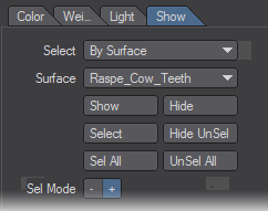
Show / Hide Polygons By Surface
Select By Surface from the Select pop-up menu to manipulate by surface. You’ll also need to select a surface from the Surface pop-up menu.
| Show | shows polygons of selected surface |
| Select | selects polygons of selected surface |
| Hide | hides polygons of selected surface |
| Hide UnSel | hide unselected polygons |
| Sel All | selects shown polygons |
| UnSel All | unselects shown polygons |
Vertex Paint: Light Setting
Setting the Light Source
Setting light sources on the Light tab determines the number of the lights, color properties, position, and other properties used in the “Lighting Shade” display mode. At the same time, it is used for the baking shading color with the Burn Lighting Colors command in the color mode. You can have up to eight different lights
Choosing Light
To choose light, select one from the Name pop-up menu or click the light icon in the 3D view with your LMB, if it’s visible.
Clicking on the checkbox next to the Name pop-up menu activates the light and affects the calculations of the light source on the scene. Click the checkbox off to deactivate the light source. Inactive light sources do not illuminate the scene.
Light Type
In Vertex Paint, you can use distant lights, point lights, and spotlights. You can also set the ambient color for the lights, which affects the entire scene. Below is a table of the parameters available for each light. These are used for OpenGL’s light settings. For more information on the parameters, refer to “OpenGL Programming Guide”, published by Addison Wesley (ISBN: 0-321-17348-1).
| Distant Light | Point Light | Spotlight | |
|---|---|---|---|
| Diffuse | 4 | 4 | 4 |
| Ambient | 4 | 4 | 4 |
| Specular | 4 | 4 | 4 |
| Position | 4 | 4 | 4 |
| Spotlight Position | 7 | 7 | 4 |
| Spotlight Angle | 7 | 7 | 4 |
| Constant Attenuation | 7 | 4 | 4 |
| Linear Attenuation | 7 | 4 | 4 |
| Quadratic Attenuation | 7 | 4 | 4 |
Positioning the Light
To move a light, click on the Position field on the Light tab and enter the coordinates in the dialog that appears. You can also just grab the light in the 3D view with your LMB and drag it to wherever you like.
Distant Light
Generally, a distant light is a light source which you only specify the light direction. In Vertex Paint, the direction of the distant light is measured as a vector from the light Position to the Origin. Moving the light position changes the vector direction.
Point Light
A Point light is a light source that has no direction and illuminates omnidirectionally (in 360 degrees). In Vertex Paint, the position of the point light is specified as the light Position.
Spotlight
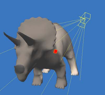
A Spotlight is a light source that has both position and direction information. In Vertex Paint, the position of the light is specified as the light Position and a coordinate where the spotlight “points” is defined by the Spotlight Position. The Spotlight Position is indicated by a red box so you can drag it in the 3D view. Also, the dotted lines coming out of the light represent the spotlight cone angle which can be changed by adjusting the Spotlight Angle setting.
Vertex Paint: Vertex Color Paint
Create Vertex Color Map
To use Vertex Paint, you must define at least one vertex color map before you begin painting. Note that if an object mesh has more than one vertex color map, Vertex Paint uses the first map as the current map.
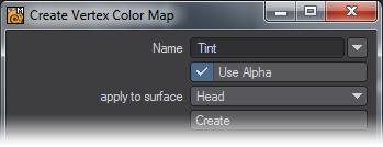
To create a new Color map, select the Color tab, then choose Edit > Create Vertex Color Map. Enter a unique map name and click OK
Rename Vertex Color Map
To rename a vertex color map, select the Color tab and the map, then choose Edit > Rename Vertex Color Map.
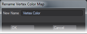
Enter the new name and click OK. Note that you still need to update the object by clicking the Save button next to the Object pop-up menu.
Delete Vertex Color Map
To delete a vertex color map, select the Color tab and the map, then choose Edit > Delete Vertex Color Map. The change is reflected when you click the Save button next to the Object pop-up menu.
Vertex Color Map Type
There are two types of vertex color maps. RGBA means that the map includes the alpha information and RGB means that the map does not include the alpha information. In Vertex Paint, all the vertex color maps are treated as if they include the alpha. You can change the color map type by selecting the pop-up menu next to the Color Map option on the Color tab. The change is reflected when you click the Save button next to the Object pop-up menu.
Component vs. Blending Display
The Vertex Color and Wireframe Color display modes can blend the display of vertex color (RGB) and Vertex alpha data. Clicking the B button on changes display mode to “alpha-blended.” The Vertex Alpha option on the Preference panel determines how to blend the alpha.
If you set the Vertex Alpha option to Surface Color, information on the vertex color’s alpha is displayed as a blended percentage value of the vertex color and surface color - the same way LightWave handles vertex color alpha.
Color.Red = Vertex.Red * Vertex.Alpha + Surface.Red * (1.0 - Vertex.Alpha)Color.Green = Vertex.Green * Vertex.Alpha + Surface.Green * (1.0 - Vertex.Alpha)Color.Blue = Vertex.Blue * Vertex.Alpha + Surface.Blue * (1.0 - Vertex.Alpha)
If you set the Vertex Alpha option to Opacity, information on the vertex color’s alpha is displayed as an opacity value. If the alpha value is 1.0, the vertex color would be completely opaque. If the alpha value is 0.0, then the vertex color would be completely transparent.
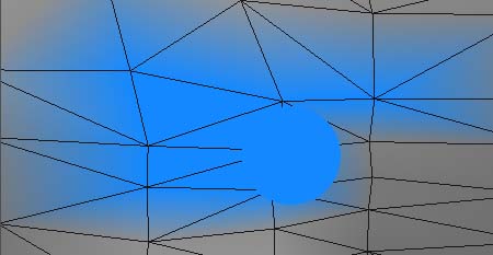
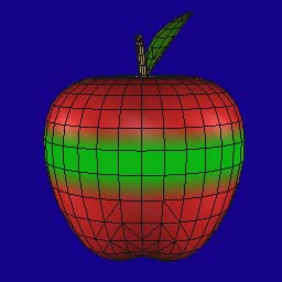 | 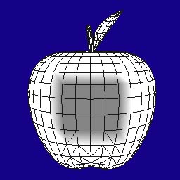 |
| A component display mode using RGB painting. Only the vertex color is displayed. | A component display mode using Alpha painting mode. Only the Alpha luminosity is displayed. |
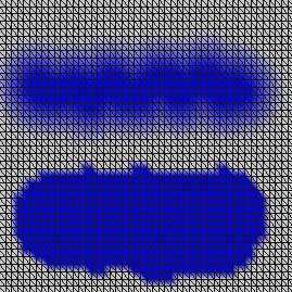
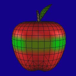 | 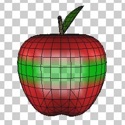 |
| A blended display mode choosing Surface Color for the Vertex Alpha option. Both vertex color and surface color is displayed. | A blended display mode choosing Opacity for the Vertex Alpha option. Vertices with an alpha value less than 1.0 are semi-transparent. |
Vertex Color Painting
Vertex Paint has three painting modes to paint the vertex color using a brush.
- Color / Paint - Paint per point
- Color / Index - Paint per vertex index of polygon
- Color / Polygon - Paint per polygon
To begin painting, select a vertex color map on the Color Map pop-up menu or create a new vertex color map. Dragging your LMB on the 3D view paints points or polygons.
Selecting Operation Mode
There are three operating modes that determine how paint is applied to existing vertex colors.
- ADD - adds the value of the paint color to existing color.
- SUB - subtracts the value of the paint color from existing color.
- REP - replaces the value of existing color with the value of the paint color.
- ERA - sets the value of existing color to 0.
Selecting Component
You have two components for painting vertex color: RGB and Alpha. To switch, click on the color component icon.
 RGB
RGB Alpha
Alpha
Selecting Paint Color
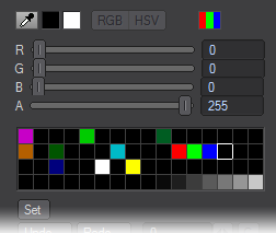
There are two way to choose the paint color: the color slider bar and color palette.The color slider bar has RGB and HSV modes. You can switch modes depending on your needs. The current RGB color is shown on the swatch to the right of the eye dropper icon. The current Alpha is shown on the swatch to the right of the color swatch. Although Vertex Paint internally maintains color using floating values (i.e., 0.0 to 1.0), numerical color values are rounded to the nearest integral value from 0 to 255.
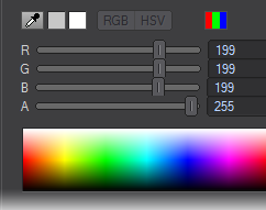
You can choose a color directly by dragging your LMB over the palette, a color is selected when you release your mouse button. To choose an Alpha value, use the slider instead of the palette. You can customise the palette, which is discussed later.
You can also pick any color displayed on the 3D view. Hold the Ctrl and Shift keys, then click on the desired color in the 3D view. Another way to pick a color on the 3D view is to activate the eyedropper icon and drag on the 3D view with your LMB.

You can use the default LightWave color picker to pick a color as well. Clicking on the color swatch with your LMB will launch it.
Painting Vertex Colors on Points
If you choose Color / Point for the Paint mode, you can paint vertex color on points, using three parameters: Brush Size, Front, and Strength.
- Brush Size - Determines the size of your paint brush. You can visually see the brush size when you drag and paint on the 3D view with your LMB . To adjust your brush size, enter a value in the Brush Size input field. You can also adjust the size by dragging your RMB in the 3D view. Release your mouse button to accept the new size.
- Front - Use this option when you do not want to paint points on the opposite side.
- Brush Shape - You can paint with a round or square brush by clicking on the icon to the right of the Brush Size slider.
- Strength - Strength allows you to paint as if you were using a soft brush. If Strength is set to 100%, all painted vertices get the same value. If Strength is set to 0%, the effect of the brush is 100% at its very center, but 0% at its edge. Areas of the brush between the center and edge use a proportionate value.
Top: Strength=25%, Bottom:Strength=100%
Painting Polygon Vertex Indices
If you choose Color / Index for the Paint mode, you can paint the “vertex index” of polygons. The vertex index is a unique reference for each polygon vertex. Although a point may be shared by polygons, the vertex index is different. Just click inside the polygon nearest the vertex you want to affect. Brush Size, Front, and Strength settings are ignored.
Painting Vertex Color per Polygon
If you choose Color / Polygon as the Paint mode, you can paint individual polygons a solid color.
Brush Size, Front and Strength settings are ignored. This essentially sets all of the polygon’s vertex indices to the same value.
Painting Symmetrically along the X Axis
Clicking the symmetry button at the top of the interface lets you to paint symmetrically along the X Axis. If you paint geometry on one side (left or right), all the polygons and points symmetrical along the X axis is painted at the same time. This option can be used with any paint mode.

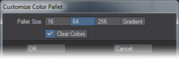
Customising the Color Palette
You can customise your color palette for Vertex Paint by choosing Edit > Customize Color Palette. There are four palettes available: 16, 64, 256, and Gradient, the default. Activating the Clear Colors option erases all existing palette information, resetting the colors to black (0,0,0).
Customized palette information is stored in the preference file. It maintains the information until another palette is loaded or the palette is reset.
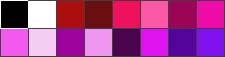
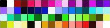
Palette Size = 16
Palette Size = 64
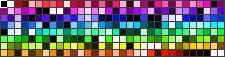
Palette Size = 256
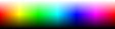
Gradient
To add a color to a swatch in a (non-gradient) palette, first select a swatch with your mouse. Then, adjust the current RGB color values. Finally, click the set button below the palette. The RGB color will be added to the selected palette swatch.

Loading a Color Palette
To load a color palette, with the Color tab selected, choose Edit > Load Color Palette File. Then select a previously saved palette file. The following four formats are supported:8-bit BMP, 8-bit TARGA, Microsoft Palette® (.pal), and ACT color table (.act).
Saving a Color Palette
To save a color palette, with the Color tab selected, choose Edit > Save Color Palette File. The file is saved in Microsoft Palette® format (.pal).
Baking OpenGL Shading)
With Vertex Paint, you can “bake” OpenGL color information (including light source calculation) to a vertex color map. You can see the shading status to be baked using the Lighting Shade display mode. Adjust the light strength, location and other settings on the Light tab before baking.
To bake the colors, first create a vertex color map, then with the Color tab selected, choose Edit > Burn Shading Colors.
You have to set your view so that the entire object is visible in the 3D view. If not, the part outside the view will be omitted from the color calculations, or an error will occur.
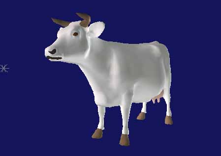
The Lighting Shade display mode. The light source is calculated.
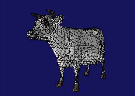
The Wireframe Color display mode, displaying vertex color that was baked by the Burn Shading Colors command.
Reset to Surface Color
Executing “Reset To Surface Colors” from the “Edit” menu resets vertex color to surface color.
Adjusting Vertex
Vertex Paint has several tools for adjusting vertex colors baked by Burn Shading Colors or the Shader Baker layout plugin.
Adjusting Brightness and Contrast
With the Color tab selected, choosing Edit > Brightness/Contrast displays the following dialog box, where you can adjust brightness and contrast.
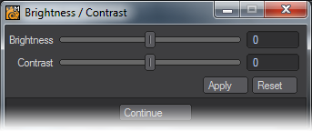
When you move the sliders, the change in brightness or contrast is previewd on the display in realtime. However, the change is not saved until you click the Apply button.
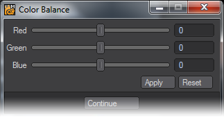
Adjusting Balance
With the Color tab selected, choosing Edit > Color Balance displays the following dialog box, where you can adjust each RGB component separately.
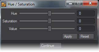
Adjusting Hue, Saturation and Value
With the Color tab selected, choosing Edit > Hue/Saturation displays the following dialog box, where you can adjust hue, saturation and value.
Vertex Paint: Bone Weight Paint
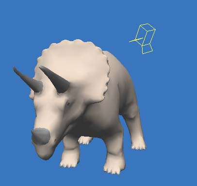
Choosing Bones
There are three ways to select the current bone, which becomes highlighted in yellow:
- With the Weight tab selected, select the bone name from the Bone pop-up menu.
- Press the Up or Down cursor key to choose the next or previous bone until you get the desired one.
- Hold the Shift key and click the desired bone with your LMB directly in the 3D view.
It may be difficult to choose a bone in the 3D view when it is inside the mesh. In such cases, disable Hide Unselected Bones on the Preferences panel. This shows the unselected bones outside the object so they are easily selected.
Disabling “Hide Unselected Bones” shows the bones
Also, you can work with bones easier when they are centered in the 3D view. To do this, just press the A key or select Fit Bone from the pop-up menu (small button with down arrowhead) along the top of the main interface.
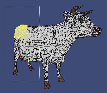
Displaying Weight
There are two display modes for bone weight: Weight Value and Weight Ratio.
Weight Value display mode
Weight Value displays the value of the weight map that belongs to the current bone using a red gradient. Areas displayed in grey have no weight, or are just slightly weighted. This mode is useful when you are painting the weight. You can adjust the density of color using the Color Scale option on the Paint tab.
You can also set the default value for Color Scale with the Weight Color Scale setting on the Preference panel.
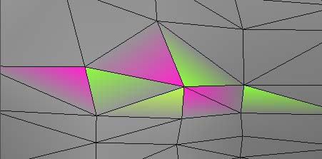
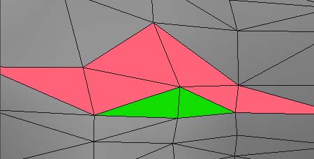
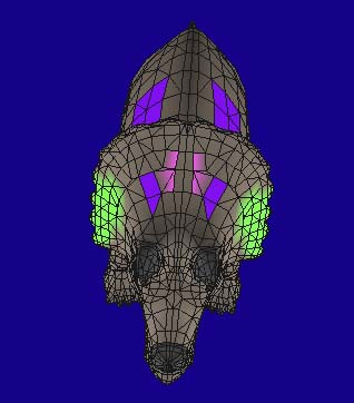
Weight Ratio display mode
Weight Ratio is a mode that displays the ratio of bones’ influence on each point. Red, blue and green are preset for each bone; however, you can reset the colors using the color icon next to the Bone name pop-up menu.
“Bone Color” icon
Renaming Bones
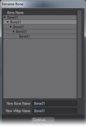
To rename bones, choose Edit > Rename Bone with the Weight tab selected. A bone tree, like the one shown below appears. Select the bone you want to rename with your LMB and enter a name in the New Bone Name field. You can also rename the weight map name (New VMap Name field) at the same time.
The bones are displayed in a hierarchical order. Bone visible in the 3D view will be updated in real time. Also, the bone selected here becomes the current bone.
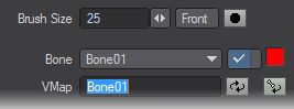
Renaming Weight Maps
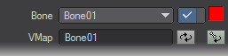
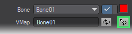
To rename a weight map, enter new name in VMap field. Don’t forget to save your changes.
You might see the following dialog box when you try to rename a VMap. This box appears when one weight VMap is already used (shared) by one or more other bones. If you click Yes, all of the VMap names used for the bones that refer to this VMap will be renamed. If you click No, only the VMap which the current bone refers to will be renamed - if no such VMap already exists, a new one will be created.
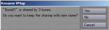
This panel shows that three bones share one name “Bone01.” So if you click Yes, all three bones that referred to VMap “Bone01” will refer to newly renamed VMaps.
Copying Weight
You can copy a value of the weight map that belongs to the current bone to the Vertex Paint clipboard buffer. Press the C key or choose Edit > Copy. No message will be shown.
Pasting Weight
You can paste the copied weight value from the clipboard buffer to another bone’s weight map. Press the V key or choose Edit > Paste.
Pasting Weight Symmetrically in X Axis
You can paste the copied weight value from the clipboard buffer to another bone’s weight map along the X axis symmetrically. Press the V key or choose Edit > Paste-X. The point located symmetrical along the X axis is found and weight map value is set.
You can specify the amount of “calculation error” when finding the symmetrical point with the Mirror Epsilon setting on the Preference panel.
Pasting Weight Symmetrically Along an Arbitrary Axis
You can paste the copied weight value from the clipboard buffer to another bone’s weight map symmetrically along an arbitrary axis. Choose Edit > Paste-Axis to display the panel shown below. Select the desired Axis and offset Position. Then click OK.
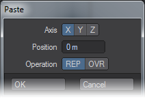
Axis
Specifies the axis which the weight is to be pasted symmetrically. If you choose X, all of the points that meet the condition “X’ = -X” is looked up.
PositionSpecifies the origin position. If you selected the X Axis and then set Position to 1m, all of the points that meet the condition “X’ = -X + 2m” is looked up. OperationSpecifies how the weight will be pasted to the points. REP replaces the whole original weight value with the new value. OVR overwrites part of the original value only if the new value is bigger than the original ones.
Using the OVR option allows you to paste the map symmetrically onto the same weight VMap. To do this, copy the weight and then paste it to the same weight VMap using the OVR option, you can create a weight map symmetrical to itself.
Normalising Weights
Sometimes you may get excessive weight values from using the BoneWeight Modeler command or just from painting in Vertex Paint. Weight values go beyond the normal range 0.0 to 1.0. Bone deformation can deform without “normalising” the weight because it is performed relatively, that is, using the percentage of the weight. However, in some cases (such as adjusting the weight by painting), you may want to normalize the weight to give you better control. Choose Edit > Normalize to normalize the weight values between 0.0 and 1.0, according to their percentages.
A weight map that is not normalised
A weight map that is normalised
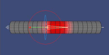
Trimming Weight
Bones inside “branching-type” geometry, like fingers, can be problematic when the weight map is created using a falloff calculation without any correction. Bone deformation will likely affect areas you wish to be independent. This is because the falloff calculation is performed referring to only the distance between a bone and a point.
The Edit > Trim Branch function solves the problem by allowing you to trim the weight for the current weight map. It first calculates the “primary bone” for each point (i.e., the bone closest to the point). If the bone is not a descendant of the current bone, the weight map value that the point holds is cleared. “A descendant” is a “bone route path” generated from one parent.
If you use this command where the bone route path branches, like at the base of a finger, it may not deform smoothly. As such, try to use this command where there is not bone branching. Also, trimming may not work well depending on the bone location. If you encounter this problem, try using the ERA or SUB painting operations to adjust the weight value.
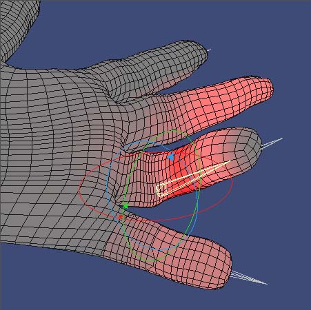
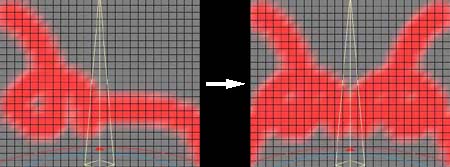
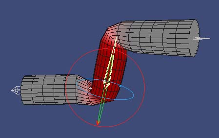
Before using Trim Branch. If you bend the finger using the highlighted bone, neighbouring fingers will also bend because they have bone weight.
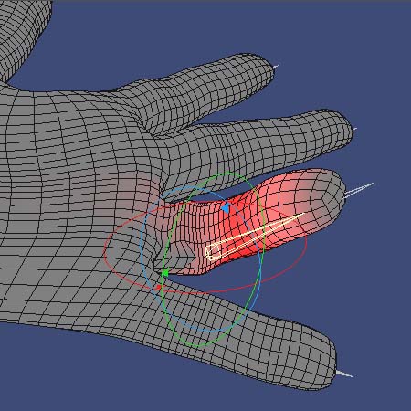
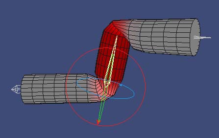
After using Trim Branch. Unnecessary weight for the points on neighbouring fingers have been erased. You can now bend the finger independently.
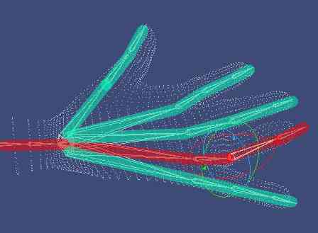
Bones on the red line represent a descendant of the current bone, and bones on the blue line represents the other descendants.
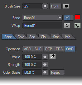
Painting Weight
Select the Paint subtab on the Weight tab to “paint weight.” There are some adjustable parameters that will determine how the effect is applied. Dragging in the 3D view with your LMB paints the points under your mouse pointer.
The Brush Size and the Front settings are shared with the vertex color painting operations.
Operation
Specify how the point weight is applied:
- ADD - This mode adds the Value to the painted target weight. Note that the operation is only applied once while you press the mouse button, start dragging, and then release the button.
- SUB - This mode subtracts the Value from the painted target weight. Note that the operation is only applied once while you press the mouse button, start dragging, and then release the button.
- REP - This mode replaces the painted target weight with the Value.
- ERA - This mode sets the painted target weight to 0.0.
- OVR - This mode replaces the weight only if the Value setting is larger than the painted target weight value.
- Value - This specifies the weight value that you are going to paint. A value of 100% is internally converted to 1.0 as a weight value. When you activate the picker button, you can refer to the weight value in the 3D view. Dragging your LMB refers to a weight value of the point that is closest to your mouse pointer.
Strength
Strength sets the point from the center of the brush where the paint falls off. If Strength is 100%, points inside the brush are all painted with a the full Value. If Strength is 0%, the center of the brush is painted with 100% of strength, and the value decreases relatively from from the center to the outer edge of the brush. If Strength is 50%, points within half the radius receive the full Value, then it falls off toward the edge of the brush.
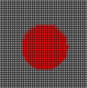
Strength = 100%. All the point inside the brush is painted with the same value.
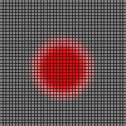
Strength = 50%. Points inside half the radius are painted with 100% of the Value, then decreases relative to the distance from the center.
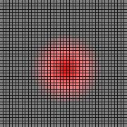
Strength = 0%. The paint strength decreases relative to the distance from the center of the brush.
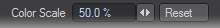
Color Scale
This adjusts the strength of red gradient color in the Weight Value display mode. This is only a display setting, so changing this value does not affect the actual weight value.
Calculating Weight
To calculate weight using a falloff, select the Calc subtab on the Weight tab. Basically, this function works the same as the Modeler plugin Bone Weight. Note that any weight calculations will be normalized.
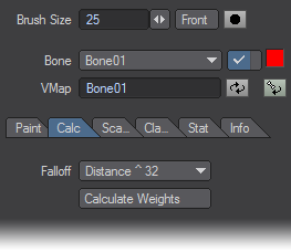
Falloff specifies how the weight value is calculated. Linear sets the bone weight closest to the point to 1.0. Other weight is set to 0.0. Distance uses the inverse of the distance from point to bone as weight value. Other options (e.g., Distance ^ 32) use the distance raised to a specific power. Higher powers cause a quicker falloff.
Calculate Weights executes the calculation based on the settings you have chosen.
Scaling Weight
To scale weight values, select the Scale subtab on the Weight tab.
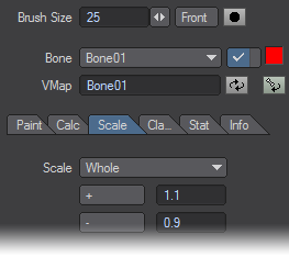
The Scale setting specifies how the weight values are scaled.
| Whole | Scales all weight value uniformly |
| At Start Joint | Scales values using the bone’s starting point (the fat end) as the center |
| At End Joint | Scales values using the bone’s ending point (the sharp end) as the center. |
Click the + button to scale up the weight values using the value set in the input field next to the button. You can also scale it up by pressing the “+” key. Click the - button to scale down the weight value using the value set in the input field next to the button. You can also scale it down by pressing the “-” key.
Whole
Scales all weight value uniformly.
At Start Joint
Scales values using the bone’s starting point (the fat end) as the center.
At End Joint
Scales values using the bone’s ending point (the sharp end) as the center.
Left: A weight map scaled up from the bone’s starting point. Right: A weight map scaled up from the bone’s ending point
Clamping WeightTo clamp the weight, select the Clamp subtab on the Weight tab. When you deform single-mesh objects using bones, the more bones you have, the slower the calculation speed. By discarding the weight value for bones that have little influence, the calculation speed will be improved. This can be one of the most important factors in single-mesh realtime animations.
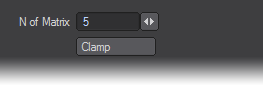
The N of Matrix setting corresponds to the number of bones that are sorted by their strength of influence. Let’s say you have a mesh with twenty bones. If you set N of Matrix to 5 and then press Clamp, up to the top five strongest weight values of the bones (for each bone) are retained. The other values (that is, values of the bones with weak influence) are set to 0.0.
Viewing Weight Statistics
Use the Weight Statistics tab to select weighted points based on a value. These can be removed from the map to increase efficiency. To view weight statistics, select the Stat subtab on the Weight tab.
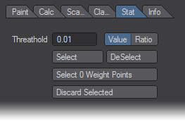
The Threshold setting specifies the threshold for selecting points. The buttons to the right of the input field represent the units. Value means the actual weight value. Ratio means a normalized range from 0.0 to 1.0.
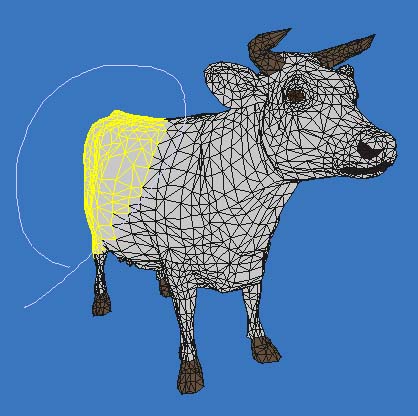
Clicking the Select button will highlight in yellow the points which have a weight value less than the Threshold. To deselect, click the DeSelect button.
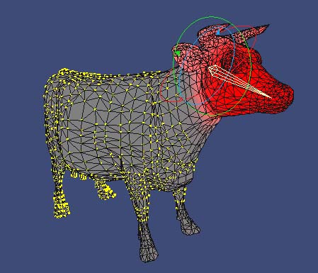
The Select 0 Weight Points button detects zero-weighted points.The Discard Selected button removes the map from the selected points.
Setting Weight Value
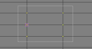
To set the weight value for individual points, select the Info subtab on the Weight tab.
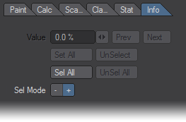
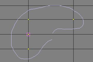
Selecting/Deselecting Points
By default, no points are selected. There are several ways to select points to edit.
- To select all points - Click the Sel All button to select all points. Press the UnSel All button to deselect all points.
- To use your mouse pointer - Drag your LMB in the 3D view to select points.
- To select using a bounding box - Hold the Ctrl and Shift keys and drag a bounding box with your LMB in the 3D view. Points included in this bounding box are selected when you release your mouse button.
- To select using lasso - Hold the Ctrl and Shift keys and drag your RMB in the 3D view. Points within the lassoed area are selected when you release your mouse button.
You can use the Sel Mode setting to switch between Select ( + ) and Deselect ( - ) modes. You can also switch modes by hitting the Space key.
Clicking the UnSelect button deselects the current editable point (pink square).
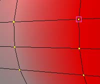
The Current Editable Point
Selected points are shown as a yellow point, and the current editable point is surrounded by a small pink square.
The value of the current editable point is displayed in the Value field. You can change the weight value by dragging the slider or entering a value directly. You can cycling through all of the selected points, to change the current editable point, by clicking the Prev and Next buttons. The number of points selected and the (reference) number for the current editable point is displayed in the information display field at the bottom.
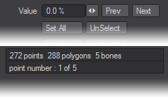
Setting Weight Value
To specify the weight value for all selected points, enter a number in the Value field and click the Set All button.
Editing the Bank Rotation Axis of Skelegons
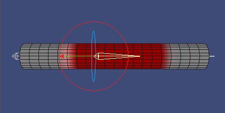
Skelegons generated in Modeler have vector information for the bank rotation axis that refers to the upward direction. This determines the bank rotation angle of the bone when converted in Layout. To adjust the bank rotation axis in Vertex Paint, activate the Bank Rotation Axis Edit option. (Note: Vertex Paint will reset all skelegons to their rest position before allowing you to edit the bank rotation.)
Hold the Ctrl key and drag your LMB in the 3D view. A thick blue ring represents the bank rotation. The arrow represents the “upward direction” of the skelegon.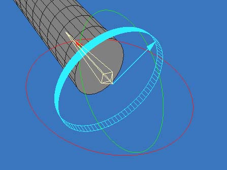
This editing option is only available for Modeler’s skelegons. You cannot use this option on the bones loaded by Vertex Loader.
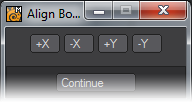
If you want the bank rotation axis to align to a specified axis precisely, press the N key. The bank rotation axis will correspond to the axis you chose.
Vertex Paint: Creating a Morph Target
To create a new morph target, choose (new) from the Morph pop-up menu on the main panel. A dialog will appear where you indicate the Name and Type of morph target.
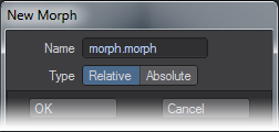
If you enter a new name when creating a morph target, geometry with bone deformation (from rotation, move, and scale) in the 3D view is created. Deformed geometry created using the preview animation function can also be used.
Vertex Paint: Misc
Import/Export Vertex Paint 1.0 file
The Import… and Export… items on the File menu can be used to import/export the Vertex Paint 1.0 format of the vertex color file (.vcl). (Vertex Paint 1.0 came with LightWave 5.6)
Loading a Vertex Color file (.vcl) into Vertex Paint
You must first load the LightWave 5.6 format LWO file into Modeler before loading the vertex color file (.vcl). Then start Vertex Paint. Create a new vertex color map by choosing Edit > Create Vertex Color Map and then choose File > Import…. Select a .vcl file associated with the loaded lwo file on the file dialog.
Saving the Current Vertex Color Map to a .vcl File
Select the vertex color map you want to save and choose File > Export…. Enter a name in the file dialog and click Save.
Preference Panel
You can define some default setting on the Preferences panel (File > Preferences). Note that some changes will not take effect until the next time you launch Vertex Paint.
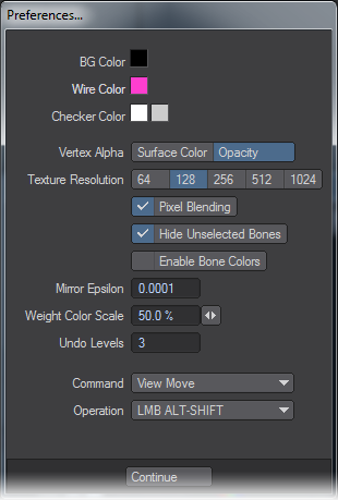
BG Color
BG Color specifies the background color. Clicking on the color box with your LMB displays the standard LightWave color picker. The change is applied when you close the Preferences panel. (Note: If your display does not update, try clicking in the 3D window.)
Wire Color
Wire Color specifies the wireframe line color. Clicking on the color box with your LMB displays the standard LightWave color picker. This setting affects the Wireframe Color, Weight Value,and Weight Ratio display modes. The change is applied when you close the Preferences panel. (Note: If your display does not update, try clicking in the 3D window.)
Checker Color
The two Checker Color boxes specifies the colors used for the checker pattern that makes up the background in the blending display mode. Clicking either of the color boxes displays the standard LightWave color picker.
Vertex Alpha
Vertex Alpha determines how the vertex color’s alpha information is displayed in the Vertex Color and Wireframe Color display modes. If you select Surface Color, information on the vertex color’s alpha is treated as a value of blended percentage of vertex color and surface color. If you select Opacity, information on the vertex color’s alpha is displayed as a value of opacity.
Texture Resolution
Texture Resolution determines the texture resolution displayed in the Vertex Color, Wireframe Color and Lighting Shade display modes.
Pixel Blending
If Pixel Blending is active, both texture color and vertex color (or surface color) are displayed together. If Pixel Blending is inactive, texture color overrides the vertex color and Vertex Paint only displays texture color.
Hide Unselected Bones
Hide Unselected Bones specifies the display mode for unselected bones. If this option is active, unselected bones hide behind the objects. If this option is inactive, unselected bones are shown in front of the object so that you can grab and control them more easily.
Enable Bone Colors
If Enable Bone Colors is active, bone geometry is displayed using the Weight Ratio color.
Mirror Epsilon
Mirror Epsilon determines the accuracy used when Vertex Paint searches the axis-symmetry point for the Symmetry mode, and the Paste-X and Paste-Axis options. The smaller value you set, the more precise the symmetry point are searched.
Weight Color Scale
Weight Color Scale determines the default value of the color scale used for the Weight Value display mode.
Undo Levels
Undo Levels specifies the maximum number of undos in the Color and the Weight display modes. Higher values require more memory.
Command / Operation
Select desired setting from those pop-up menu when you want to customise the default mouse operations. Assign each Operation setting to each Command setting.
Frequently Asked Questions
Q. Does Vertex Paint work with SubPatch objects? A. Yes. A SubPatch mesh is displayed as a polygon mesh. Vertex Paint can edit the required VMAP information. The original SubPatch information is maintained after it is modified.
Q. I cannot paint vertex colors. A. One or more vertex color maps are required to paint vertex colors. To create one, with the Color tab selected, choose Edit > Create Vertex Color Map.
Q. An error “Unable to burn render colors.” occurs when I try to bake vertex colors. A. The Burn Shading Colors command uses OpenGL functions to acquire the color that is currently displayed. Therefore, Vertex Paint will not work properly if there is anything covering the 3D view or the object is outside the 3D view. Put the object inside the view and try again.
Q. I created a vertex color map but the vertex color is not displayed in Modeler. A. You have to assign the vertex color map to a surface. To do this, specify the map for the Vertex Color Map setting on the Surface Editor’s Advanced tab.
Q. Does Vertex Paint work with Layout in real time via the HUB? A. Clicking Vertex Paint’s Save button overwrites modified weight value and/or vertex color in Modeler. The changes should be reflected on the object in Layout after saving. (Note: Conversely, Vertex Paint does not acquire surface properties changed in Layout.)
Q. Can I utilise information such as vertex color for game development? A. You can access information, such as vertex color, by using the LightWave 8.0 plugin SDK. Other information, such as UV map and bone weight, can be acquired from both Modeler and Layout.You also can download Object Library 2 from DStorm to convert vertex color information stored in a LWO file. This could be used for something like in-house tool development.