Falloff Mode
Several of the tools on the Modify tab have a Falloff pop-up menu on the lower half of the numeric panels. By changing the Falloff setting, you can effectively make the function of the Move tool have the same effects as using the Shear, Magnet, DragNet, and Drag tools, by just changing its Falloff setting. You might think of these tools as just shortcuts to a defined group of Modify settings. This type of selection via falloffs is also referred to as a Soft Selection.
We will be explaining the falloff tools here at the start of the chapter.
Falloff Types
- None - None means no falloff. The Move tool is set to this by default.
- Linear - Linear makes the effect fall off along a linear axis, and operates like the tools Shear, Twist, Taper1, and Taper2.
- Point - Point falloff works like the Drag tool.
- Point Radial - Point Radial operates much like the DragNet tool.
- Polygon - Polygon means falloff is immediate around a polygon, so you can move only a single polygon. It behaves like the drag tool but works on single polygons instead of points.
- Radial - Radial means the effect will fall off in a radial pattern (in a cylindrical or spherical shape), so it is the default for Magnet, Vortex , Pole1, and Pole2.
- Weight Map - Weight Map uses the selected Weight Map for the falloff. Unweighted points will not move at all, while heavily weighted points will move the most. Negatively weighted points will move inversely. This allows you to use an irregularly shaped falloff. This mode is particularly useful for creating facial endomorphs.
Falloff Mouse Controls
Falloffs are controlled with the right mouse button (RMB).
- RMB on a handle to drag it.
- RMB on nothing to start a new falloff.
- RMB-Click on the handle to switch to Auto falloff mode.
- Holding down Ctrl constrains the dragging of falloff handles to horizontal axes.
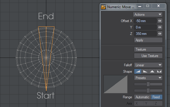
Linear Settings
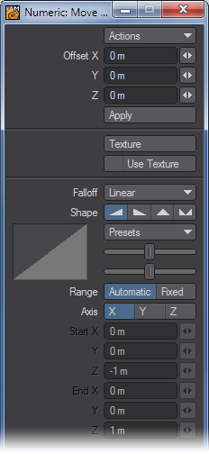
Shape
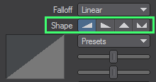
You can quickly select between various basic falloff directions using the Shape buttons. The Shape setting determines the Area of Influence. This is shown graphically in both the numeric panel and viewport windows. You can also use the Left and Right cursor keys to change the selected Shape.
Tension Sliders
You can adjust how the effect falls off using the two sliders, which act like tension spline controls for the beginning (upper slider) and ending (lower slider).
Presets
You can quickly set up some common curves by selecting from the Preset pop-up menu. The graph on the numeric panel, as well as the outer edges of the axis tree (when using a fixed range) gives you a visual picture of the falloff. You can also use the Up and Down cursor keys to cycle through the Preset selection.
Range
The Range option determines where the Falloff’s center is located. By default, a linear falloff tool’s effect is automatically applied to the object (or selected items) 100 percent at one end and zero at the other, along the axis perpendicular to the editing viewport. This is indicated by the Range option at the bottom portion of the numeric panel, which has Automatic selected.
To use the tool in the Automatic mode via the numeric panel (by clicking the Apply button), select the perpendicular Axis. (If the axis has not been set either manually or by a previous mouse-based modify operation, the Axis setting is used to compute the falloff when you click Apply.)
- Automatic - The center is set by clicking in the viewport.
- Fixed - The center is set by entering in values in the numeric window.
Using the Automatic Range is the simplest method. Thus, if possible, model your object along one of the three axes.
Instead of using an Automatic Range, you can define a specific Fixed Range using an axis tree. This type of Range can be placed at any position and at any angle in 3D space. The effect tree looks like a pair of crossed wedges. The tool’s effect is applied along this tree with zero at its tip and 100 percent at its base (fat end) - portions of the object beyond the base are still affected 100 percent. The edges of the tree reflect the fall-off curve shape.
To create a fixed range:
- Select the desired linear falloff tool and drag out the axis tree with your RMB. (The Range option will be set to Fixed on the numeric panel.)
- Reposition the ends by dragging them with your RMB .
The XYZ positions of the starting and ending points are reflected in the numeric panel. You can edit these values, if necessary.
To reset to Automatic Range:
To reset to Automatic Range, click your mouse pointer on an inactive interface area. Note this will also switch you back to the Automatic Range mode.
Moving an Object on an Arbitrary Axis
Let’s say you had an object that was not aligned nicely along the X, Y, or Z axis. If you wanted, you could define a fixed range and align the effect tree with the object. However, this can be a tedious process. A better alternative would be to use a Perspective viewport.
Remember, editing generally occurs along a viewport’s arbitrary horizontal and vertical axes. When using a Perspective viewport, this can be something other than directly along the X, Y, or Z axis. Thus, you can align your object so that it is perpendicular in the viewport and just use the Automatic Range.
Radial Settings:
This influence area falls off in a radial pattern (a sphere or cylinder). It is set independently of any selected polygons or points, but works in conjunction with them. That is, if points/polygons are selected, only those within the influence area are affected.
By default, the tool’s effect is automatically applied to the entire object (or selected items). This is indicated by the Range option, at the bottom portion of the numeric panel, which will have Automatic selected.
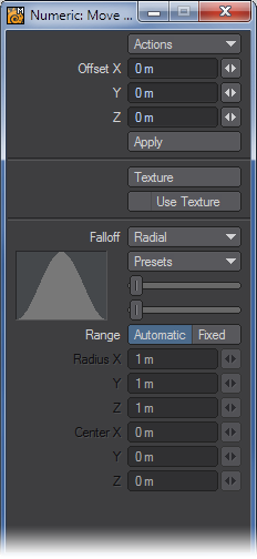
Setting the Falloff Shape
How the effect falls off is determined by the two sliders, which act like tension spline controls for the beginning/end (upper slider) and center (lower slider). You can quickly set up some common curves by selecting from the Preset pop-up menu. The graph gives you a visual picture of the falloff.
Defining a Specific Range
Instead of using an Automatic Range, you can define a specific Fixed Range, which can be positioned and sized anywhere in 3D space.
To set the influence area:
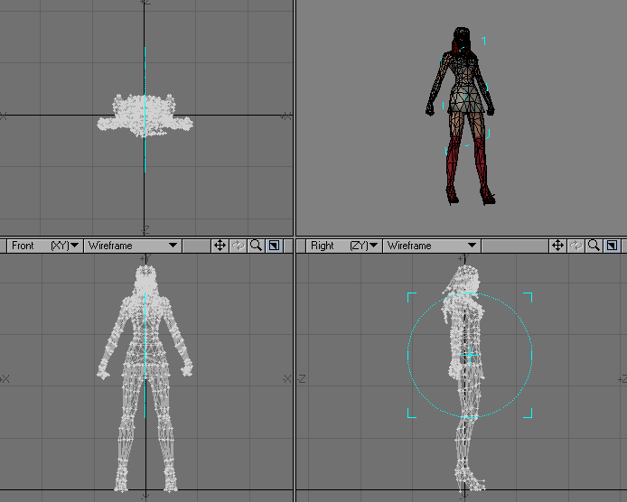
- Select the desired Radial falloff tool and drag out the influence area tree with your RMB . (The Range option will be set to Fixed on the numeric panel.) At this point, you have defined a cylindrical area that extends infinitely along an axis perpendicular to the viewport. Use the Ctrl key to constrain to a circle.
- Resize the initial area as needed by dragging the outline edge handles with your RMB or reposition by dragging the center handle.
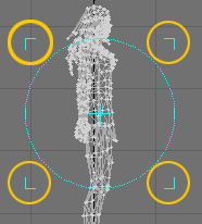
- To limit the depth of the area, drag out the outline in a different viewport. The amount of influence is strongest at the center and diminishes towards the edges. Polygons with all points outside of the area will not be affected.
Creating the radial falloff influence area is similar to creating a Box primitive, particularly in a perspective viewport.
To reset the influence area:
To reset the influence area, click your mouse pointer on an inactive interface area. Note this will also switch you back to the Automatic Range mode.
The Numeric Panel
The Radius X, Y, and Z values reflect the size and shape of the influence area. If you have defined a cylindrical (i.e., two-dimensional) area, one axis will be 0. The Center X, Y, and Z values define the center of the area of influence.
Texture added to Falloffs
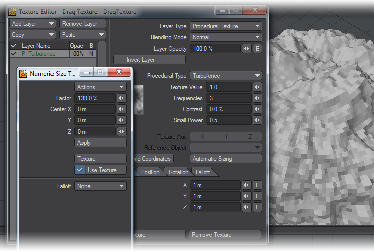
Texture was added to the Falloff options in Modeler 2015 for the Move, Dragnet, Rotate, Scale, Shear and Twist tools. The texture can be chosen with a click on the Texture button (Image maps, Gradients and procedural textures including Nodes can all be used) and clicking on the Use Texture toggle will use the Texture falloff or revert to one of the standard Falloffs at the bottom of the window.