Duplicate - More
This group contain tools that are no longer so required, but could still prove useful in the right circumstances.
Particle Clone
Particle Clone (Multiply > Duplicate > More > Particle Clone) will make a copy of the foreground object on each point that makes up the background object. It’s great for asteroids, bubbles, spikes, grass, etc.
Using Particle Clone:
- Place the object that you would like to clone in the Foreground layer and the object that has the point information in the Background layer.
- Choose Multiply > Duplicate > More > Particle Clone , and sit back and enjoy the magic!
If no object is in the Background layer, Particle Clone will clone the object in the Foreground layer using the points that make up that object.
Point Clone Plus (Multiply > Duplicate > More > Point Clone Plus) performs the same task but has options.
Clone to Layer
The Clone to Layer command (Multiply > Duplicate > More > Clone to Layer) creates copies of an item that you can spread out in an even layout or array. You can create a series of copies along an axis at specified increments. Clone to Layer duplicates a selected item one or more times using specific increments of distance, rotation, and scaling. You can create a spiral staircase out of a single step, or a wood screw out of a triangular polygon outline, for example.


This command is almost identical to the standard Clone (Multiply > Duplicate > Clone) command, but offers the ability to place your cloned geometry in multiple layers.
Clone to Layer Numeric Options:

- Number of Clones - Enter the number of copies of the selection to create in the Number of Clones fields.
- Clone Output - Choose between Current Layer and Multi- Layer.
- Current Layer - This option will place the clones in the same layer as the original.
- Multi-Layer - This option will place the clones in individual layers.
Select the Use Only Empty Layers option to skip over layers that contain data when clones are being created.
The Offset fields determine the incremental distance between one clone and the next along the X, Y, and Z axes.
The Scale fields set the amount of incremental scaling for each copy along the X, Y, and Z axes. The Rotation fields set the amount of incremental rotating around the Heading, Pitch, and Bank.
The effect is progressive, so the change is applied to each clone based on the previous clone. So, for example, with scaling, the copies will get progressively larger or smaller.
The Center Around option consists of Origin (0,0,0), the object’s center, and User Definable.
The Center fields define the coordinates to use as the center point, around which the operation takes place.
If you plan to clone with rotation, try to build your base object so that the rotation can happen around the Origin whenever possible.

To evenly space objects around an axis, take the number of total objects you want to end up with and divide it into 360 (you can even enter the sum into the input field.) This gives you the incremental rotation. Then set the Number of Clones to the total objects minus one.
Motion Path Clone Tool
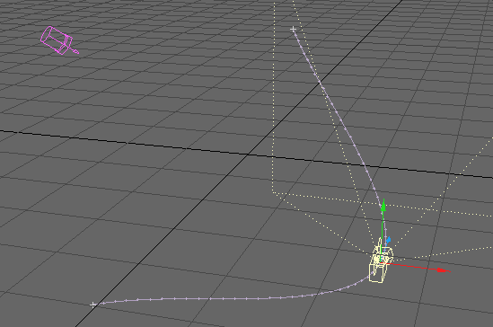
The Path Clone command (Multiply > Duplicate > More > Motion Path Clone) works just like the Path Extrude command, however, instead of resulting in an object with a smooth skin, it creates skinless segment clones along the motion path. Motion Path Clone will create clones of the selected geometry along the chosen motion path.
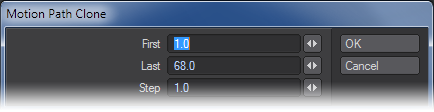
- First: This option defines the first frame in the motion file that will be used.
- Last: This option defines the last frame in the motion file that will be used.
- Step: This option determines how many clones will be used in the extrusion per frame. The lower the number the more segments.
Step Examples:
First Frame 1, Last Frame 60
Step 0.5 - 120 clones
Step 1 - 60 clones
Step 2 - 30 clones
Step 3 - 20 clones
Steps to extrude along a motion path:
- Create a motion path for an item in Layout.
- With the item still selected go to File/Save/Save motion file. Be sure the file has the .mot extension.
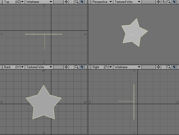
- Open the Modeler and create an object.
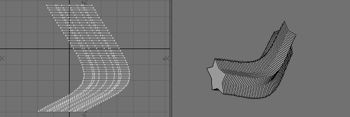
- Select Motion Path Clone ( Multiply > Duplicate > More > Motion Path Clone). Select the path saved above and change settings in the numeric window as needed.
- Click OK.
Symmetrize Tool
The Symmetrize command (Multiply > Duplicate > More > Symmetrize) clones an object n times with a rotation each time so that the result displays n-fold symmetry about the selected Axis. An object is said to have n-fold symmetry if it looks the same after being rotated 360/n degrees.
Point Clone Plus Tool
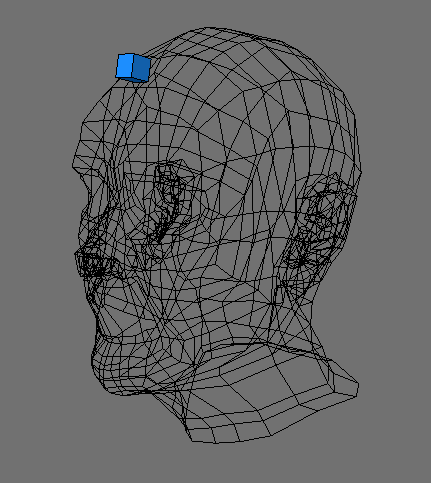
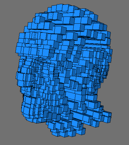
The Point Clone Plus command (Multiply > Duplicate > More > Point Clone Plus) will clone objects in the foreground to the locations of points in the background. You can randomize the rotation, scale, and centring independently for every axis between two values. Random Size will randomly change the overall scaling of objects. The XYZ Axis options specify whether the objects should be centered on the points or flush on one side or another. To specify static values, enter the same number in the Min and Max fields.
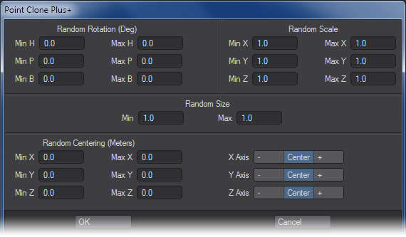
This command is great for cloning and placing, say, tree objects on a landscape or putting hair on a head.


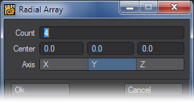
Radial Array
Radial Array (Multiply > Duplicate > More > Radial Array) creates an array of geometry around the Center position using the specified Axis. The Count setting sets the number in the final array.


This is a non-interactive command so you will need to numerically input the settings.
Helix Tool
The Helix Object function (Multiply > Duplicate > More > Helix) will create a helix (or double helix) based on a shape you have modeled. To use it, create your initial geometry and then call the Helix command.

The controls are as follows:
- Number of Rotations - This is how many complete rotations of the spline forming your helix you will have.
- Clones Per Rotation - There are two choices in the dropdown -
- Uniform - The Numeric field below is ghosted and as many clones of your original geometry are made as necessary to ensure a continuous line of geometry along the spline with no gaps.
- User Defined - The Numeric field becomes available for input. The number entered is how many clones of your geometry are used for each 360° section of the helix.
- Helix Radius - The width from the center of the helix to the outside.
- Helix Height - How tall the helix is.
- Taper - This determines how the helix will change shape over its length. A negative number will result in a taper towards the top of the helix, while a positive number will taper towards the base.
- Double Helix - This checkmark will create two similar helices twisting around each other, much like the famous example of DNA.
- Oriented - This will orient your shape to best match the curve of the helix.
The Helix tool can need some clean-up once the operation has been made, including deleting extraneous clones made of the original geometry.


Double Helix and Oriented results in this shape, but the helices meet at the top and bottom, so it's best to remove those cubes.
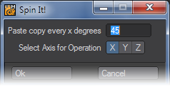
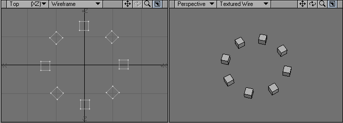
Spin It Tool
The Spin it command (Multiply > Duplicate > More > Spin it) will create an array of geometry around the Origin using the specified Axis.