Bevel Tool
(default keyboard shortcut B)
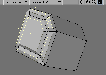
The Bevel tool (Multiply > Extend > Bevel) is likely one of the most commonly used Modeling functions. Basically, it takes a polygon and extrudes it away from the original along the surface normal. It is similar to using the Extrude tool, but there will be no polygon at the position of the original polygon. When applied to multiple polygons, each polygon receives its own bevel - even on a double-sided polygon.
Steps for Beveling a Polygon:
- Select the polygon(s) you would like to Bevel.
- Left-click and drag to create a bevel.
Dragging your pointer after activating the tool lets you graphically place the bevel. Deactivating Bevel or selecting another tool makes the bevel. Click on an open area of the interface to cancel the bevel before it is made or use Undo.
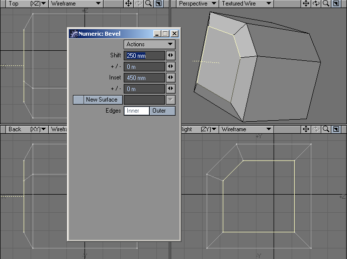
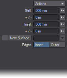
Dragging up/down lets you interactively change the Shift amount, the distance that the selected polygon will move along its surface normal. On the numeric panel, positive values make the bevel move in the same direction as the normal. Negative values make it move in the opposite direction.Dragging left/right lets you interactively change the Inset amount, the distance that the edges of the polygon will move in the same plane as the polygon. On the numeric panel, positive values move inward and negative values move outward.
Drag at an angle to simultaneously change Shift and Inset. Hold the Ctrl key to constrain to Shift or Inset, depending on which direction you drag initially.
If you select polygon(s), the top polygon will remain selected so you can perform bevel operations one after another. Click your RMB to accept the current bevel and begin a new bevel operation. You can also press the B key twice to make and start a new bevel. You can also bevel multiple polygons simultaneously!
Other Numeric Options
The +/- fields on the numeric panel let you set randomization for the Inset and Shift values. The actual value applied will be varied by a random number between plus or minus the +/- value. For example, if Inset was 20 m and its +/- was 5 m, then the actual Inset would be between 15 and 25 meters. Generally, you want to use this feature only when beveling many polygons simultaneously.
To avoid negative random values, make sure the +/-value is always less than or equal to the related Inset or Shift value.
Inner is the default Edges setting and bevels the polygon inward and forward along the surface normal. Outer will bevel outward and backward; however, the original polygon does not move and the new beveled edges extend away from the surface normal. This option reverses the mouse movement effects. In most cases, you use Inner.
By default, the surface name of the source polygon is used for the new geometry. If you select New Surface, you can enter a surface name (even an existing one) in the input field. You can change this setting anytime before accepting the bevel.
The selected polygon retains its surface name; only the new edge polygons receive the defined name.
Beveling Tips
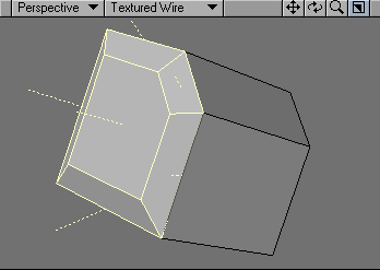
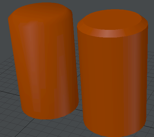
After performing a bevel, the selected polygon remains selected. To accentuate the beveled edge when the surface uses the Smoothing Surface option, perform a quick cut and paste to separate the selected (top) polygon from the added sides. This action precludes LightWave from smoothing over the beveled edge. You may also want to cut and paste the original polygon (before performing the bevel). Make sure you do not merge points after doing this!
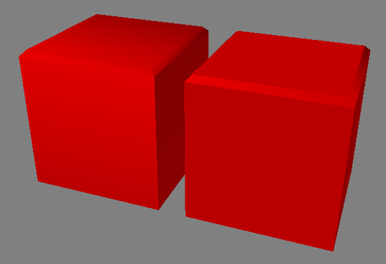
Left: Polygons Not Separated, Right: Polygons Separated
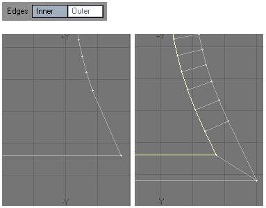
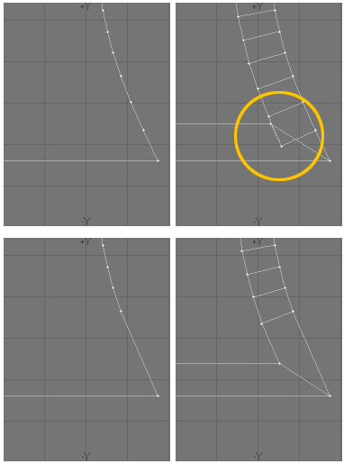
If you use the same surface, which uses Smoothing, and the geometry goes from straight to curved, you may want to separate the polygons (with a cut-and-paste) at the transition point to get a clean edge.
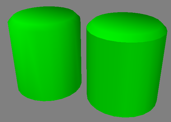
Left: Polygons Not Separated, Right: Polygons Separated
If you wish for your bevel to become a smooth rounded edge that appears to blend into the object instead of the sharp defined edge you get with separating the polygons, add an extra bevel before, and after your bevel (a subtle shift and subtle inset). This will allow LightWave to correctly shade the bevel to appear the smoothly connect with the rest of the geometry.
If you want to create an enclosed solid object when bevelling a 2D polygon, copy it to another layer first and choose Detail > Polygons: Flip. Go back to the original layer and perform the bevel normally. Then, paste the flipped polygon back into the original layer and choose Detail > Polygons: Merge Polys to merge points.
Cut and paste a polygon (like one side of a box) away from its host and bevel it a very small amount. Then, cut and paste the top polygon as well. This makes a nice clean edge that catches specular glints.
When you bevel polygons with sharp edges, you can often run into the problem of points being too close at the corners - very common when you bevel text characters. One solution is to delete unnecessary points near the corners prior to beveling. Don’t be scared to delete too many points; the change is usually so slight that no one will notice, particularly if the text is animated.
Sometimes you also need to manually drag points on the new polygon away from the corner.
Another corner-fixing trick is to bevel out instead of in. This has the benefit of not requiring you to work on any points, but it affects the spacing between characters, if you are working with text. For this, use the Outer setting for Edges in the Bevel numeric panel.