Rail Extrude Tool
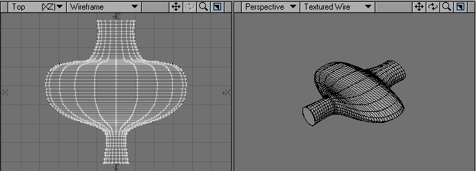
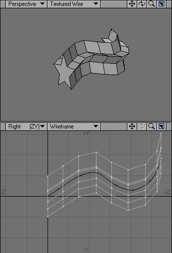
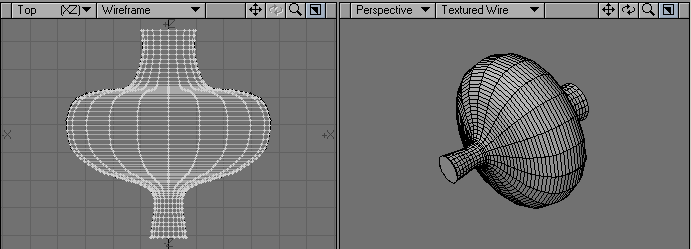
The Rail Extrude command (Multiply > Extend > Rail Extrude) will extrude a point, polygon, or object along a curved path (single rail clone) or multiple paths (multiple rail clone). It is nearly identical to the Rail Clone command, discussed later. The difference is that Rail Extrude forms a continuous skin for the object instead of making individual copies of the object.
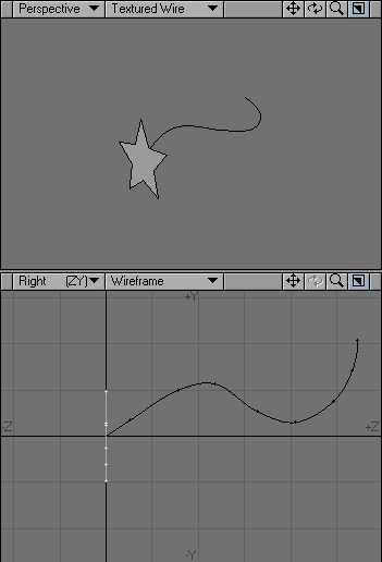
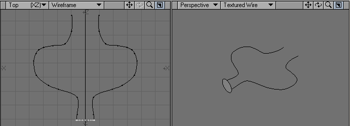
The curve(s) must be in the background layer and the polygons must be extruded in the foreground layer. The orientation and position of the foreground polygons will affect the result.
Generally, they should be at the very beginning of the curve and oriented perpendicular to it - as if the curve was a thread you were threading through the polygons.
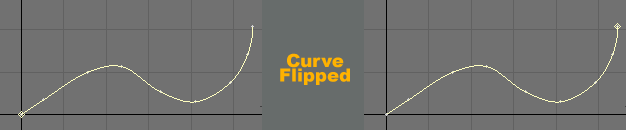
The direction that the curve faces (which end is considered the beginning) will have bearing on both the shape and direction of the cloning. The direction affects the direction of the extruding. If you don’t get the results you expect, try flipping the curve’s starting point with Detail > Flip. If you are using multiple curves, they should generally run in the same direction.
You can use Rail Extrude with multiple layers foreground layers and a single background layer containing the spline(s) and the extruded shapes will be on the same layer as the original polygons.
Single Curve
The Single dialog will appear when a single curve is in the Background layer.
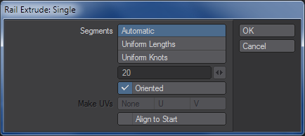
Segments: the number of segments in the resulting object. Select Automatic to distribute a number of segments along the rail curve (based on the Curve Divisions setting on the General Options panel) according to the curve’s knot (point) spacing.
Select Uniform Lengths to distribute some number of segments (which you specify) evenly along the length of the entire curve. No matter what the knot spacing is, the segments will remain evenly spaced.
Select Uniform Knots to distribute some number of segments (which you specify) evenly between the knots that make up the curve. Whether the knots are close together or far apart, there will be the same number of segments between each.
Oriented determines the orientation of the polygon template as it follows the curved path. When active, it causes all segments to angle themselves automatically so that they are aligned with the rail curve as it turns. When inactive, it causes all segments to remain in the same orientation as the template so that they face exactly the same way.
If a UV Texture is selected, the Make UVs options are available. You can create the UV Map perpendicular to the U or V axis. You can have the U or V value assigned to a range from 0 to 1. Note that a UV Texture must be selected or this option will be ghosted.


Multiple Curves
The Multiple dialog will appear when multiple curves are in the background.
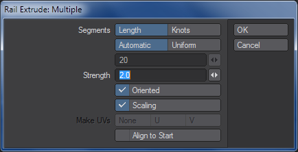
In practice, one curve will act as the main cloning curve and the other(s) act as shaping curves. The effect of the shaping curves is determined by the distance from the main curve. However, you may change the effect by moving the polygons closer or farther away from any of the curves.
Segments is the number of segments in the resulting object. Select Automatic to distribute a number of segments along the rail curve, based on the Curve Divisions setting on the General Options panel. If you also select Knot, segments are distributed with regard to the curve’s knot (point) spacing. If you use Length, knot spacing is disregarded.
To specify the number of segments, choose Uniform and enter the number in the input field. If Length is also active, the segments will remain evenly spaced no matter what the knot spacing is. If you use Knot instead, there will be the same number of segments between each knot, no matter how close together or far apart they are.Strength determines how strongly the rails vie for control of the point locations. You will not notice much of a difference unless you have Scaling deselected. The higher the Strength value, the closer the object will hug the rails.
Oriented determines the orientation of the polygon template as it follows the curved path. When active, it causes all segments to angle themselves automatically so that they are aligned with the rail curve as it turns. When inactive, it causes all segments to remain in the same orientation as the template so that they face exactly the same way.
Scaling determines how segments along an axis are sized. If the rails in the background layer spread apart along any axis or axes, then the segments will automatically stretch along those axes as well. Turn Scaling on to scale segments equally, rather than along those specific axes only.
For example, with Scaling off, if you Rail Extrude a polygon along the Z axis using two rails that spread further apart in the X axis, the segment’s copies will be stretched on the X axis to maintain their relationship to the guide rails.