Fracture
Fracture in Modeler
This new Modeler tool (Multiply tab > Destroy > Fracture) breaks apart an object and makes the resulting segments into parts for use with dynamics. There are three algorithms implemented in the Fracture tool: Voronoi, an algorithmic way of breaking an object in a natural-looking fashion; Halves, a recursive split-in-half algorithm; and Matrix, a matrix-cutting algorithm.
Many aspects of 3D work involve modeling properly for the intended use of the model. For example, many articles and discussions are available on how to model characters in order to be able to animate them properly. The flow of the polygons in the model is critical to getting the correct deformations to occur. There are similar discussions of modeling requirements for other purposes. For the current version of Fracture, you will get better results if you avoid geometry with long thin polygons, or with a disparity in the size of the polygons in the mesh - large polygons mixed with tiny ones.
Lastly, any object to be Fractured needs to be frozen, not sub-patched because Fracturing will destroy the polygon flow needed by subpatches.
Cutting tools need to be fully closed meshes. For example, a cutting tool for Fracture cannot be a cone that you have chopped the top and bottom off of and distorted, so that you have an open mesh with a hole in the middle; you need a closed mesh, with no holes and preferably tripled.
Overview of Controls
Common Settings
- Interior Surface - Entry field to set a name for the interior surfaces created in the fracture process.
- Random Seed - Entry and minislider to adjust the random seed used for the fracturing process.
- Preserve Original toggle - On keeps the unfractured original geometry in the layer it was created. Off does not preserve the original geometry. The undo system in Modeler will not always be able to recover the original geometry, so maintaining the original with this option can be useful if you need to retry the fracturing to get the results you prefer.
- Create in - This offers the choice of either creating a completely new fractured object or creating a new layer for the existing object.
- Part to Layers - LightWave will happily deal with the fractured object being in a single layer, but if you need to export to a different program that needs separate layers you can use this.
Explode Controls
The Explode morph map can be used as a “poor man” dynamics. Just animating the morph to explode a seemingly solid object and adding particles and HyperVoxels can often substitute for expensive dynamics simulations.
- Explode Parts toggle - When checked this makes an exploded Morph map of the parts.
- Explode Distance - Sets the maximum distance for the explosion. This controls how far to move each connected part away from the center of the object.
- Explode Randomness - Specifies a percentage by which to vary the distance. For instance, if distance is 1 m and randomness is 50%, then the pieces will move away from the center anywhere between 0.5 m and 1 m.
- Explode Morph - Name for the exploded morph map.
Morph Maps can be examined using the M icon at the lower right of Modeler’s interface and the dropdown menu that goes with it. This way you can see the morphed object and the base fractured version.
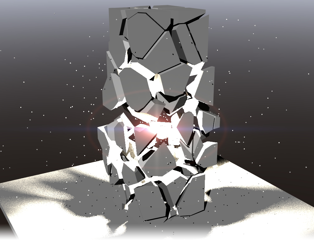
No Dynamics. The morph, some lens flare and particles are enough to make a good background explosion.
Fracturing Algorithms
Voronoi
- Use - There are three choices:
- Random Points - This will create randomly positioned Voronoi cells with which to break up your object based on the value set with the Cell Count field.
- Background Layer Points - A set of points on a separate layer to the geometry you wish to fracture will be used for the basis of the Voronoi cells. The points need to be shown as a background layer, similar to Boolean operations. Points outside the geometry’s bounds will be clamped to the bounds for the cutting operation.
- Background Layer Polys - This is something of a mix between Random and Background Layer Points. To use it, you need to create a closed 3D shape in a layer that you have as the BG layer for the object to be fractured, and the Cell Count field is available to fill that shape with the required number of cells used to fracture the original object.
- Cell Count - This field is ghosted if you are using Point Selection since the number of cells is determined by the quantity of points you use.
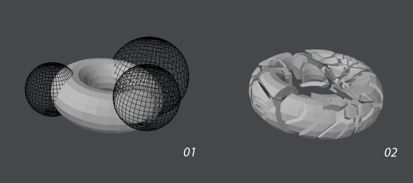
This image shows a Background Layer Points Voronoi fracture. Although the points are not within the bounding box of the mesh to be fractured they still have a pleasing effect.
Background 3D shapes for cutting Voronoi Fractures in Background Layer Polys mode must be closed objects. It is best to triple them and make sure all normals are facing outwards.
Matrix
- Detail - The detail factor controls how many pieces are created. The value entered is exponential (similar to subdivision surfaces) - 1 = 4 parts, 2 = 16, 3 = 64, etc.
- Jitter Amount - Controls how much to jitter the source cutters. Higher values lead to more uneven results.
- Jitter Iterations - Controls the number of times jitter is applied. This is similar to the iterations value in smoothing tools. Higher iterations with low values gives a different result to fewer iterations with high values. The former would move each point around more than the latter, which will move certain points more.
The three images show differing levels of Jitter and Iterations. 1 is no jitter, 2 is a Jitter amount of 50%, but an iteration count of 50, which is high and 3 is a jitter amount of 90% with only three iterations giving a far more jagged appearance.
Halves
- Cutter - This determines the shape of the cutter used to fracture the objects.
- Fractal Cube - Creates more organic results - like a rock being fractured.
- Cube - Makes straight slices - very angular results.
- Max Angle - This sets the maximum angle of rotation of the cutter as it is making slices. If you set it to 0, all slices will be axis-aligned and the results are very cube-like. With a high value, more sharp pieces that aren’t axis-aligned are generated.
- Unevenness - This chooses how uneven the splits are, by percentage. At 0%, everything is split down the middle. At higher values, the algorithm splits more off center. It’s a guide so where it cuts is still random, but with higher values the results will be more random.
The three images above show: 1. Perfectly even cuts, no unevenness and no angle variation, 2. Changed unevenness to cuts that are not exactly halves, 3. Shows adding in an angle variation.