Subpatch Modeling - One
Basic Definition and Terms
Subpatch Modeling (often referred to - technically speaking - as subdivision surfaces) is a process where you create a base shape from a polygon mesh (Base Mesh) then switch to a mode - TAB key - that subdivides these polygons into a rounded smooth organic shape (Subpatch). You can edit the shape in subpatch mode or you can switch back and forth using the TAB key. Some modelers prefer to do most of the editing in polygon mode whereas others prefer the organic feel of subpatch mode. More on this later. If you are new to subpatch modeling or to subdivision surfaces in general or even new to 3D you might want to take a look at this article for more information on the many uses for SDS before continuing with this tutorial.

Subpatch and Catmull Clark
As of LightWave 9.0, Modeler has two modes of subdivision surfaces. Subpatch mode, the mode we have had since Modeler got subdivision surfaces and Catmull Clark, (new to 9.0) named after the two men who invented it. In Subpatch mode you are restricted to using polygons of three or four sides.
There are two differences in Catmull Clark (or CC) and Subpatch. One is that CC can use polygons with more than 4 sides called Ngons. The other is in the math that CC uses to subdivide the surface in Layout and in the display of Modeler.
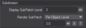
This is important to know. In Modeler, you set the subdivision level for both CC and Subpatch by bringing up the General Options panel. The Shortcut is "o" on the keyboard.

The more geometry you have in your object, the slower it is going to get in Open GL (OGL) when spinning it in perspective view. It is a good idea to get to know the math of how LightWave subdivides the base mesh both for your Modeler display and for rendering in Layout. This affects how your model will look in Modeler and how it will display and render in Layout. They are basically the same except that Layout then displays and renders in triangles which doubles the poly count from what you are "seeing" in Modeler, say in shaded solid view.
In Layout you set the level in the Geometry Tab of the Object Properties Panel - press "p" with the object selected - one for display and one for render.
Subdivision Math
Here is the math in very simple practical terms:
In layout:
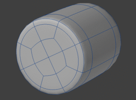
(Sample is 1 square polygon)
Subpatch
| Level 1 | |
|---|---|
 | This subdivides each polygon with one polygon. That is, it is a 1x1 subdivision = 1 polygon. Then each polygon is converted into tris making 2 polygons. (The one polygon cut at a diagonal) So level 1 = 2 polygons. |
| Level 2 | |
 | This is 2x2 subdivision = 4 polygons That's basically a row of 2 polygons down the X and a row of 2 polys up the Y. Now these polys are divided diagonally to make tris = 8 polygons. So level 2 = 8 polygons. |
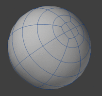
| Level 3 | |
 | This is 3x3 subdivision = 9 polys made into tris (doubled) = 18 polys. |
| Level 4 | |
 | This is 4x4 = 16 polygons, tris = 32 and so on. |
Catmull Clark
| Level 1 | |
|---|---|
 | Level one takes the original polygon (1) and doubles this number to come up with the number for an equation. So it is so it is 1 polygon - our sample times itself so that we get 2. This number is then inserted into the equation (a)x(a) to get 2x2 = 4 polys divided into tris to make 8 total polys |
| Level 2 | |
 | Takes the number created by level 1 (2) and doubles it and uses this number (4) in the equation. So it is 4x4 = 16 doubled by making it into tris = 32 Numbers sounding familiar? Just like binary code for computer data and computation - well, no need to go into that. |
| Level 3 | |
 | This takes the number from level 2 (4) and doubles that ans uses it in the equation. So it is 8x8 to get 64 subdivided into tris to get 128. |
| Level 4 | |
 | This is 16x16 = 256 and made into tris = 512 polys |
Summary
- Level 4 Subpatch - 32 polys
- Level 4 CC - 512 polys
So as you can see there is quite a difference. If you are going to use CC, know that you should set it to a low display level in Modeler and in Layout otherwise it will bog down and be too slow to work. You can also use this math to predict how many polygons LightWave will render. With larger scenes this will be crucial to know as it will make a big difference on ram usage.
More Terms
Let's go over some more terms.
- Quadrangle - A quadrangle is a polygon that has four sides. This is often referred to as a Quad. These two subpatched primitive shapes consist of all quads.
- Triangle - Here we mean a polygon that has three sides. This is often referred to as a Tri.
- Ngon - An Ngon is a polygon with more than 4 sides or points.
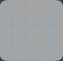
- Grid Mesh - A grid mesh is basically just that, a simple cross hatch of polygons.
I use this term to indicate areas of the model that act as a connecting web between areas of particular detail.
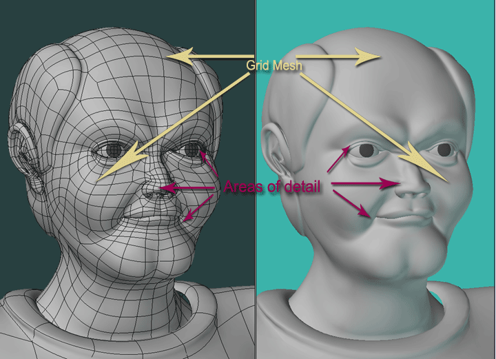
- Edge Loop - Areas of detail and contour are defined by Edge Loops. These are a series of quads that form a complete or partial loop and thus change direction from the grid mesh.
- Poly Flow - Poly Flow is a term that is often used to indicate the overall design and structure of a model using grid mesh and edge loops. The poly flow for a head, as an example, could be plotted out in predictable areas where detail will be added such as the eyes and mouth.
- Points - You should already know what a point is. But in subpatch we look at a point as a vertex. That is to say, connecting points where more than one edge merge and this is indicated by how many polygons share that point. This is a very important concept for subpatch modeling. I have also seen this referred to as a Star or a Pole. Regardless of what you call it, the main thing is - how many polygons does that point connect to?
Rules
Hard Rules
Let's take a look at the basic rules that apply to subpatch modeling - technically speaking. That is, the rules that you can not bend.
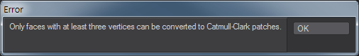
Subpatch - You must have polygons with at least 3 but no more than 4 points.
If not, when you hit TAB, you will get an error message:
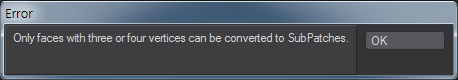
And the polygons that are illegal will not subdivide.
Catmull Clark - You can have polys with more than 4 points called Ngons but the minimum is still a polygon with 3 points.
If not, when you hit TAB, you will get also an error message:
And the polygons that are illegal - in this case a 2 point poly - will not subdivide.

Soft Rules
From these guidelines or restrictions we arrive at a set of soft rules - if you will - that come from application and observation. Some of them based on artifacts that you may encounter while trying to render your image, others based on experience in getting predictable shapes with economic use of polygons. We will cover the soft rules in this tutorial. And I should note that even though you can have Ngons in a Catmull Clark subdivision, most of the rules that come from working with a maximum of 4 points still apply and it should be assumed unless specifically noted that we are in standard subpatch mode throughout this tutorial and not Catmull Clark.
Basic Theory and Concepts
Overview
Generally speaking creating a subpatch model is a process of connecting areas of detail defined by edge loops to greater areas of the model that form the general shape or form of the object and giving yourself ideal points to edit the shape smoothly and predictably. The more complex the object, the more complicated this process becomes.
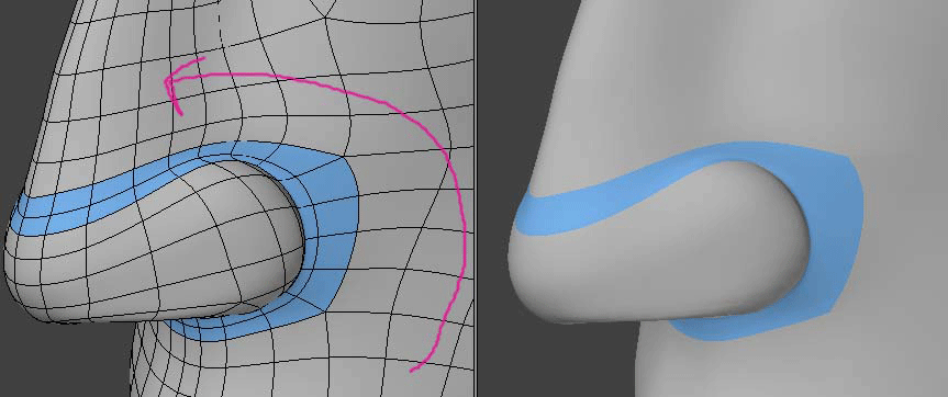
Here is a simple illustration.

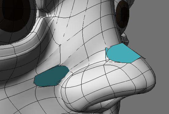
Giving yourself an editable edge
In this illustration you see that an edge loop is defining the shape that protrudes from a flat surface.
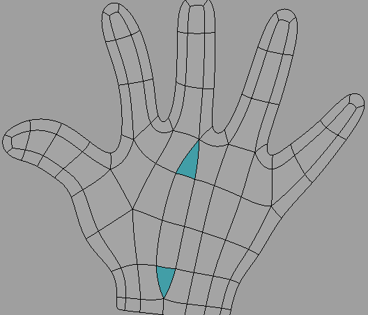
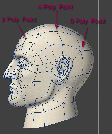
Notice that where the edge loop connects to the outer mesh there are 5 poly points and where it connects to the inner mesh there are 3 poly points.
In between these two areas is an edge loop that is made up of 4 poly points. This is indicated as an "Editable Edge".
Both the 3 poly point and the 5 poly point are difficult to edit predictably and will often cause unwanted bumps in your model. Points with 6 or more polys connected will give you a pinching effect and in general be difficult to get placed properly.
An ideal editable edge, or point for that matter, is one that is connected to 4 polygons. No more and no less. This will give you smooth predictable results.
Triangles
Triangles also come into the avoid category. They are sometimes unavoidable. They should be placed in an area that is nearly flat or that will not be visible such as behind an ear. They can also cause smoothing errors in a render.
Keep a simple low poly count
An ideal object has only the polygons needed to create the shape and no more.
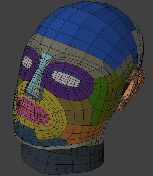
Balancing extremes
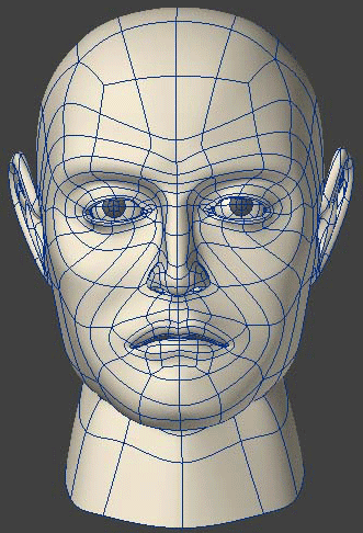
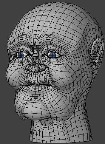
These two heads illustrate a low poly example and a high poly example.
The advantage of the high poly example is that there are more options to edit the shape. This particular example was taken from a base head then molded into this character (more on this method later). The disadvantage of course is the mesh is too dense and can create a slow down of layout during animation and takes up more ram.
The advantage of the low poly head is that is is faster to animate and takes up less ram. The disadvantage is that changing the characteristics of it as well as morphing it will not be as easy or smooth.
You have to balance these extremes because in order to have the ideal editable mesh and avoid 5 and 6 poly points as well as triangles, it takes more geometry. 5 poly points of course are unavoidable. But as you begin cutting back on this you have to add more geometry.
Stepping down
Stepping down is the process of taking your high detail areas and reducing the polys so that the over all mesh area is less dense. And again in doing so you create more 5 poly points and, depending on your method, perhaps triangles.


The above pictures illustrate the basic concept and sequence of stepping a mesh down so that it goes from high density to low density. An area of high detail to one of low detail. Stepping down is one way to balance these extremes and have a model that has enough detail where needed and is not too dense to be practical. Notice how it creates points and edges that will be difficult to edit. These should be placed in an area where they will not be defining contour or detail, but rather, on flat or slightly curved areas of the model.

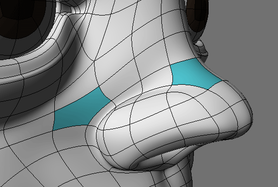
Here is one practical example. The detail of a hand stepped down to the lesser detail of an arm starting at the knuckles where bumps are expected.
Separate Parts
This simple concept should not be overlooked. A subpatch model does not always have to be one part. A great example is creating an eye socket as part of the head and inserting an eyeball. This is not only good for animating the eyes it also makes good practical sense in creating the object. Not all parts have to be connected. An arm can disappear into a shirt. A handle can rest against a mug cylinder, a side view mirror against a car body, separate pieces of a chair or other furniture, as just a few examples. By separating things into parts you can eliminate the need to graduate from high detail to low detail. Deciding what can be connected and separate is a vital step in planning how to model an object.
To Boolean or Not to Boolean?
Modeling has gone though many advancements in technology over the years. One of the very early advancements was the ability to use shapes to cut out other shapes. Many modelers still use this technique. When spline patching, then smooth subdivision (Metaform) and eventually subpatch modeling came along, modelers turned away from Boolean operations in favor of newer more efficient ways of modeling. Furthermore, Booleans can be sloppy. Poor planning and misuse has lead to many modelers to have the opinion that Booleans "make hash" of your mesh, are difficult as well as time consuming to clean up and in general are not reliable. For this reason Booleans have become rather taboo in subpatch modeling. To be clear, a Boolean won't work if you have subpatches turned on. However, used properly and with good planning, Booleans are a very valuable tool for preparing a polygon base mesh for subpatch - especially in creating inorganic objects. There are certain things you will need to know to make Booleans and stencils work, and I will go into these techniques as we get into creating some shapes.