Virtual Studio
About Virtual Studio
Virtual Production workflows are changing the face of CG and live action production, visualizations, and design. Most individuals and small to mid-sized studios assume that virtual production technology is out of reach but the truth is that this technology is scalable and very flexible. With LightWave and its Virtual Studio you can perform virtual location scouts of a 3D set, record handheld camera moves on a fully 3D LightWave scene, use game controllers like the PS3 Move controllers to drive character animation, and control lights all in real time. In fact, any channel that can be animated in LightWave can be controlled with Virtual Studio. Clients love this type of interaction for meetings and virtual walk-throughs and it is easily within your reach with LightWave Virtual Studio.
LightWave’s development team are bridging the gap between real and virtual worlds. Our real world interface with LightWave has been fairly constant for years using a 2D screen output, a keyboard, and a mouse pointer with some buttons. These days, there are more real world devices we can tap into to allow real world humans to interact with LightWave. These include: motion tracking devices, 3D mice, gesturing, accelerometers, virtual buttons, wireless displays, joysticks, cameras and more. With Virtual Studio, LightWave can support many of the capabilities of a real studio, such as recording and adjusting live action, the key being ‘live’ action. Animators have always had the ability to adjust motion in an animation at a fundamental level (key frames) but producing the most realistic looking motion requires capturing real world data or simulating it procedurally. The purpose of LightWave’s Virtual Studio is to work with real world data by bridging the gap between LightWave and a real world studio.
Overview of Controls
Before we go into specifics, here is a presentation of the three principal windows Virtual Studio uses in Layout. These can all be found in the Virtual Studio tool group in the Top Menu section of Layout’s menus. The button beneath this group labeled Studio LIVE is a toggle that replicates the LIVE! button inside the Studio window for ease of access. This button creates a live-feedback evaluation of the scene (and its traits) that updates viewports to see the feedback. Without Live!, scene evaluations only occur when the scene time changes and in a few other situations, but not at a consistent frame rate like with Live! enabled.
The Device Manager
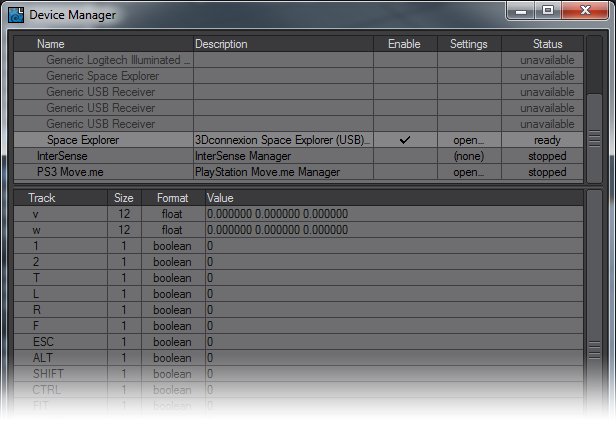
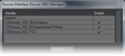
This assigns your connected device to be used for the Virtual Studio. You need to click the Enable column for the device type, this will be either a HID (Human Interface Device) compatible peripheral, the Intersense VCam or the PlayStation 3 Move controller. If there are devices you don’t own, or are never likely to, you can remove them from display to make it tidier. Right click on the manager entries you wish to remove.
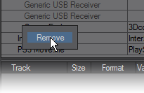
If you plug in a device of the type you have removed, you will get the entry back in Device Manager.
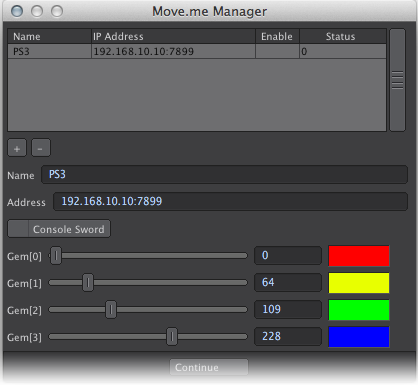
Once you have enabled your specific device, you can click on the device’s name to see the readout of LightWave-supported Tracks. In the case of PlayStation 3 Move.Me controllers you can adjust the gem hues at the top of each Move controller. The gem color settings in this panel are just used as a guide for Move.Me to change the gem colors (they won’t necessarily be exactly the same as on this panel) and colors that are too similar will not be allowed. The Console Sword button changes the onscreen appearance of the Move controller to the sword object assigned to the gem on the PS3.
The generic version of a HID device is purely the HID manager version. The generic device is limited in functionality, usually just to button presses; elements like accelerometers need to be specifically programmed. If you need to choose between devices always choose the non-generic version that has been specifically programmed for LightWave. Going further, you can remove them from view with the HID Manager Settings window.
The Control Booth
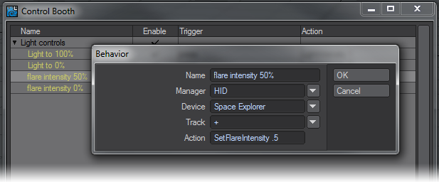
This is where you set up behaviors using Layout commands to drive functionality for your device. The control booth is a way to control Layout similar to how one would assign keyboard shortcuts to do things that the user would normally use the GUI to do. These behaviors are not part of the scene. The control booth is a user interface tool. To know what commands are available go to the Utilities tab and click Save CMD List. The Space Explorer in this example has fifteen buttons in addition to the central controller and these can be assigned actions in the Control Booth. These settings are saved into a config file in your user directory: %USERPROFILE%\.NewTek\LightWave\2019\configs\ControlBooth.cfg on Windows systems, and under OS X: ~/Library/Application Support/NewTek/LightWave/2019/configs/ControlBooth.cfg
You can import or export collections of commands by clicking on the + symbol at the bottom left corner of the window.
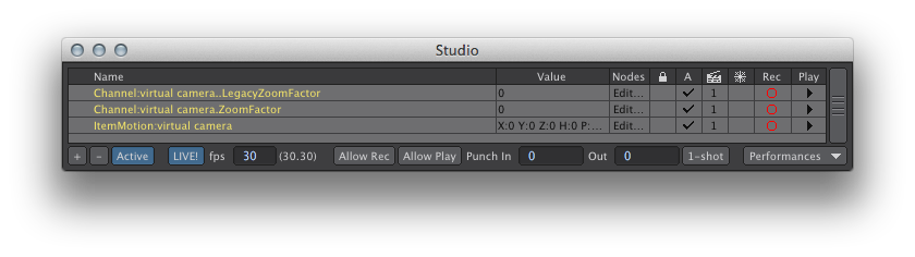
The Studio
This is where you will record your performances using the devices you set up in the Device Manager, using the behaviors you set up in the Control Booth — although the Virtual Studio can be driven without a third party peripheral. You can have an unlimited number of Performances recorded for a device to choose between for incorporation into your scene’s timeline.
Listed in this window are the traits that will be recorded with the Virtual Studio.
- Name - the name of the item. Double clicking on the name will open the node graph showing the connections needed for setting it up. Alternatively you can single click on Edit... in the Nodes column.
- Value - is the readout of the current output from the trait.
- Nodes - Click on the entry in this column to edit a trait’s node network.
- Padlock - Allows the user to lock all the settings for the item (or group) so that no changes can be accidentally made without first clicking the padlock again.
- A - For active. This determines whether the virtual studio will be looking at output from the trait.
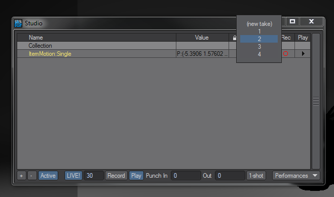
- Clapper board - The take number you are on. You can click on this number to change the take, or to add a new one.
- Snowflake - Freeze. This icons stops all evaluation from the item.
- Rec - This arms the device for recording. This is an individual record function so that you control which traits are to be recorded.
- Play - This arms the specific channel for playback. Like record, it’s an individual function.
By default, when you bring a new trait into this window the Rec and Play columns are armed.
At the bottom of the window there are more functions:
- ‘+’ Clicking this button brings up a submenu:
- New Empty Collection - Allows you to create a new group for assembling your traits.
- New Collection Of Selection - If you have a series of traits selected in the Studio window, this will put them all in a new collection. Collections are renamed by double clicking on them.
- New Take - This will set up a new take for the selected trait.
- ‘-’ Will bring up a submenu:
- Remove Active Take of Selection - Removes the current take.
- Reset Active Take of Selection - Zeroes out the take, but doesn’t remove it.
- Remove All Takes of Selection - Deletes all takes from the selected Studio trait.
- Remove Selected Collections - Removes the selected collections.
- Active - A global button to evaluate Studio functions.
- LIVE! - Live is the live-feedback evaluation of the scene (and its traits) that updates viewports to see the feedback. Without Live!, scene evaluations only occur when the scene time changes and in a few other situations, but not at a consistent frame rate like with Live! enabled.
- FPS field - This requests a frames per second rate for the whole scene when used through the Virtual Studio. The following number is the actual reported FPS, useful for complex scenes that might not be able to play back at the requested rate.
- Allow Rec - This is the Global record button. It allows the individual Rec settings.
- Allow Play - This is the Global Playback button. It allows the individual Play settings.
- Punch In/Out - used if you only want to use the Virtual Studio for a section of the scene. Left at 0 it will record the whole scene.
- 1-shot - this records the motion of your traits during a single playback of your scene, when it reaches the end of the timeline recording stops. This also works if you are playing back in reverse to reverse-record your traits at which point it will automatically stop when the timeline reaches the beginning of the timeline.
- Performances - this opens a sub-menu related to storing multiple performances. Performances are useful for more complex setups where there are multiple scene assets being affected. A use case may be giving a director multiple options to choose from; but instead of being able to change just one take to accomplish that, it may require a lot of settings changes. The performance would encapsulate all the setting changes (to traits only) for quick switching. Another example could be a single ‘actor’ performing multiple roles in the scene: camera man, lighting, driving a car, effecting explosions where the car drives. A performance could be setup for each so that the real person can switch roles quickly and record or playback only the parts needed.
Studio Assets Submenu
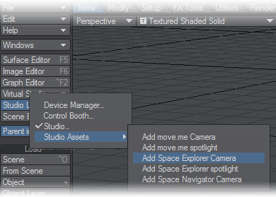
Rather than needing to use Load from Scene to bring in a camera or light from a scene where they have been set up, the user can simply choose the appropriate command from the menu to add a camera or spotlight. Examples have been put in this menu for PlayStation 3 Move.Me devices and 3Dconnexion Space Navigator, Explorer and Pilot Pro devices.
Users can add their own devices to this submenu by editing the Python scripts and providing an identically-named scene. Look in LightWave/Support/Plugins/Scripts/Python/Layout/Virtual Studio directory to see the examples. Once done, the new scripts need to be added using the Edit Plugins window or by restarting LightWave if you use Autoscan Plugins, and then the plugin needs to be added to the Assets menu using Edit Menus.
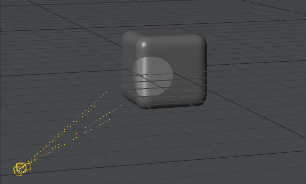
 Example: Car Shoot
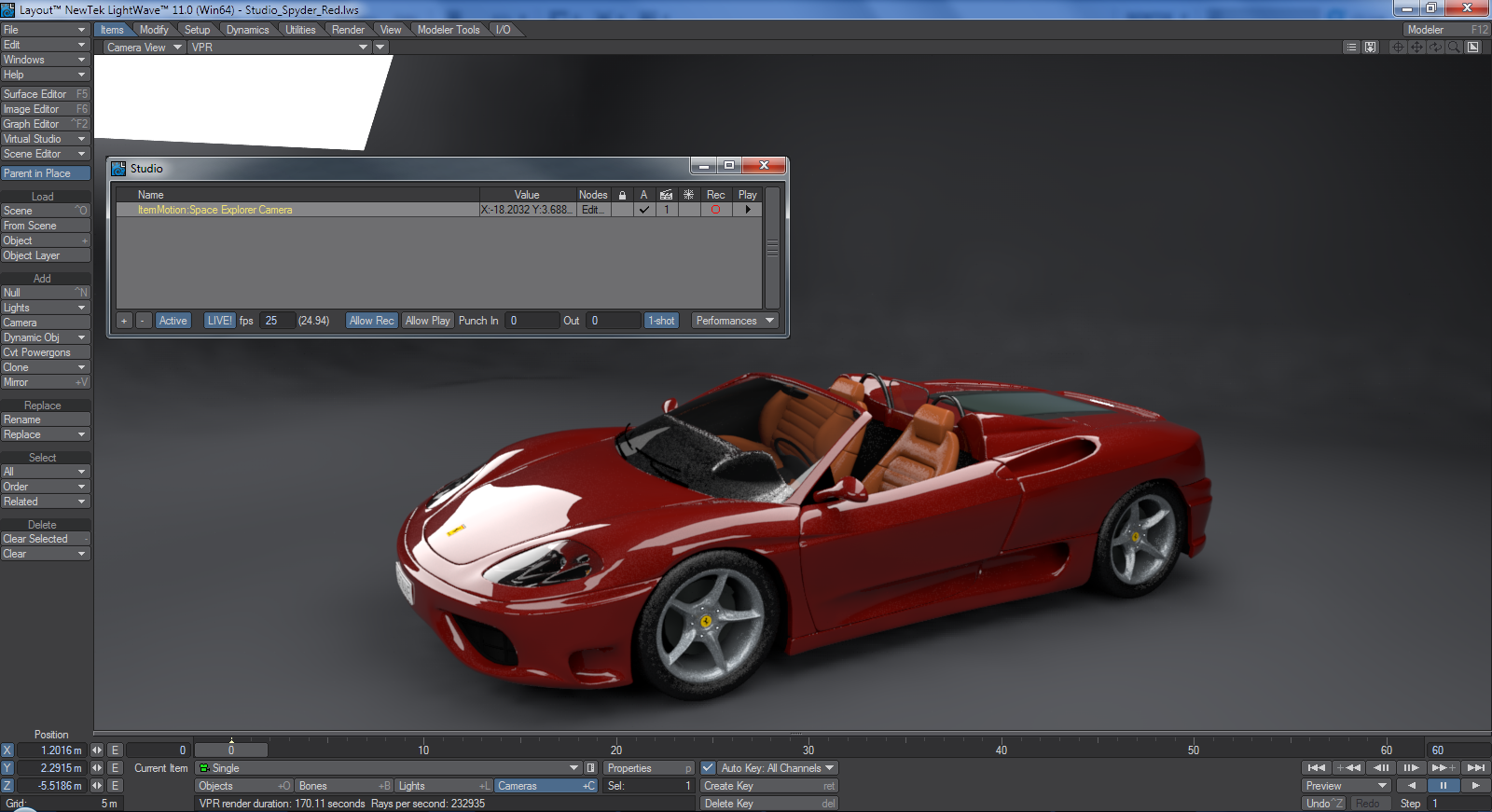
Note that to get VPR to resolve you need to turn off the LIVE! function so that the Virtual Studio isn’t constantly evaluating your 3D device.
The director wants to shoot a turntable of a new car and wants to direct you in the motions you will use. We’re using the Studio_Spyder scene from the content for this example. Use the Virtual Studio > Studio Assets menu to add a camera for the Space Explorer, Space Navigator or PlayStation 3 move.me system to the scene. If you wish to build your own node network to control the camera, individual nodes are explained starting on page PDF_LINK; the 3Dconnexion setup used for this example is explained starting on page PDF_LINK of the manual and a move.me node explanation can be found starting on page PDF_LINK
Before anything else, make sure your Nav tab in Options is set to Device: (none)! You don’t want to make Layout use the same device for two different purposes.
A Space Explorer was used for the purposes of this scene. If you have a 3Dconnexion device not listed in the Studio Assets menu, you will need to double click on the trait item in the Studio window and open the Device node to associate your 3Dconnexion device with the node network.
Once you have your new camera in the scene you will see that it is positioned badly so you need to give it a better starting position using your 3Dconnexion device, if it doesn’t move, make sure Live! is ticked in the Studio window or in the Top menu group of Layout. Now we can start.
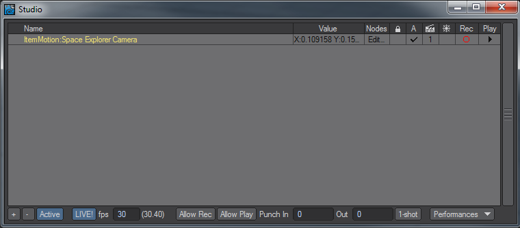
- You need to make sure you have Active , Live! , Allow Rec and 1-shot all checked in the Studio window. Up on the trait for the Item Motion: Single you want the Rec and Play buttons checked too. You should be on Take 1. The scene only has 60 frames so it’s going to be quick, but that’s okay for this test. You need to be comfortable with using the 3Dconnexion device to control the camera smoothly and accurately and you can always change the playback rate of your scene if necessary.
- When ready, press play on the scene and be ready to move your 3D mouse to capture the changes in position you want.
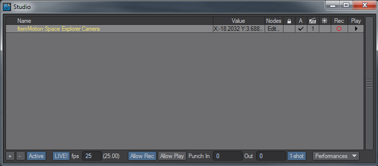
- When the scene is done playing the Allow Rec button will switch off. Click the Allow Play button in the Studio window and play your scene back. You will see the motion you recorded. If you’re not happy with it, you can always hit the Allow Rec and 1-shot buttons again and redo the take. If however, you’d like to keep this take and try another, click in the Studio window in the clapperboard column. You will be presented with the possibility to choose between your takes or create a new one.
- Your takes can be chosen between and played back on the timeline and when you are happy to render make sure the Studio Allow Play button is active for the take you want to render. All your takes are saved into your scene file.
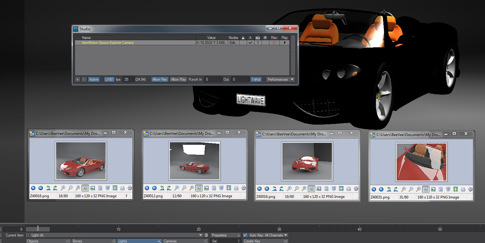
All four takes were rendered and saved into a single scene.
3Dconnexion Example Setup
The node network for the 3Dconnexion example shown at the start of this section looks like this:
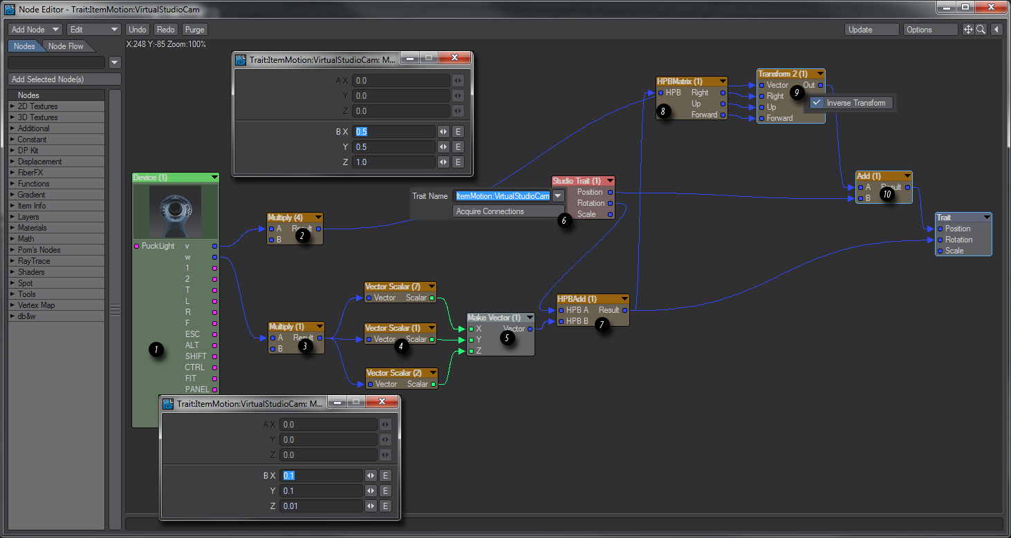
This is how the individual nodes work:
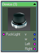
- This is our Device node. Here we are using a 3Dconnexion Space Explorer. If you are using a different model you will have different outputs, but the main ones devoted to movement are the same for all models - v for Position and w for Rotation.
- This Multiply node allows you to scale the sensitivity of the movement controls of your 3Dconnexion puck. The settings are shown in the window above.
- This Multiply node allows you to scale the sensitivity of the rotation controls of your 3Dconnexion puck. The settings are shown in the window below.
- These three Vector Scalar nodes allow you to change the axis order to match the device’s rotation to the Euler angles LightWave uses (Heading/Pitch/Bank). Here Y goes to X, X goes to Y and Z is passed through.
- The three Scalar outputs from 4 go into a Make Vector node.
- The all-important Studio Trait node. This links a scene item (in this case VirtualStudioCam) with your node network and thus your device. The Position goes straight to the Add node in item 10 and the Rotation to item 7.
- The HPBAdd node combines the two rotations of your controlling device and your scene item. The result is sent to the destination Trait node.
- The HPBMatrix node converts heading/pitch/bank Euler angles to a 3x3 matrix output as right/up/forward vectors.
- These outputs are taken, along with the original scaled output from the Device’s v output, and an inverse transform is applied. This is to make the right/up/forward vectors be relative to the Studio Trait node’s orientation (in order to better visualise this, imagine an arrow pointing northeast. What this node does is translate a forward push on the 3Dconnexion device’s puck into forward motion for the arrow, that is to say in a northeasterly direction, not just north).
- The Studio Trait Position and transformed Device v are Added. The result is sent to the destination Trait node.
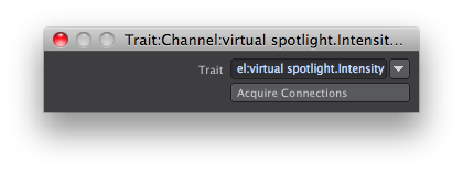
- The destination Trait node.
Virtual Studio Nodes
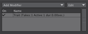
In order to set up a virtual studio scene and be able to use peripherals such as the 3Dconnexion “mice” a series of nodes have been added to LightWave’s Node Editor. They are accessed by adding a Virtual Studio Trait motion modifier to your scene item like so:
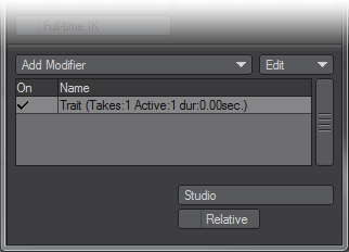
and then double-clicking its entry in the Virtual Studio window.
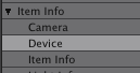
Item Info > Trait - A trait is a motion modifier added to a scene item making it visible to the Virtual Studio. Once you have added this modifier to your scene item, the scene item will become available in the Trait node in the node editor.
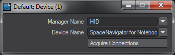
Item Info > Device - A device is the tool you are using to control the Virtual Studio, whether it be a 3Dconnexion peripheral like the Space Navigator or Explorer; a PlayStation 3 Move controller or an Intersense VCam. The outputs for a specific device will be appropriate to that device. The Space Navigator for notebooks here shown has just four outputs for movement, rotation and the two buttons present, whereas the Space Explorer has a total of 15 outputs representing the different buttons on the device.
When you add a device to your nodal network, you need to double click the node to present the following window where you will choose the device you wish to use.
If you set up a scene with a 3Dconnexion Space Explorer or similar with additional buttons and configured nodes relating to those buttons; then use a Space Navigator with no additional buttons the connections for the missing buttons will be lost if you save the scene. The nodes will still be there, but the connections will have to be remade when you reconnect a more fully-featured 3Dconnexion device.
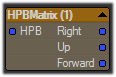
Math > Vector > HPBMatrix - convert Euler angles (heading/pitch/bank) to a 3x3 matrix output as right/up/forward vectors (each being a nodal vector type).
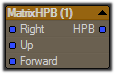
Math > Vector > MatrixHPB - convert a 3x3 matrix (specified as right/up/forward vectors) to a vector of Euler angles (heading/pitch/bank).
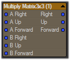
Math > Vector > Multiply Matrix 3x3 - multiply two 3x3 matrices. For rotation matrices, this has the effect of combining rotations. The output is another 3x3 matrix represented as right/up/forward vectors.
![]()
Math > Vector > Transpose Matrix 3x3 - a rotation represented as a 3x3 matrix can be transposed which has the effect of inverting it meaning the rotation is reversed.
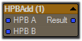
Math > Vector > HPBAdd - combine two rotations represented as Euler angles and output the resulting rotation as Euler angles.
Move.me Example Setup
This is a PlayStation3 application that uses up to four PS3 Motion controllers and the PS3 Eye camera to track the position and rotation of each controller and sends that data across a network to client. That client, in this case, is the LightWave move.me device manager. Once accessible to the LightWave device manager, the data can be used to control your scene elements and user interface.
PlayStation3 Setup
- You must have the necessary hardware and physically set it up. Please refer to your PS3 console for specific setup instructions such as linking the controllers to your system.
- PlayStation3 console
- PS3 Eye camera
- PS3 Motion Controller (up to four; this example specifies two)
- Network connectivity to a LightWave11 system
- You must also acquire the PS3 move.me software application. This is available via the PlayStation Network Store (availability in certain markets may be limited).
- Start the move.me application and get past its instructional splash screens. The screen should display what the camera is seeing, and the upper left corner of the screen will show the console’s IP address with a port of 7899. This is the server that LightWave11 will need to refer to shortly.
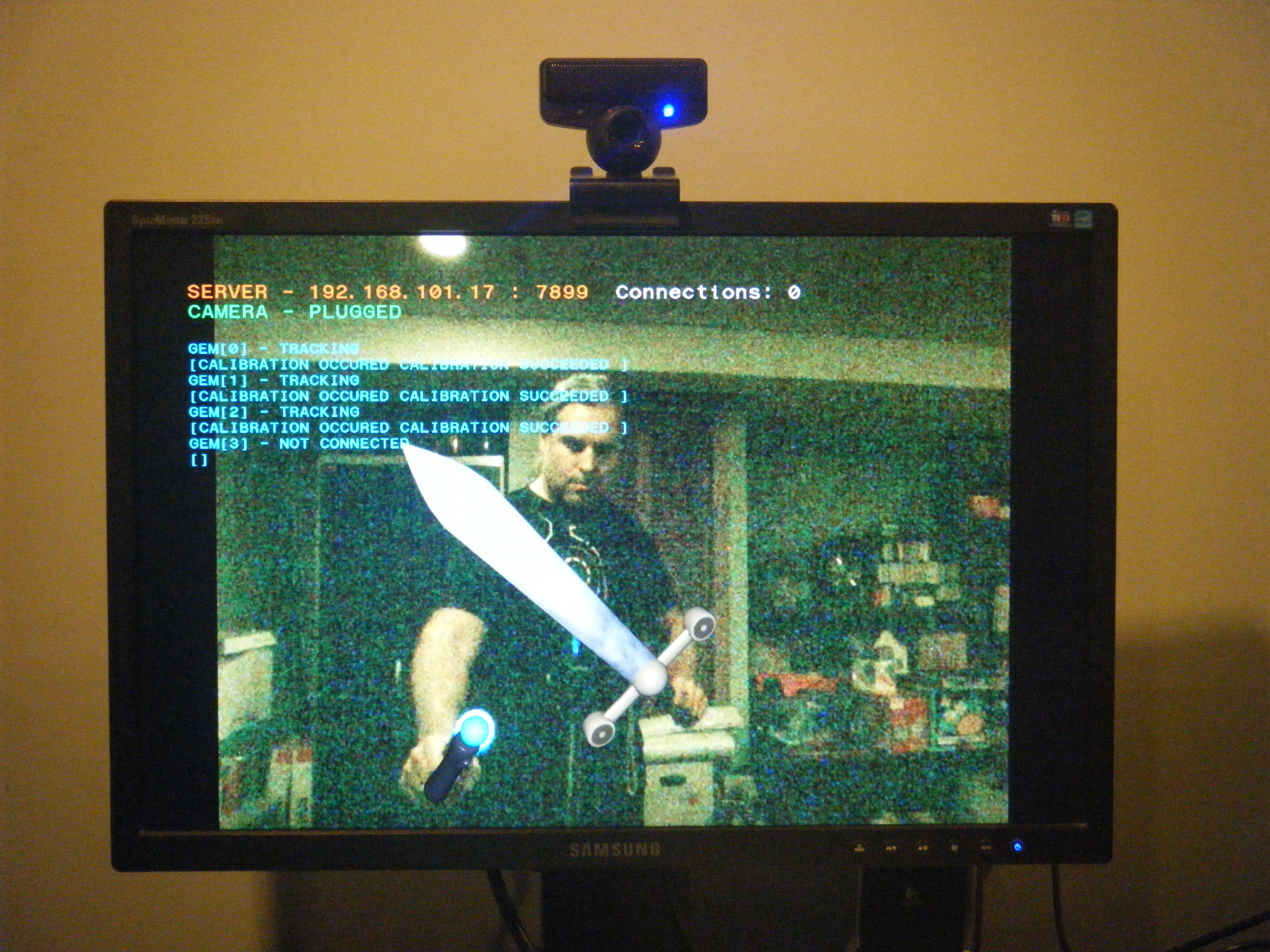
- Repeat this next step for each PS3 Motion controller (also referred to as “gem”). At about three feet from the camera (PS3 Eye), point the Motion controller directly at and inline with the center of the camera lens, remain stationary, and press the Motion controller “Move” button (the largest top-side button). The gem will flash and finally settle-in on a color (Each gem will have a unique color.) You must be fairly still until the final color is visible; this is a calibration procedure. After the calibration, do not rotate the camera as that will disrupt the orientation calibration. As the controller is moved, you will see a sword (or other avatar) represented on the screen. To disconnect the gem, press the ‘SELECT’ button on its left side. This does not power off the gem, it only disconnects it from motion tracking in the Move.me application. You may then repeat the calibration as needed. It is important to note that gems can only be connected or disconnected when no clients are connected to the Move.me application. After about 10 minutes of non-use, a gem may disconnect automatically (the gem color will go out). If any clients are connected at that time, they must be disconnected before the gem can be reconnected. This behavior may change in the future.
LightWave Device Manager Setup
The device manager in LightWave is the central place to decide what devices can participate with the studio and control booth features. The studio allows devices to affect your scene while the control booth allows devices to affect your user interface, which can also affect your scene. To be more clear, the studio feeds device data into your scene through its natural evaluation process similar to motion plugin evaluation, and the Control Booth interprets device data to issue Layout commands like those that can be entered by a user in the command input and command history panels.
- Open the device manager panel. A table of existing managers is shown
- Find the manager called “PS3 Move.me” and enable it.
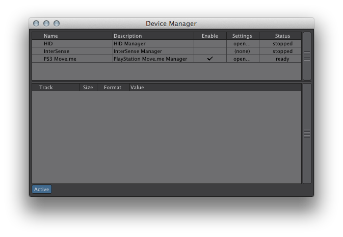
- Open the settings for it.
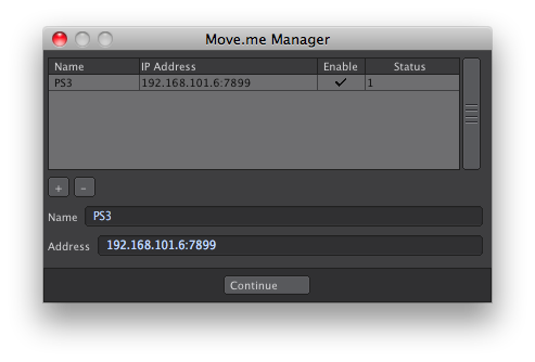
- Click on the “+” button to add an address entry. The default of “192.168.x.x:7899” should appear.
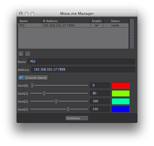
- Look back at the console screen upper-left corner and change the IP address in the Move.me Manager settings to it. The address format is IP:port, so make sure there is a colon separating the IP address and the port value.
- Enable the address entry. If all is well, the status should show “1”. It is important that the “PS3 Move.me” entry on the device manager panel is enabled before attempting to enable an address entry. You can now close this settings panel.
 The “PS3 Move.me” manager should now have four devices (gems).
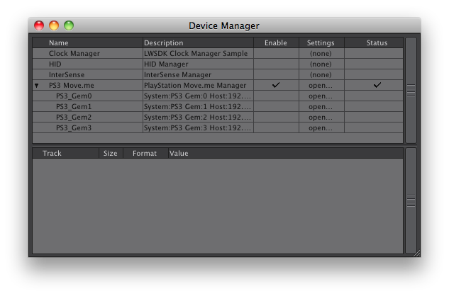
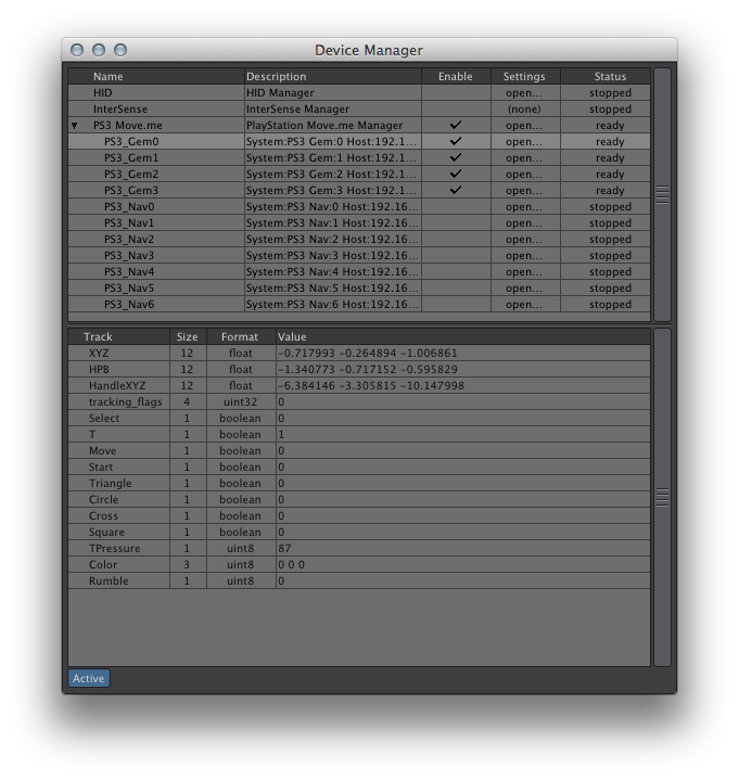
- 7) A device must be enabled for its data to be received; so enable the devices of interest in the device manager panel. Highlight a device to see its data in the tracks table below and confirm its operation by watching the data change as you manipulate the gem.
- At this point, the gem devices are available to studio and control booth.
More than one PS3 console may be connected simultaneously therefore allowing more than four gems in LightWave11.
IMPORTANT! Windows firewall rules may be preventing the data stream even though the setup appears correct. A quick way to troubleshoot this is to disable the Windows firewall for the network connection that the console is on and re-check for track data changes. For a direct network connection between the LightWave11 system and the PS3 console, there is less risk in disabling the firewall; but when the connection is also to the internet, special firewall rules may be necessary. The Mac platform does not have this issue.
The name of a device is its identity when used through LightWave and it should be unique from other devices. Because this name will change depending on how the hardware is setup and what hardware is available, it makes sense to rename devices to something you will use in your scenes and on your system. That way, a simple name change in the device manager will keep away the need to change all scene references to a device. Device names can be changed by double-clicking on its name. The device name and active state are remembered the next time you start Layout as well.
Scene SetupThe scene can be as simple or complex as you like. With up to four gems per PS3 console, you have a lot of options. This example sets up a virtual camera and a virtual spotlight as well as some control booth behaviors.
Take recording requires mapping device data to your scene elements; this is the purpose of studio traits. Control booth behaviors are not recorded in a take.
Virtual Camera Motion
The virtual camera motion will be directly tied to the gem motion.
- Create a scene camera and name it “virtual camera”.
- Open the motion properties for it, and add the Virtual Studio Trait modifer. This will add a new trait to the Studio.
- If the studio panel is not already open, you may open it in either of two ways: a) Open the properties for the plugin and click on the Studio button, b) choose the studio menu option (provided your menu configuration has it available).
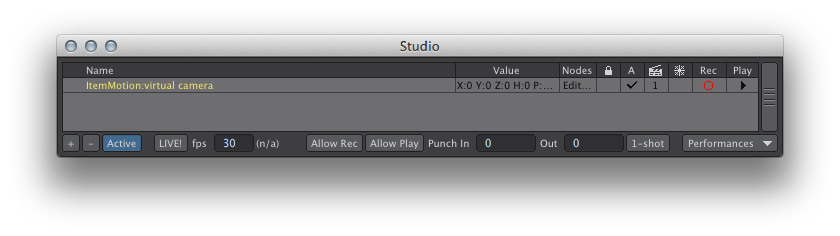
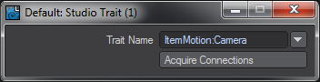
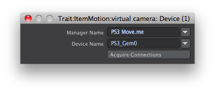
- Edit the node graph for this new trait. In the studio panel, locate the trait named ItemMotion:virtual camera and double-click its name or click Edit in the Nodes column. This opens a node graph with a target node representing the trait’s position, rotation, and scale.
- Add a device node from the Item Info category to the node graph.
- Open the properties for the device node, and set the manager and device to PS3 Move.me and PS3_Gem0 respectively.
If the devices are available in the device manager window, they can be selected via the drop-down gadgets in the panel. Otherwise, you may simply enter the names directly; however, no understanding of them will be available to complete the node graph. You may continue on with the node graph and make the final connections once the required devices are available. Once the node graph connections are made, they will be remembered when reloading your scene even if the devices are no longer available.
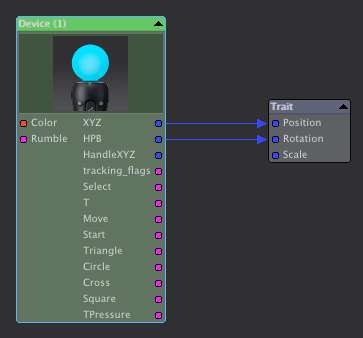
- Connect the device node XYZ and HPB to the trait Position and Rotation respectively;
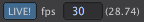
- In the Studio panel, enable the LIVE! button and make sure the value to its right is reasonable for your system (suggested 10 to 30). This value is a evaluation update rate. It determines how many times per second the scene is evaluated and redisplayed in the view ports. This allows you to see scene changes as a result of gem movement even though the scene time is not changing. Once this is done, you should now see the virtual camera moving in your scene as you move your gem.
The PS3 Eye must be able to see your gem’s colored orb to track its motion completely.
- The scale and orientation of gem motion may not be appropriate for your scene. Parenting the scene’s virtual camera to a null item is now useful by providing a more flexible reference for the gem data. Create a null item called “eye origin”.
By default, the PS3 Eye is mapped to the scene’s origin and gem data is relative to this.
- Parent “virtual camera” to “eye origin”. The virtual camera will now move relative to “eye origin”. The “eye origin” item can be further parented to other items, even animated ones.
Virtual Camera Zoom
The gem virtual camera would not be very useful without the ability to control the zoom factor of your scene camera. We will create a channel trait for the camera zoom and applied the necessary node graph utilizing the gem trigger and move buttons.
- Open the camera properties for the “virtual camera” scene camera.
- Add an envelope to the zoom factor property (sometimes listed as lens focal length). This will open the graph editor.
- Add the “Virtual Studio Trait” modifier to the new ZoomFactor channel. This will create a new studio trait called Channel:virtual camera.ZoomFactor . Due to internal technical reasons, this will also create another studio trait called Channel:virtual camera..LegacyZoomFactor .
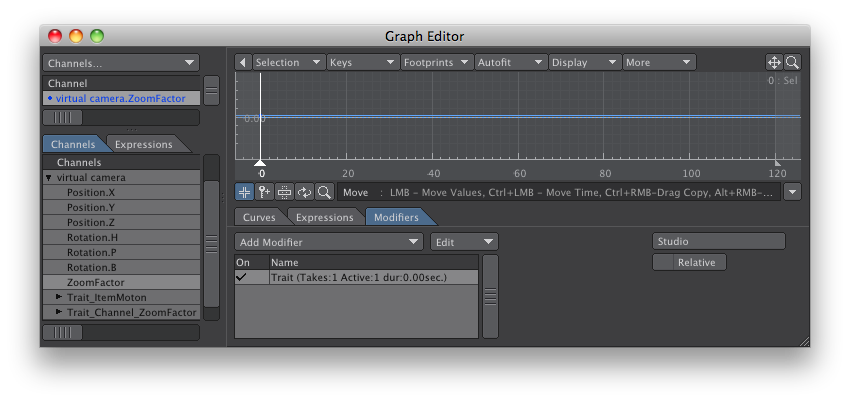
- We must adjust the node graph of the “.LegacyZoomFactor” trait only. Double-click its name to open its node graph. The target node has a single value called “Value”; this represents the trait’s value.
- Construct the following node graph. An explanation follows.

This zoom graph relies on the Motion controller’s ‘Move’ and ‘TPressure’ button data. The ‘Move’ track is a simple toggle where ‘1’ is pressed and ‘0’ is not pressed. The ‘TPressure’ track supplies values from 0 to 255 depending on how hard the user squeezes the ‘T’ trigger button. When you do not know what data values are possible for a track, look at the device manager panel in LightWave and highlight the device in question; the available data tracks and expected format will be displayed interactively.
The result of the graph will be this: zoom in when the ‘Move’ button is not pressed and zoom out when it is; the ‘T’ determines how quickly to zoom.
The logic node outputs a negative value when the ‘Move’ button is pressed having the effect of zooming out. The node output values act as a scaling to affect how fast the zoom will occur. This output is multiplied by the ‘TPressure’ value and sent to a “pow” node, which allows the zooming to appear more natural like that of a real camera zoom.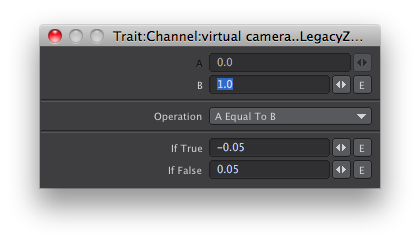
The previous zoom factor trait value is needed to give the node graph something to modify, since it applies a relative amount to arrive at a final absolute trait value. The Studio Trait node allows us to specify which trait to use. We choose the same trait for which this is a node graph for.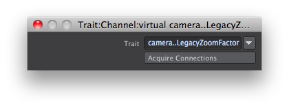
The previous trait value is combined with the ‘pow’ effect and clamped to keep the resulting zoom factor within a reasonable range.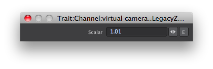
The above scalar affects how fast the zoom with occur. The value must be very close to 1.0.
This is a very basic zoom control. One enhancement is to add another logic node to allow multiple zooming speeds based on the amount the ‘T’ trigger button is squeezed. A gentle press to zoom very slowly and a hard press for maximum zoom speed.
Virtual Spotlight Motion
Similar to the virtual camera, the spotlight directly uses the gem motion.
- Create a spotlight type light called “virtual spotlight”
- Open its motion properties and add the “Virtual Studio Trait” modifier.
- In the studio, open its node graph.
- Create a device node set to the manager “PS3 Move.me” and device “PS3_Gem1”.
- Connect the device node XYZ and HPB to the trait node position and rotation respectively.
Virtual Spotlight Light Intensity
The gem can also be used to adjust the light intensity via additional buttons.
- Open the light properties and add an envelope to “Light Intensity”
- Attach the “Virtual Studio Trait” modifier to the channel in the graph editor.
- In the studio, open the new trait’s node graph.
- Construct the following node graph.
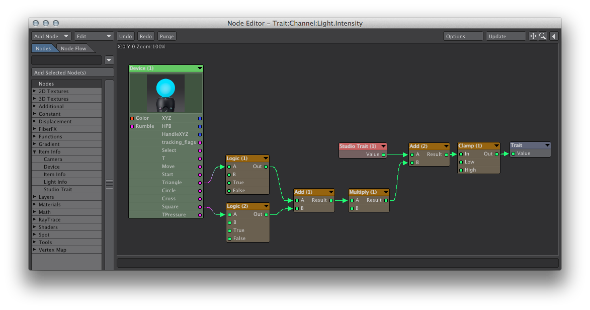
This node graph uses the gem ‘Triangle’ track to increase the light intensity while the ‘Square’ track decreases it.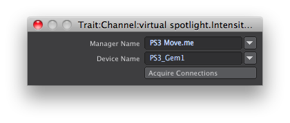

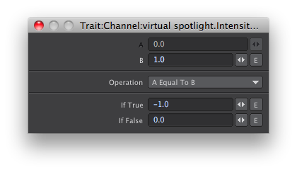
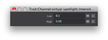
The light intensity is clamped between 10% and 98%.
Virtual Spotlight Cone Angle
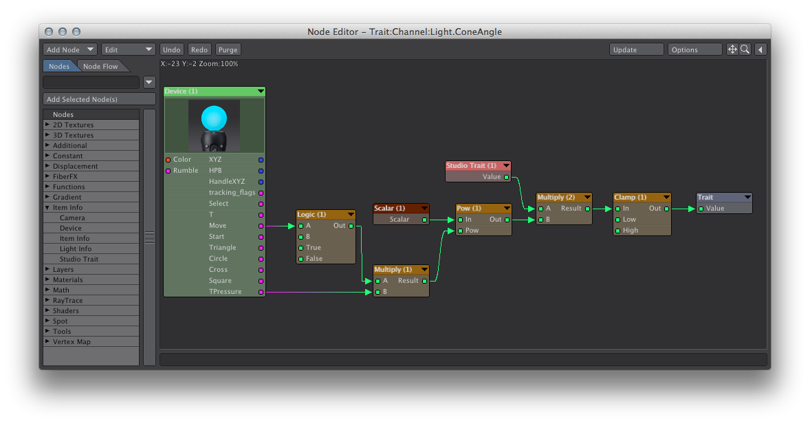
Similar to the virtual camera zoom, the spotlight cone angle can use the trigger and mode buttons
- Add a studio trait for the “Spotlight Cone Angle”. (Add “Virtual Studio Trait” to its channel)
- Construct the following node graph, which is very similar to the virtual camera zoom factor node graph.
Glossary
Behavior - An assignment of a device track to a LightWave command setup via the Control Booth panel.
Cast - A collection of characters
Cast Performance - A combination of various chosen character performances.
Channel - A device’s data stream
Character - A collection of traits.
Character Performance - A combination of various chosen takes for each trait in a character.
Character Preset - A definition of a character via its traits and connections to device channels and scene elements.
Character Track - The desired movement a character is expected to make as the scene progresses.
Collection - A container to better organize traits in the virtual studio and behaviors in the control booth.
Control - An interpretation of device channel data to cause an action. Controls can have child controls.
Control Booth - A feature that allows real world devices to issue commands in Layout.
Device - An data input/output container usually representing a real world physical control.
Device Manager - a manager of devices usually devoted to a specific method of communicating with them. The device manager panel accesses devices that are or have been available.
Device Track - A part of a device that provides or uses time-dependent data.
GEM - Motion controller used within the PS3 move.me application.
HID (Human Interface Device) - This is an industry standard to communicate with devices. The HID Manager supports this mechanism and provides access to devices that support it as well.
InterSense - An precise and range-limited motion tracking system.
LIVE - A 3D view port feedback mode that evaluates virtual studio traits many times per second without adjusting the current scene time.Performance - A particular arrangement of all traits such that they produce a desired result.
Preset - A collection of data used to remember settings applicable to specific aspects of the virtual studio. It’s purpose is to save the user time and grief while setting up their virtual studio.
Prop - A scene element that does not cause a response from a character, although, they can be manipulated by characters.
Device - A set of channels representing input. Typically, devices represent real world hardware.
Spike - A location marker for a prop or character.
Stage - A place to arrange the cast and props and define how the scene is to progress.
Studio Asset - A virtual studio setup that can be added as an asset to your existing scene.
Sword - An avatar used within the PS3 move.me application to represent a GEM.
Take - A recording of a trait value as it changes through scene time.
Trait - A scene asset that participates in the virtual studio.
Virtual Studio - A feature that allows real world devices control of scene assets.