Primitives - More
Bubbles
The Bubbles tool (Create > Primitives > More > Bubbles) provides a quick and easy way to create bubbles, rocks, stylized clouds, and a variety of other interesting objects. This tool replaces each selected point in your foreground layer with a sphere.
If no points are directly selected, the Bubbles tool will use every point in the foreground layer. Remember, more points mean longer calculation times.
To begin, create an assortment of points in the foreground layer. The Spray Points tool is particularly suited for this.
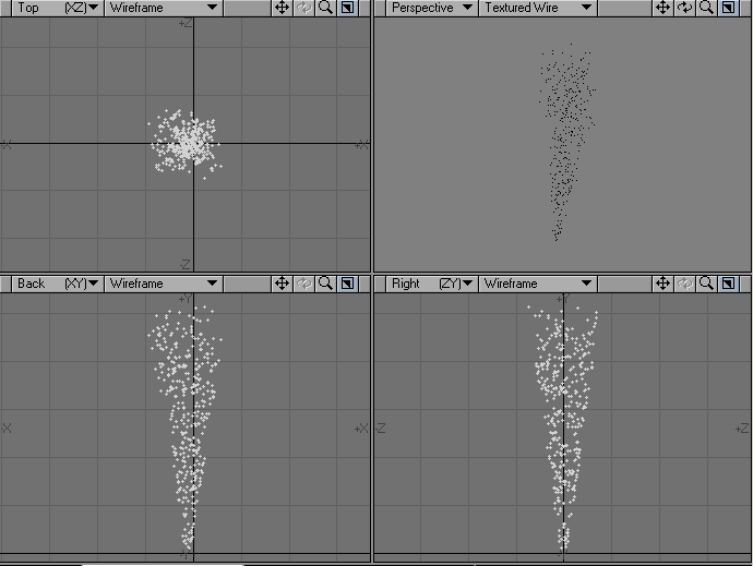
Once you are satisfied with the number and distribution of your points, select the Bubbles tool from the Create Tab in the Primitives section under More.
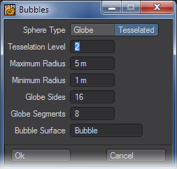
The options for creating the spheres are similar to those found in the Ball tool. Under Sphere Type, Globes are composed primarily of four-point polys (also known as quads) and can appear angular if they are created with a low number of sides or segments. Tessellated spheres are composed entirely of triangles and, using a comparable number of polys, will often yield smoother results.
If you choose Tessellated, the resolution of your bubbles will be determined by the Tessellation Level. Tessellation Level is similar to the Ball tool’s “Segments” setting, however, it is important to note that these settings are not identical. A Tessellation Level of 2 (which is the default) will produce significantly more polys than a Segment setting of 2 with the Ball tool.
The default Tessellation Level should work for most bubbles. However, higher numbers (i.e. 4 or 6) can be used for extremely detailed objects. Though a setting of 6 will produce unwieldy individual bubbles with more than 100,000 polygons each.
For Globes, the resolution of your bubbles will be determined by the number of sides and segments, which correspond to those in the Ball tool.
Tessellation Level has no effect when using Globe objects and Sides and Segments have no effect when using Tessellated objects.
The Bubbles tool uses its own internal routines for varying the size of each bubble it creates, however you can determine the largest and smallest bubble size by adjusting the Maximum and Minimum Radius settings.
For the best results, use the Fit All command (a) to show every one of your source points. Then reference your Grid size before entering the Radius settings. If you enter a Maximum or Minimum radius that exceeds your Grid size, your bubbles will frequently overlap and produce undesirable results.
You name the surface for the bubble objects in the Bubble Surface field. The default is Bubble, although you can choose any name.
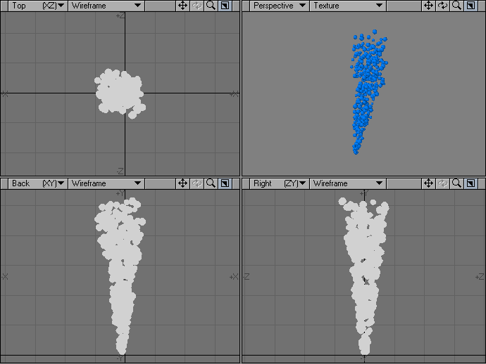
Once you are satisfied with your settings, click on the OK button. The position of each point will be recorded, after which the points will be deleted and bubble objects of varying size will be created in their place.
The Bubbles tool requires one undo for every bubble it generates, which means that running this tool on a large number of points may be impossible to fully undo. If you want to test different Sizes and Sphere settings, you should copy and paste your points to a new layer before running the Bubbles tool.
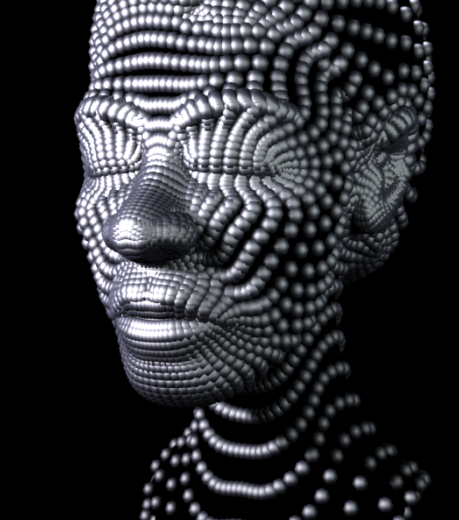
The Bubbles tool uses the points in the foreground layer, however polygons are ignored. As such, it is possible to achieve interesting results by running the Bubbles tool on one of your existing objects.
Platonic Solid Tool
The Platonic Solid tool is located in the Create Menu Tab under the Primitives group. This tool is very easy to use and can really speed up the modeling process. A platonic solid, as denoted by Euclid in the last proposition of his seminal mathematics textbook The Elements, is a polyhedron whose faces are all congruent regular polygons, and where the same number of faces meet at every vertex. The best known example is a cube (or hexahedron) whose faces are six congruent squares. Platonic solids are often used as a dice in role playing games, so if you want to make a D4, D6, D8, D12 and D20 easily, this is the tool for you!
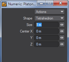
The Shape pop-up menu on the Numeric Panel controls the shape of the object. It gives you seven primitive shapes to select from.
The choices are:
-
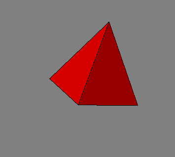
- Tetrahedron - the simplest of the platonic solids made with just four triangles.
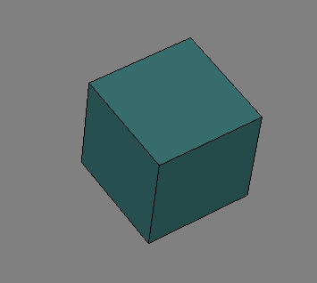
- Cube - the best known of the platonic solids, otherwise known as a hexahedron.
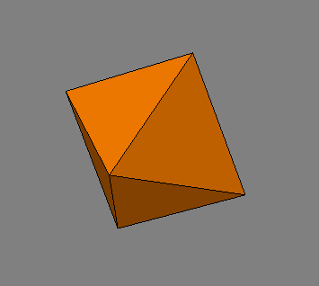
- Octahedron - an eight-sided object.
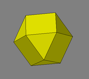
- Cubeoctahedron - Although this panel is named the Platonic Solid tool, a Cubeoctahedron is not actually a platonic solid.
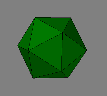
- Icosahedron - a 20-sided object made with triangles.
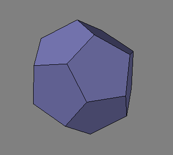
- Dodecahedron - a 12-sided object made from pentagons.
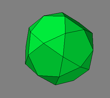
- Icosidodecahedron - This one isn’t a platonic solid either!
You can drag the center position handle to move the shape, and you can drag the outer bounding box edges to resize it. You can also use the numeric window to accomplish these options.
Wedge
The Wedge function (Create > Primitives > More > Wedge) will generate an annulus (like a flat donut).
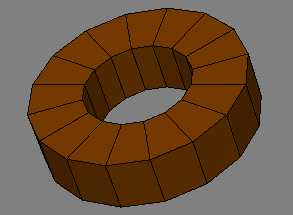
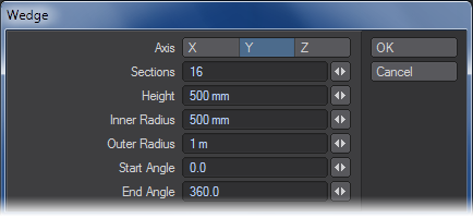
- Axis - Axis is the axis perpendicular to the doughnut hole.
- Sections - Refers to the number of radial sections to use for the object.
- Height - Specifies the width of the object.
- Inner Radius - Specifies the radius of the inner hole.
- Outer Radius - Specifies the radius to the outside perimeter.
- Start Angle - Start Angle is the starting angle around the selected Axis.
- End Angle - End Angle is the ending angle around the selected Axis (360 for a complete doughnut).
Gear
The Gear function (Create > Primitives > Gear) creates a gear-shaped object. This tool is very similar to the Gears function (discussed next) but has fewer options.
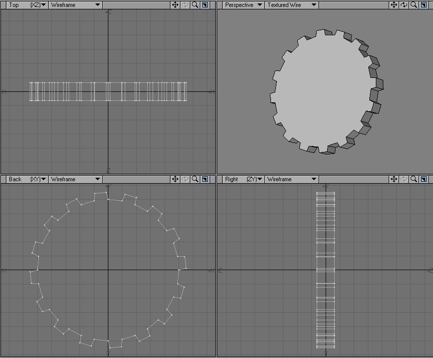
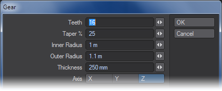
- Teeth - Refers to the number of teeth in the gear.
- Taper % - Sets the “pointiness” of the teeth. A higher setting creates sharper teeth.
- Inner Radius - Refers to the distance from the center of the gear to the bottom of the teeth.
- Outer Radius - Outer Radius is the distance to the outside edge of the teeth.
- Thickness - Thickness is the width of the gear.
- Axis - Axis is the perpendicular axis of the gear.
Gears
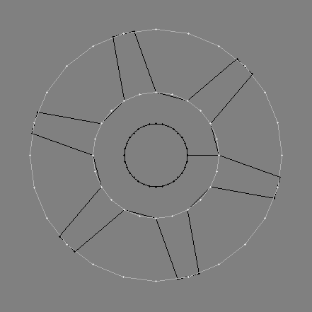
True to its name, the Gears tool (Create > Primitives > More) quickly creates gear-shaped objects. Before describing the controls, let’s first take a look at what’s happening behind the scenes.Gear objects are composed of a disc shaped object with protrusions called “teeth.” Each tooth is made up of four points.
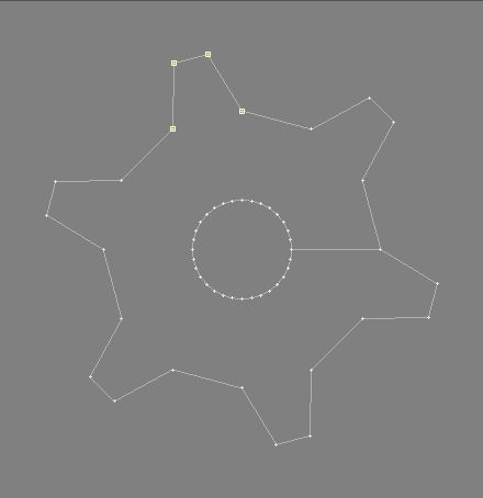
Two points comprise the base of each tooth, and two the top. Therefore, a gear with two teeth would be made up of 8 points, a gear with four teeth would consist of 16 points, and so on.When you run the Gears tool, it first looks at the number of teeth you requested. It then multiplies the number of teeth by four (the number of points required for each tooth) and creates a disc using this total number of points.
The diameter of the disc is determined by you, and is called the “Inner Radius.”
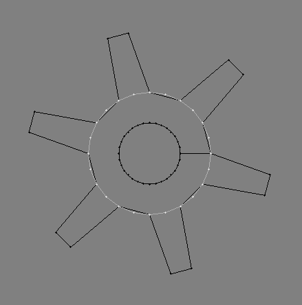
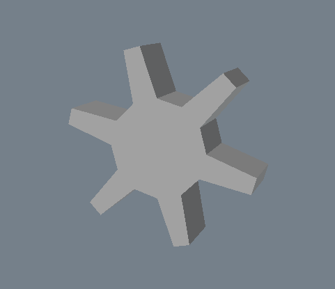
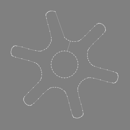
Here you can see that a disc with 24 points has been created. At four points per tooth, this will yield a gear with six teeth. An existing gear with six teeth can be seen in the background.Once the disc has been created, pairs of points are selected and moved outward. The position these points are moved towards is determined by you, and is called the “Outer Radius.”
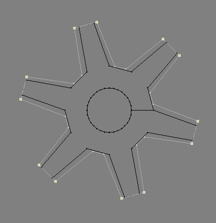
Finally, the four points comprising each tooth are tapered by approximately 65%.
Once the basic gear shape has been created, it is extruded to a Thickness specified by you.
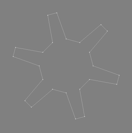
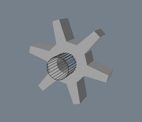
To complete the gear, a hole is punched out of the center. This is accomplished by the creation of a disc whose diameter is exactly half the size of the Inner Radius. It is extruded, placed in the background, and used as a cutting template for a Boolean Subtract operation.
This entire process happens internally, and is transparent to you. Now that we’ve looked at how gears are created, let’s take a look at the controls offered by this tool.
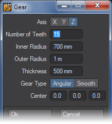
The first row of buttons determines the axis the base gear object will face once it has been created. It also determines the axis along which the gear object will be extruded using the Thickness setting (mentioned below).
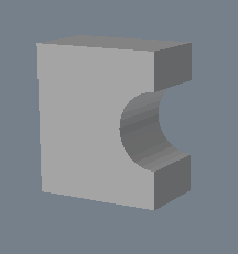
The Number of Teeth enables you to set the number of teeth your gear will have. Note that at least three teeth are needed for a usable gear, and that entering 1 for the number of teeth will not result in a gear at all, as shown below.
The Inner Radius determines the diameter of the gear’s base. This is the location from which each of the teeth will project outward.
The Outer Radius determines the length of the gear’s teeth. This is the location that the two points forming the top of each tooth will move towards. Note that it is possible to make the Outer Radius smaller than the Inner Radius. Doing this will still create a gear shape, although the teeth will appear to taper outward rather than inward.

The Thickness field determines the depth of the gear, which is the amount that the gear will be extruded. Note that the extrusion occurs along the Axis set by you at the top of the window.Under Gear Type, Angular is the default option, and creates gears using the method described above. Smooth uses the Inner and Outer Radius to interpolate a smooth arc between the top and bottom of each tooth.
Bear in mind that smoothing is computationally intensive, and will take longer to calculate. Also, it will create an object with a higher number of points and polygons. Finally, the Center option determines the exact center for your gear, which can be useful for positioning gears that are offset precisely from one another. The three fields correspond to the X, Y, and Z axis respectively.
Gemstone
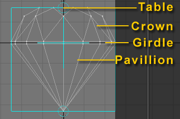
You can quickly make a nice round-cut diamond with the Gemstone Tool (Create > Primitives > Gemstone Tool).
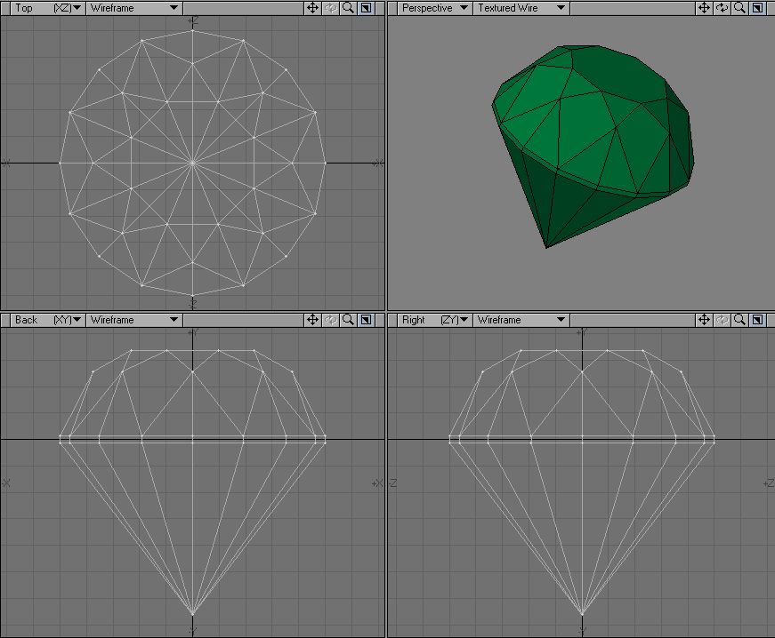
On the Numeric Panel you can control various aspects of your diamond. Center sets the center position and Radius the overall radius of the object.
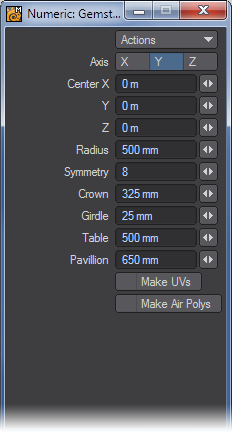
Higher Symmetry values increase the number of polygons used on the crown and lower values decrease the number. The Crown, Girdle, Table and Pavillion settings control the size of those areas on the diamond. (See illustration below for reference.)
Make UVs
The Make UVs option at the bottom of the various primitive Numeric Panels assigns some default UVs based on the geometry of the object. Note that a UV Texture Map must be currently selected or this option will be ghosted.
Make Air Polys
Make Air Polys will create duplicate polygons facing inside the Gemstone with the surface name of “Air”. This is a throwback to LightWave's original camera, no longer included. It should only be used for export to other engines that cannot deal with volume stacking.
SuperQuadric
Use the SuperQuadric tool (Create > Primitives > SuperQuadric) to create quadrics objects interactively. You can choose between two shapes: Ellipsoid (spherical) and Toroid (doughnut).
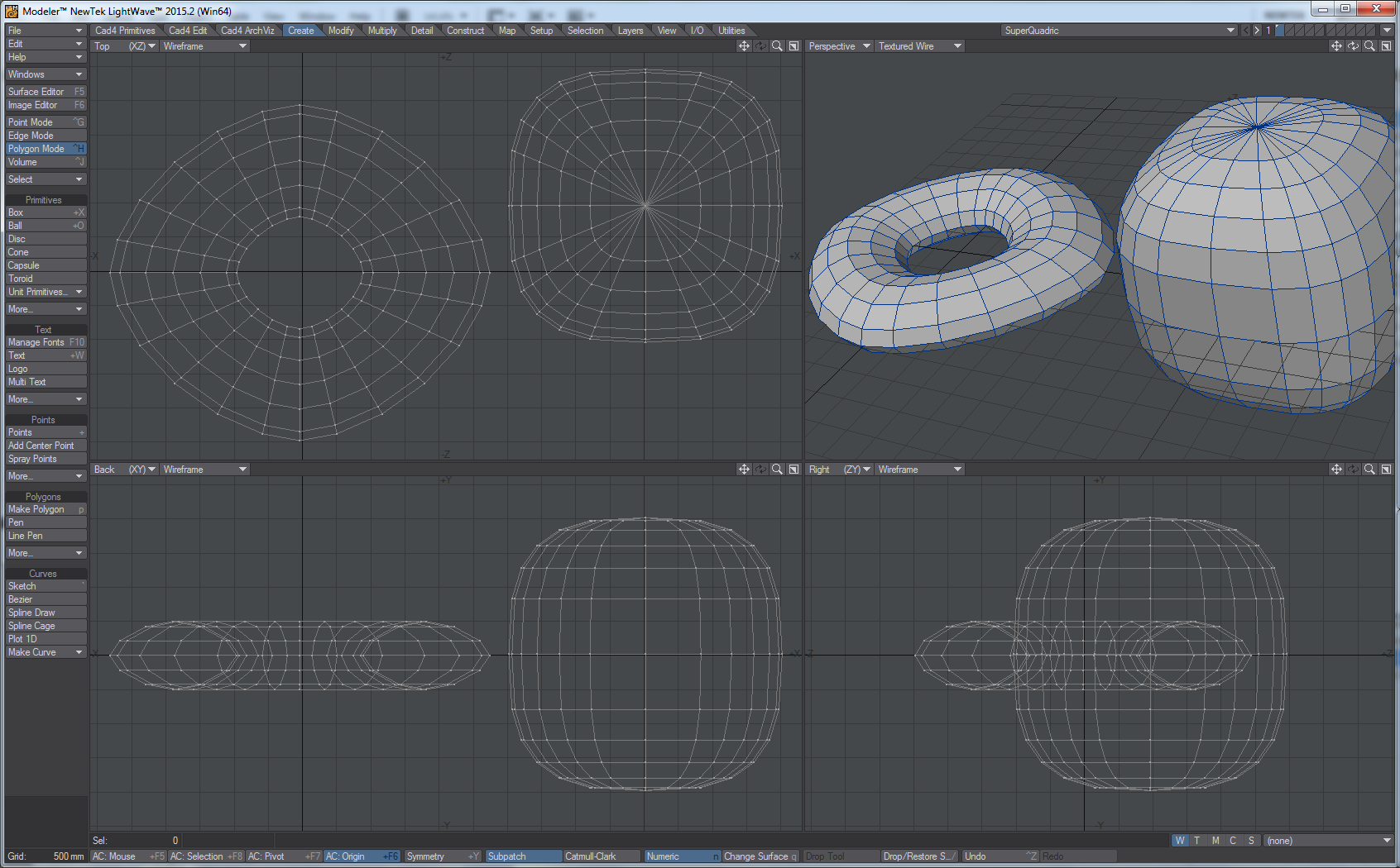
Toroid on the left, Ellipsoid on the right (with Top and Side Bulge set to 3)
Ellipsoid
You can use standard drag handles to manipulate the shape and position interactively.
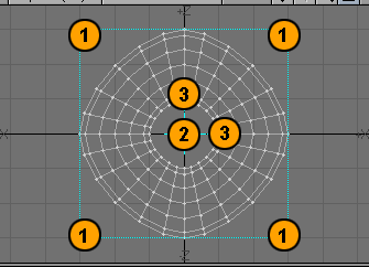
- Interactively sizes the object by clicking and dragging here with the LMB .
- Interactively Center the object by clicking and dragging here with the LMB .
- Interactively sizes the Hole in the object by clicking and dragging here with the LMB .
The Numeric Panel provides more detailed control.
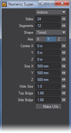
- Axis - determines the major axis for the object. This is also set when you click to first create the ball using the axis perpendicular to the (orthogonal) viewport.
- Sides - determines how many horizontal segments should be used around the Object.
- Segments - sets how many vertical segments should be used.
- Center - The XYZ coordinates of the center of the Object.
- Size - Overall dimensions of the object.
- Hole Size - This option is only available for the Toroid Shape. This setting defines the inner radius of the toroid.
- Top Bulge - This setting defines the vertical curvature of the geometry.
- Side Bulge - This setting defines the horizontal curvature of the geometry.
- A perfect circle - looking along the set Axis - can be made by setting the Side Bulge to 2. A value of about 5 yields a rounded square shape.
Make UVs
The Make UVs option at the bottom of the various primitive Numeric Panels assigns some default UVs based on the geometry of the object. Note that a UV Texture Map must be currently selected or this option will be ghosted.
A quadric is a shape made of the squares of the coordinates, a generalization of a sphere, which is x2 + y2 + z2.
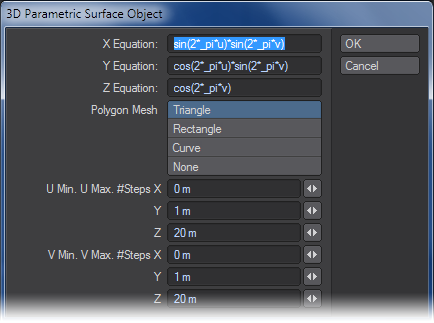
Parametric Surface Object
The Parametric Surface Object function (Create > Primitives > ParametricObj) creates parametric surfaces based on the equations entered for X,Y, and Z in terms of UV coordinates. The function lets you create the object using Triangles, Rectangles, Curves, or just points (None).
Plot 2D
The Plot2D function (Create > Primitives > Plot2D) generates a two-dimensional surface in the XY plane consisting of Triangles, Rectangles, Curves, or points (None). The height (in the Z direction) is determined by the value of the expression in the Equation field at each division in the X and Y axes.
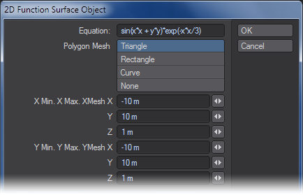
In the fields labelled X Min, X Max, Y Min, and Y Max, enter the boundaries for the surface. In the XMesh and YMesh fields, enter the number of divisions along that axis.
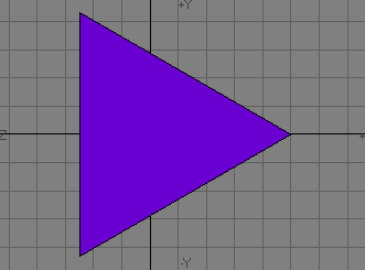
Equilateral Triangle
Equilateral triangles are three-sided polygons whose sides are all equal in length. The Equilateral Triangle tool is found under Create > Primitives > More.
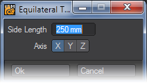
Side Length determines the size for each of the triangle’s sides. The Axis buttons determine the direction along which the polygon’s normal will run, or simply, which way the triangle will be facing.
You also can create an equilateral triangle using either the Ball or Disc tool. If you hold down the Ctrl key or use the middle mouse button to drag out a circle in one viewport, you will constrain the width and height, ensuring a perfect circle. Now click N to bring up the Numeric Panel and set Sides to 3.
Using this technique, you can quickly and interactively create perfect triangles, diamonds, pentagons, hexagons, etc.
StarSphere
When you want to create a starfield with parallax, you can sprinkle some points around, convert them to polygons and give them surface names, but why bother? NewTek engineers have done all the hard work for you with StarSphere. This generates up to nine layers of single point polygons which all have different levels of magnitude allowing you to create convincing starfield models quickly and easily.
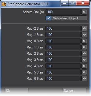
The first parameters to set are how big you want the StarSphere to be and whether you want it spread over nine layers, or have it compressed down to one. The remaining settings are how many of each sort of star you wish to have in your StarSphere. Actual magnitude distributions are hard to come by and vary from location to location, so the default settings have been left at 100 stars of each magnitude, but it’s likely that you will have far fewer bright stars than faint ones, so your lower magnitude stars (Magnitude 2 - 6) should probably vastly outnumber your brighter stars (Magnitude -2, - 1).
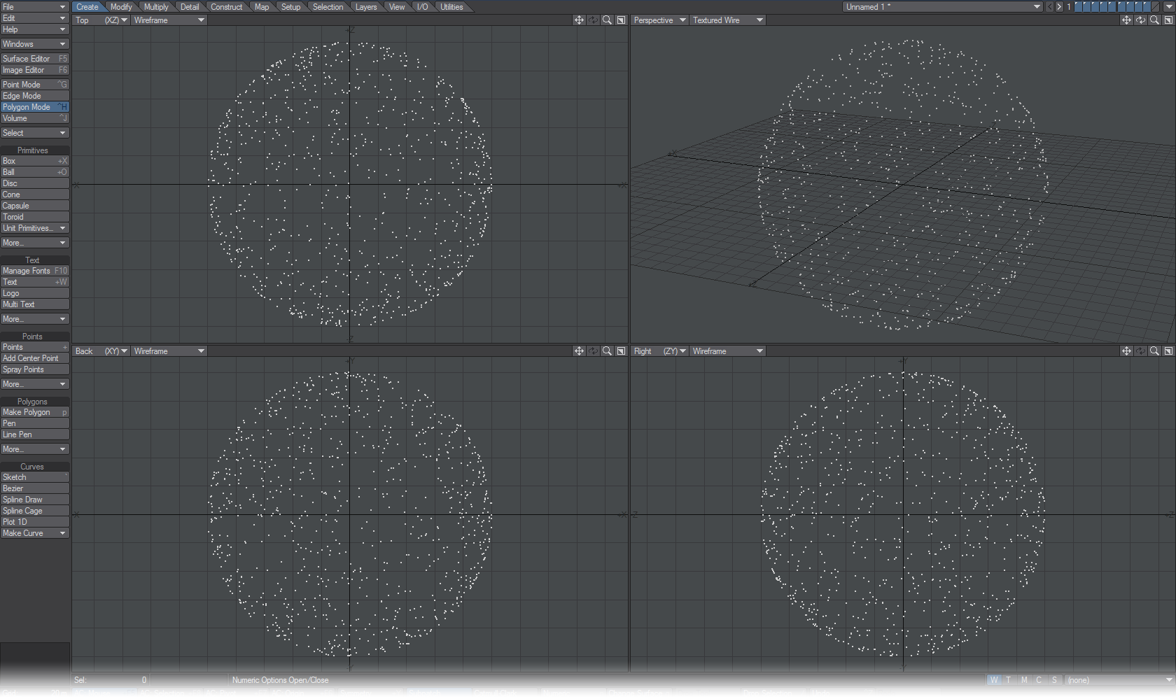
Using the StarSphere Generator will create a new object.