Introduction to 3D printing with LightWave
Modeling for 3D printing is a new discipline for many with LightWave and requires a certain rigor. Models need to be watertight, otherwise known as manifold. This means that they are a solid continuous surface with no holes. You can’t use any of LightWave’s tricks, like subpatching or double-sided polygons, everything needs to be present in the model but equally you do not need to worry about polygon topology.
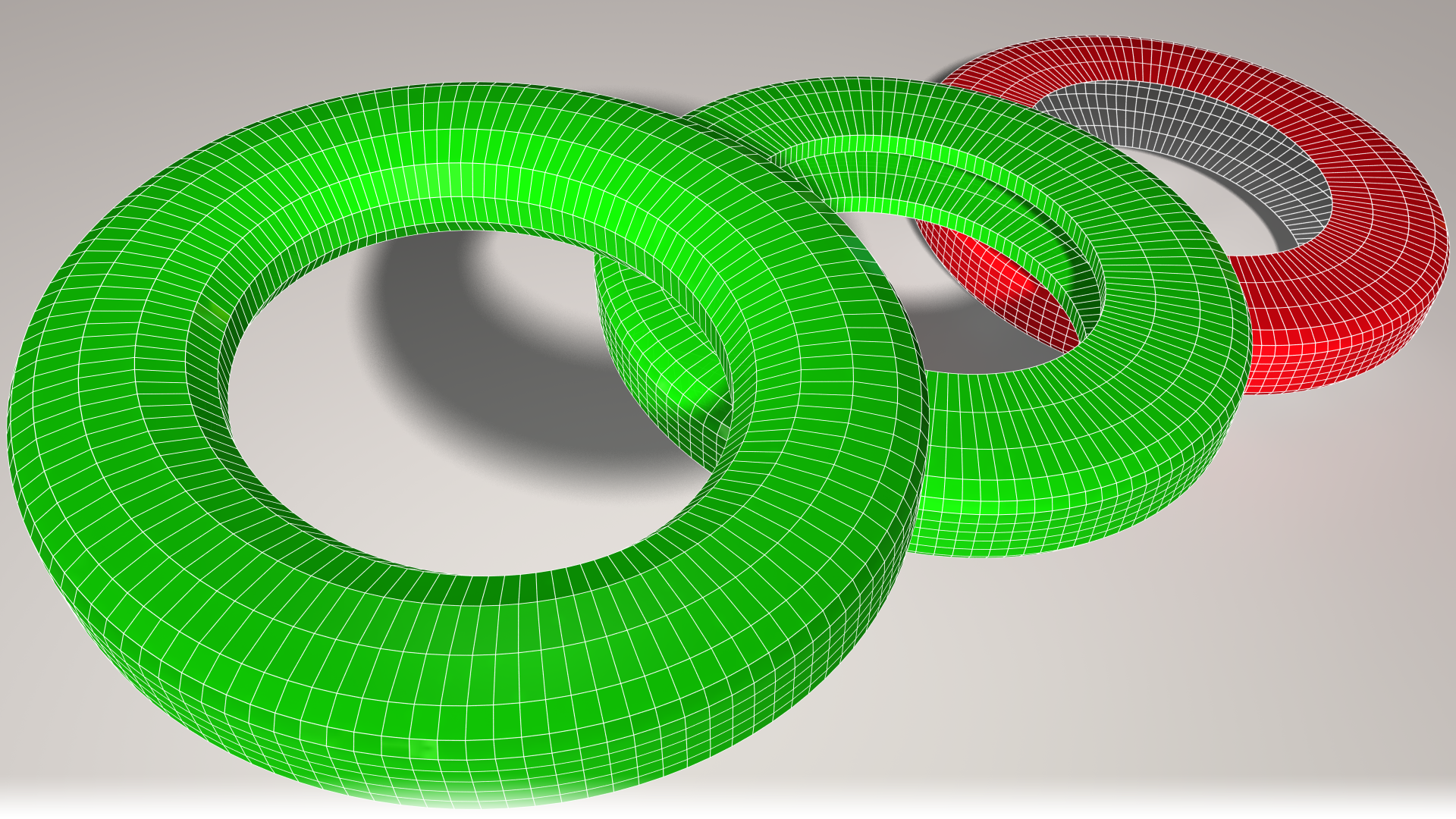
The first ring is manifold, there are no holes. The second is manifold too. The ring is hollow but the polygons are thickened. Our third ring is not acceptable as an object for 3D printing. Because LightWave’s polygons are single-sided, the inside of the ring counts as a big hole, even if it has been surfaced as double sided.
The next important factor is that there can be no intersecting polygons - that’s to say polygons that pierce others without being connected.
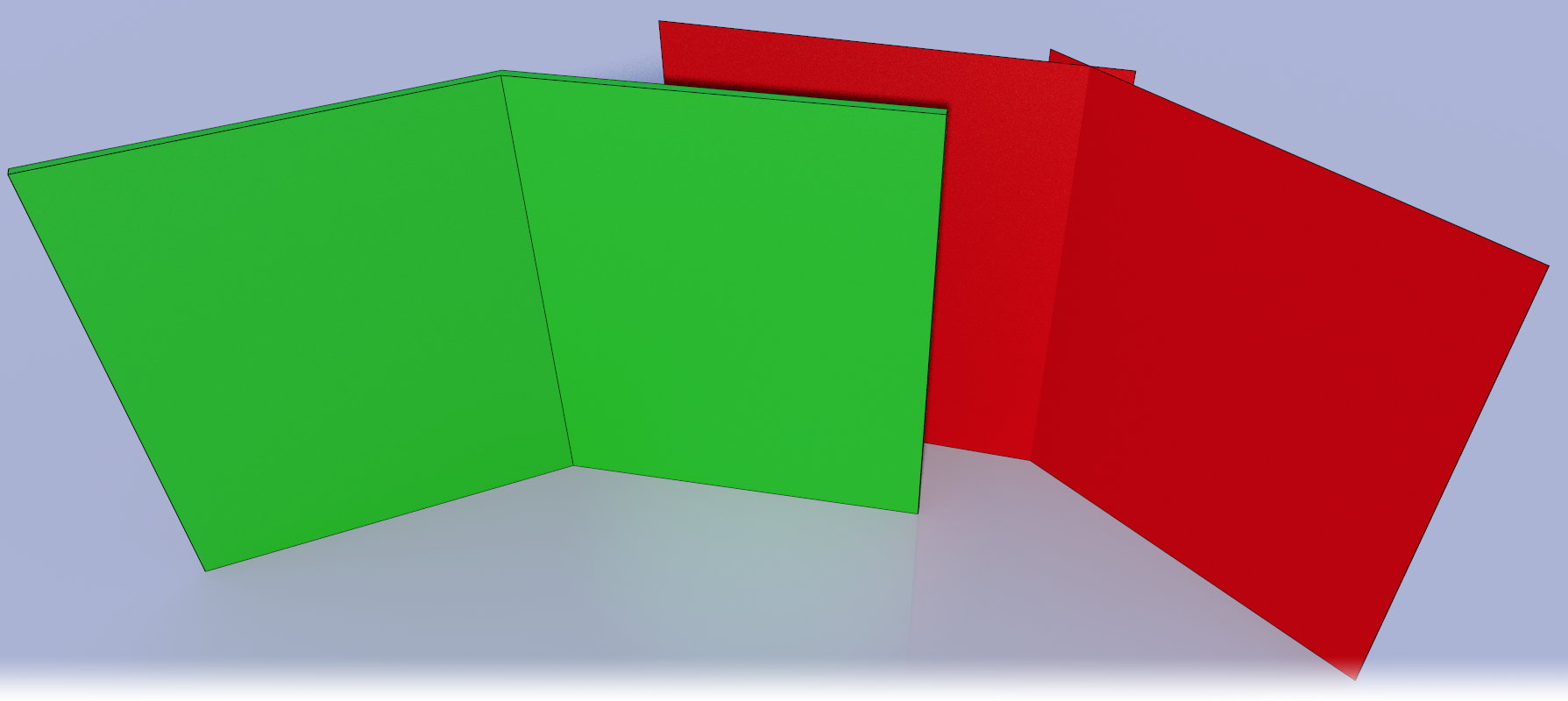
The green fold on the left will print well. It has at least 2mm thickness and the fold in the center is contiguous. The red object on the right won’t. The two polygons share nothing and have no thickness.
Upresing
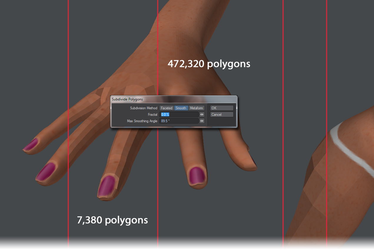
When you print a model with too few polygons, it can look faceted in print. If this isn’t the look you are going for, you can subpatch your object and then freeze it. However, this will reduce the size of finer details as they respond to the subpatching algorithm. A better way to reduce faceting can be achieved by using the Subdivide tool set to Smooth. Subdivide needed three iterations to get to an acceptable level of smoothness across this mesh, going from 7,380 polygons to 472,320.
Example: Preparing the Alien Emissary for 3D Printing
We wanted to test LightWave’s capabilities for 3D printing by sending our Alien Emissary model straight out of LightWave to Shapeways (http://www.shapeways.com/) 3D printing service for a full-color 3D print.
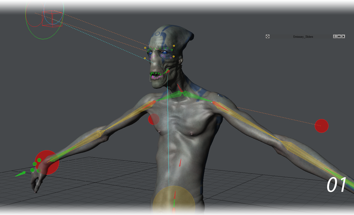
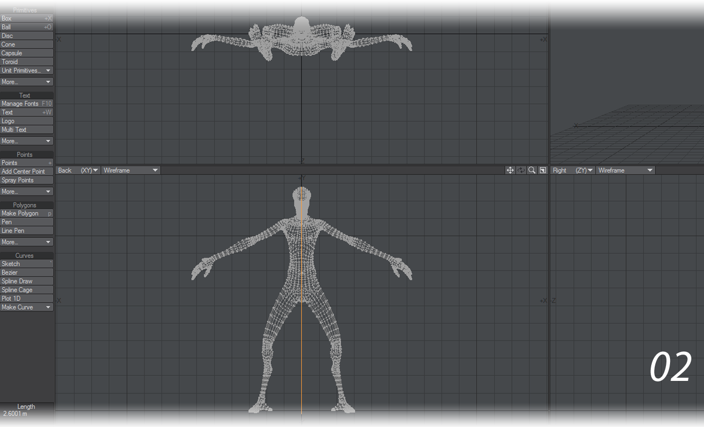
- We started with the Alien Emissary from the LightWave 10 Content Directory. The scene file came complete with a character object, TIF texture maps, and a rig that could be used to pose the mesh (01). The mesh was 2.6 meters tall. This is an appropriate height for an alien character, but too tall for a small statue meant to fit on a shelf. The model would have to be scaled at a later point (02).
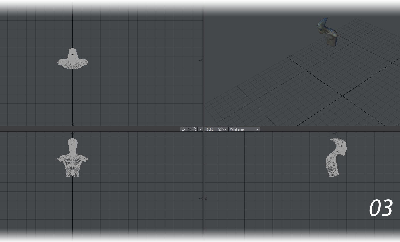
- A bust statue does not require arms or a lower body, so we chopped off the arms and all geometry below the lower torso (03). The mesh was not scaled at this point, because we wanted the option of posing the character with the existing rig.
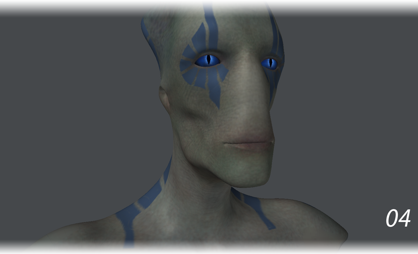
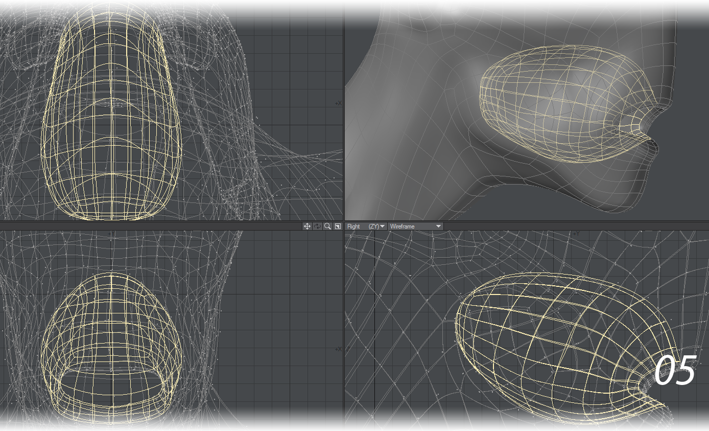
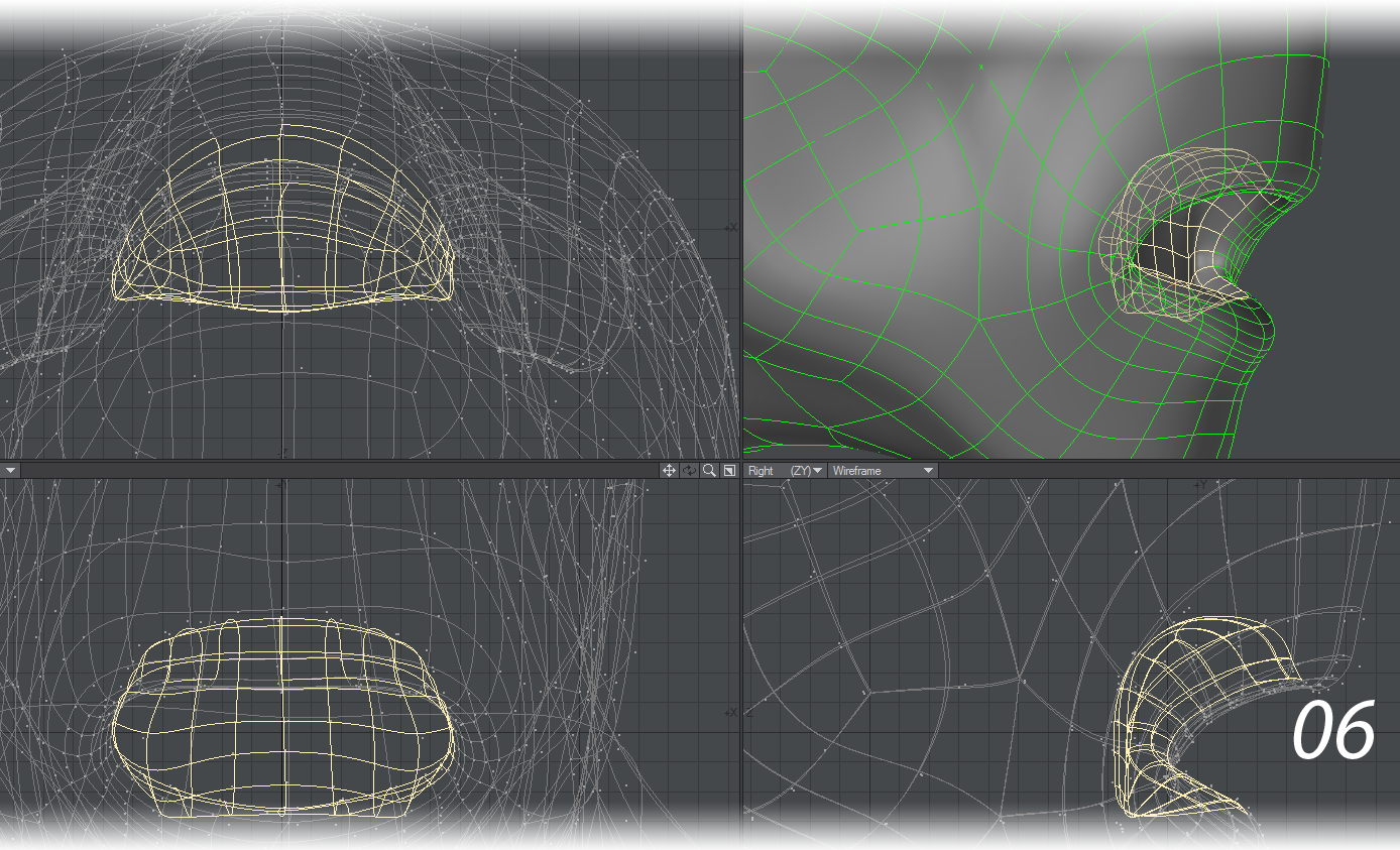
We also created an endomorph that could close the mouth and reduced the size and number of polygons in the mouth cavity to make it more suitable for a print (04-06).
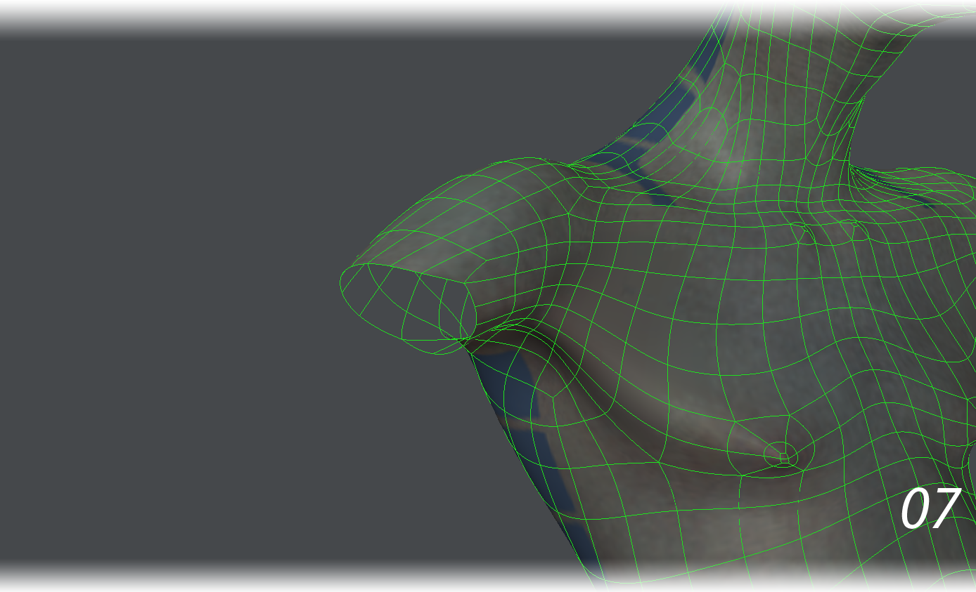
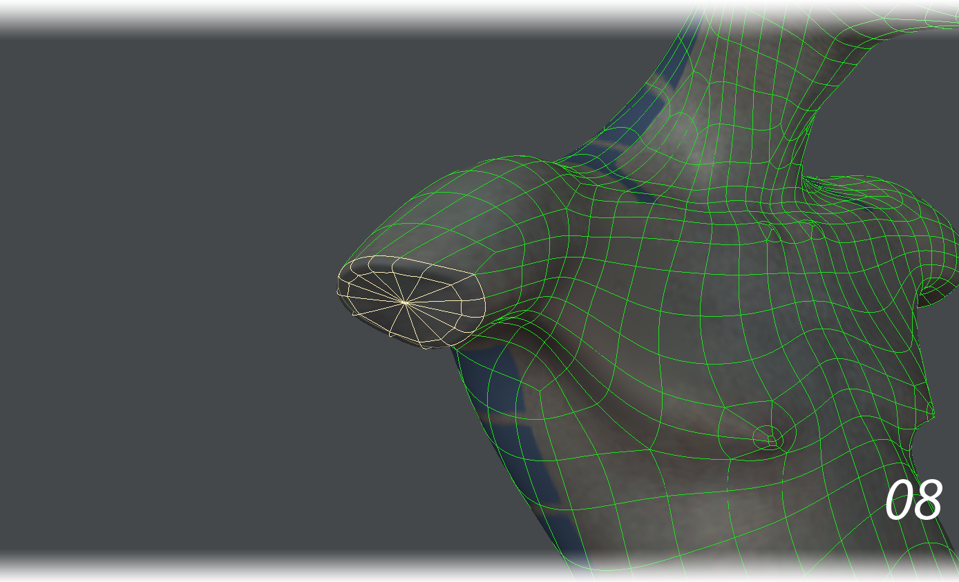
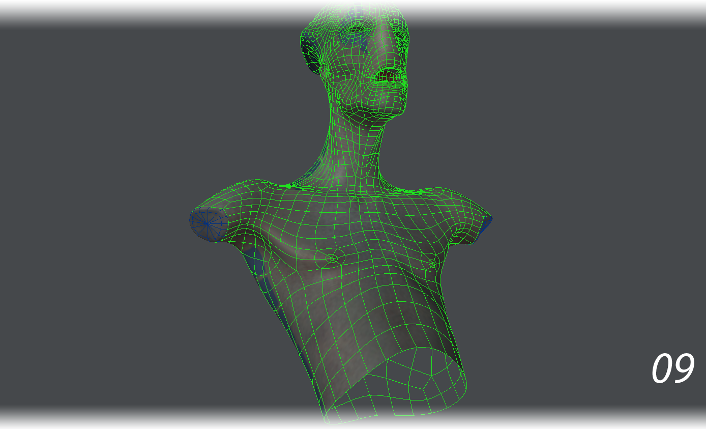
- A shell with no thickness cannot print (07). The arm holes needed patching. We patched the arm holes using Make Poly. Then used Bevel to give these n-gons a bit of an inset, then the Spikey Tool with a 0% Spike Factor to convert the n-gons into triangles. The results spackled over the arm holes nicely (08).
Although the arm holes were now sealed, the alien was still a shell with no thickness. It had a large, open hole at the bottom.
One solution might have been to patch over this lower torso hole, sealing it off and fulfilling the “watertight” mesh requirements for 3D printing. However, a solid torso would have used a lot more material and cost a small fortune. In 3D printing, the less material used, the less costly the print. A hollow torso would not only make for a lighter statue, but also a cheaper print.
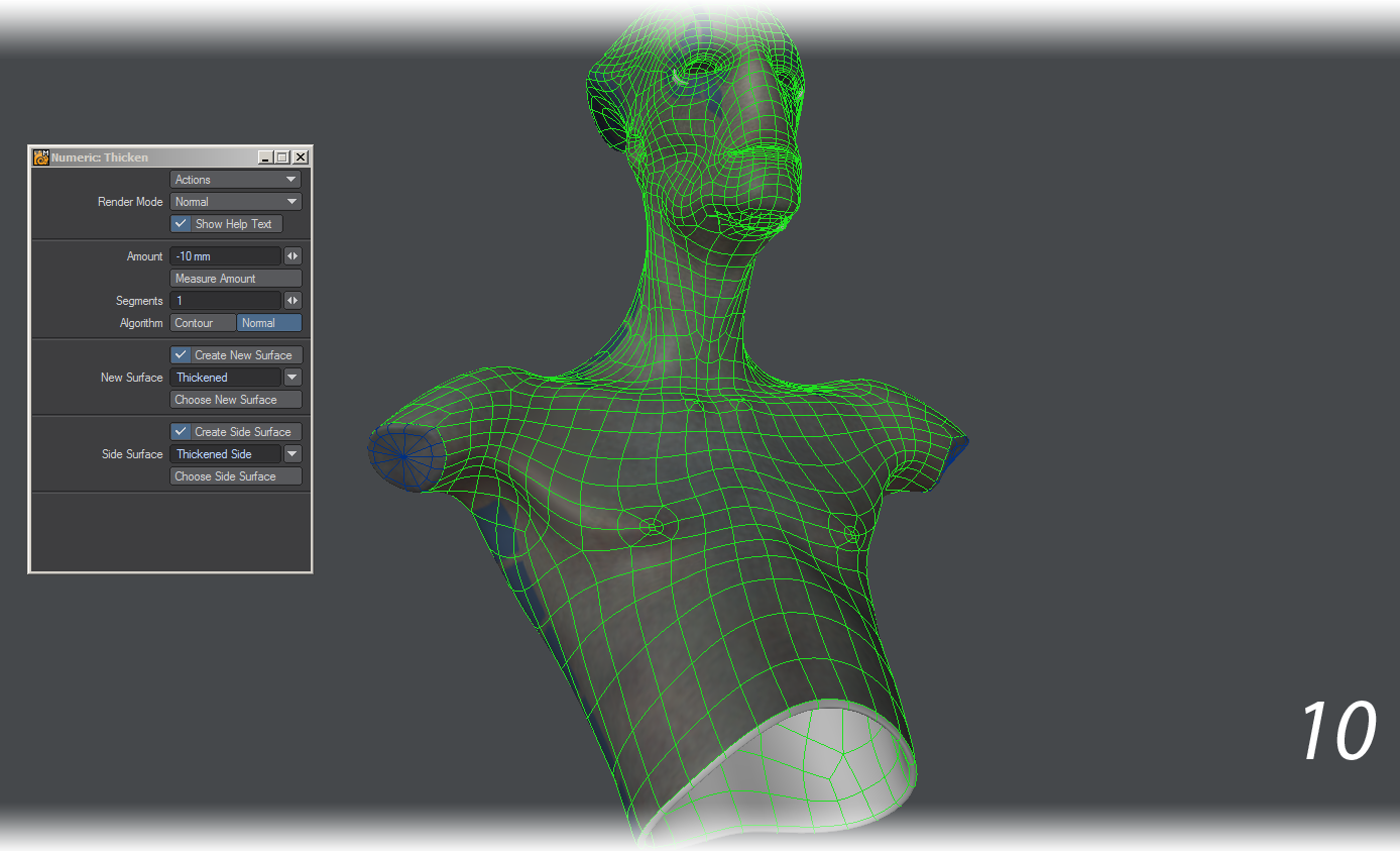
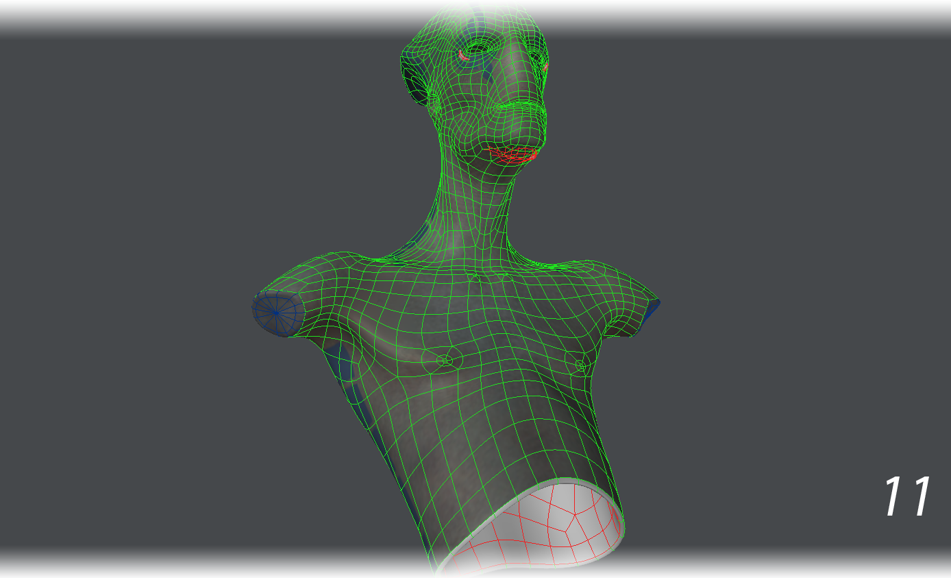
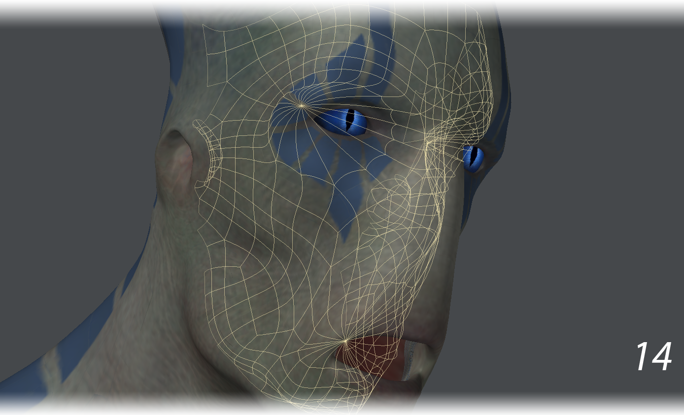
We used the Thicken tool to create an inner surface and a reasonably thick wall. Mindful that this alien would be scaled down to about 25% of its original size for printing, we thickened the alien by 10mm. This way, when the alien was scaled down to a quarter of its size later, the wall thickness would not be too thin for printing (10). We also turned on the checkboxes for Create New Surface and Create Side Surface to make the new geometry easier to select and manipulate and gave the Thickened surface a different wireframe color. This made it easy to see intersections in the geometry, for example the eye and chin areas (11).
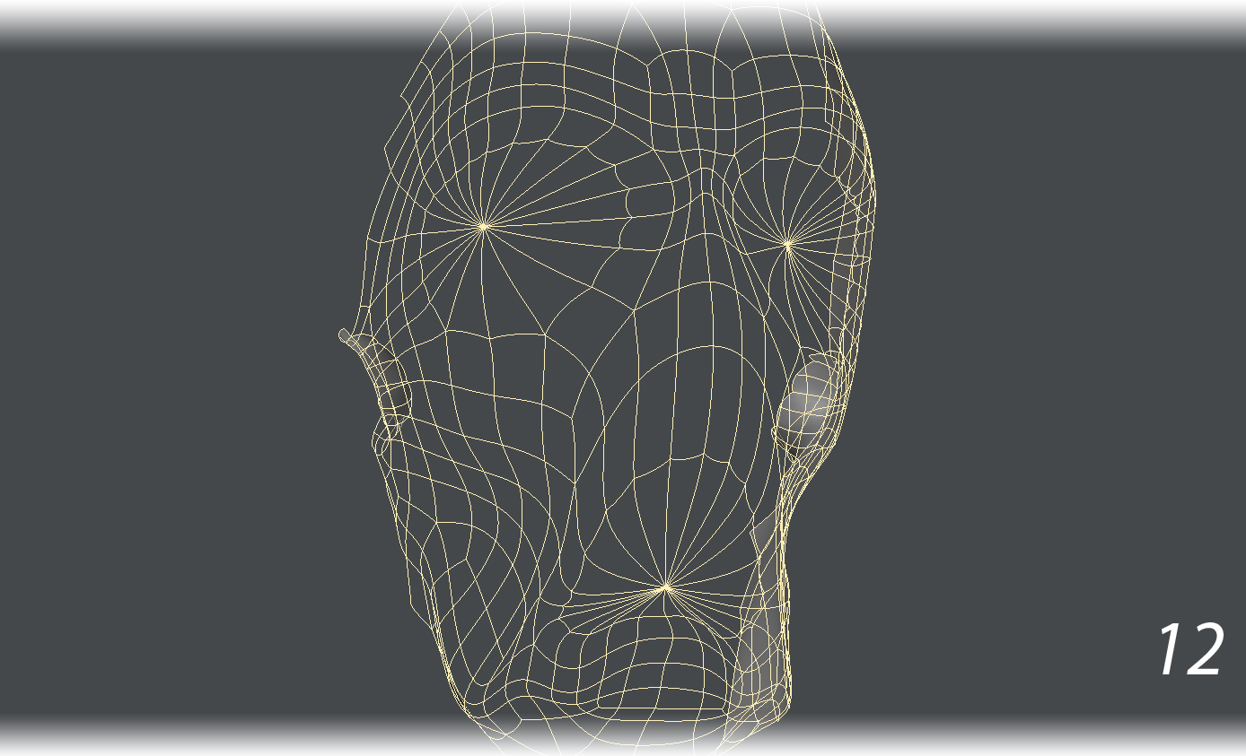
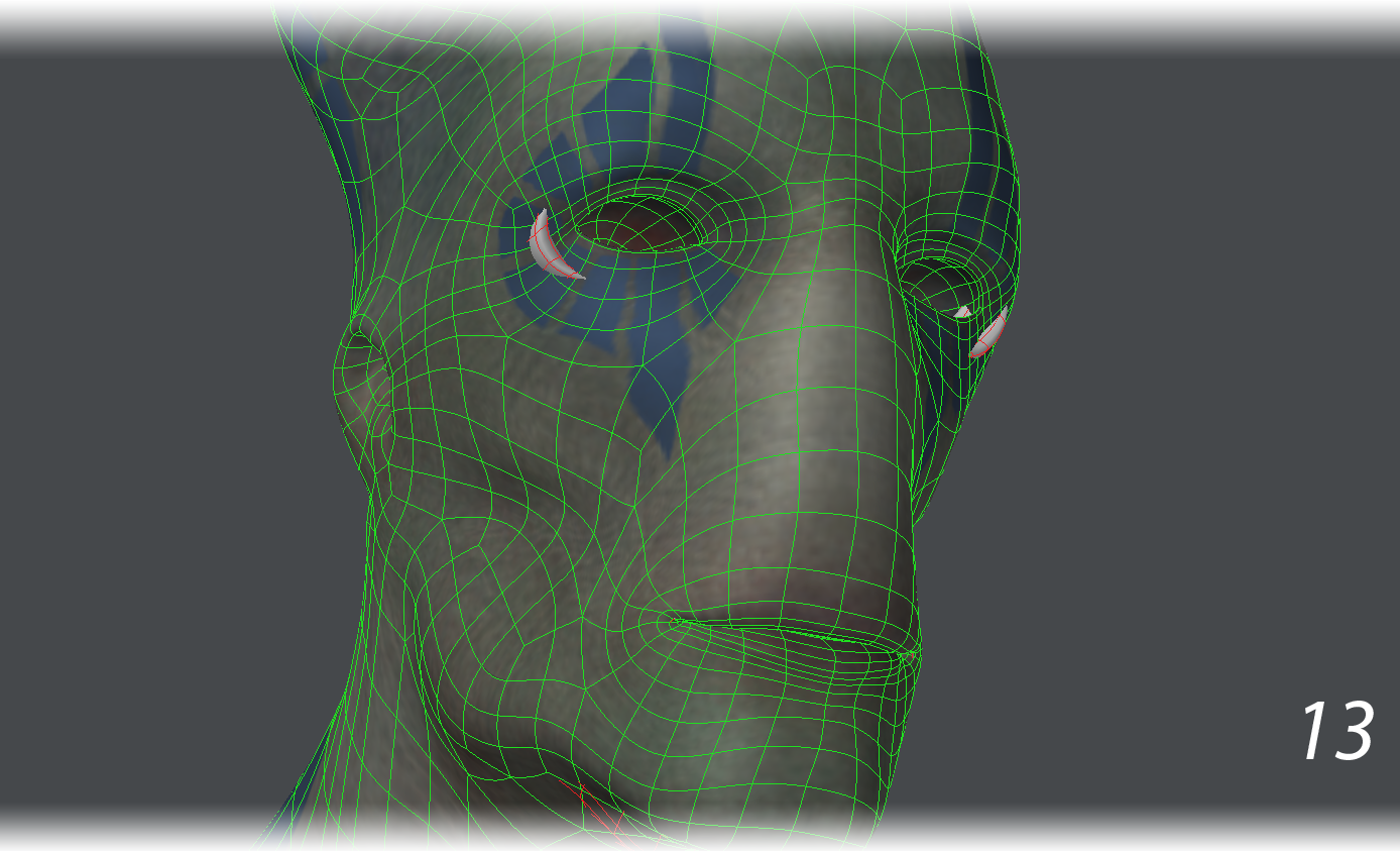
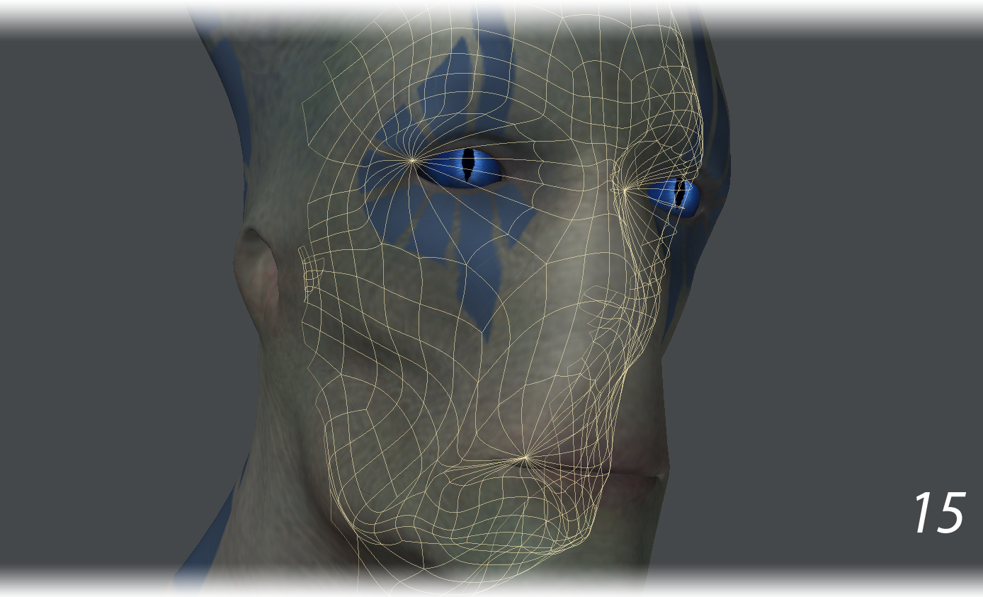
- The interior sides of the eye socket, chin and mouth cavity geometry were simplified and smoothed out so that they would not intersect the outer geometry. The endomorph to close the mouth also needed some tweaking on the chin geometry (12-15).
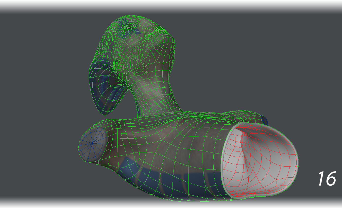
- The alien now had a watertight mesh that could be printed if scaled down to fit the printing bed. There was just one problem: gravity. This mesh had nothing to hold it upright after printing. At best, it could rest on its back if printed (16).
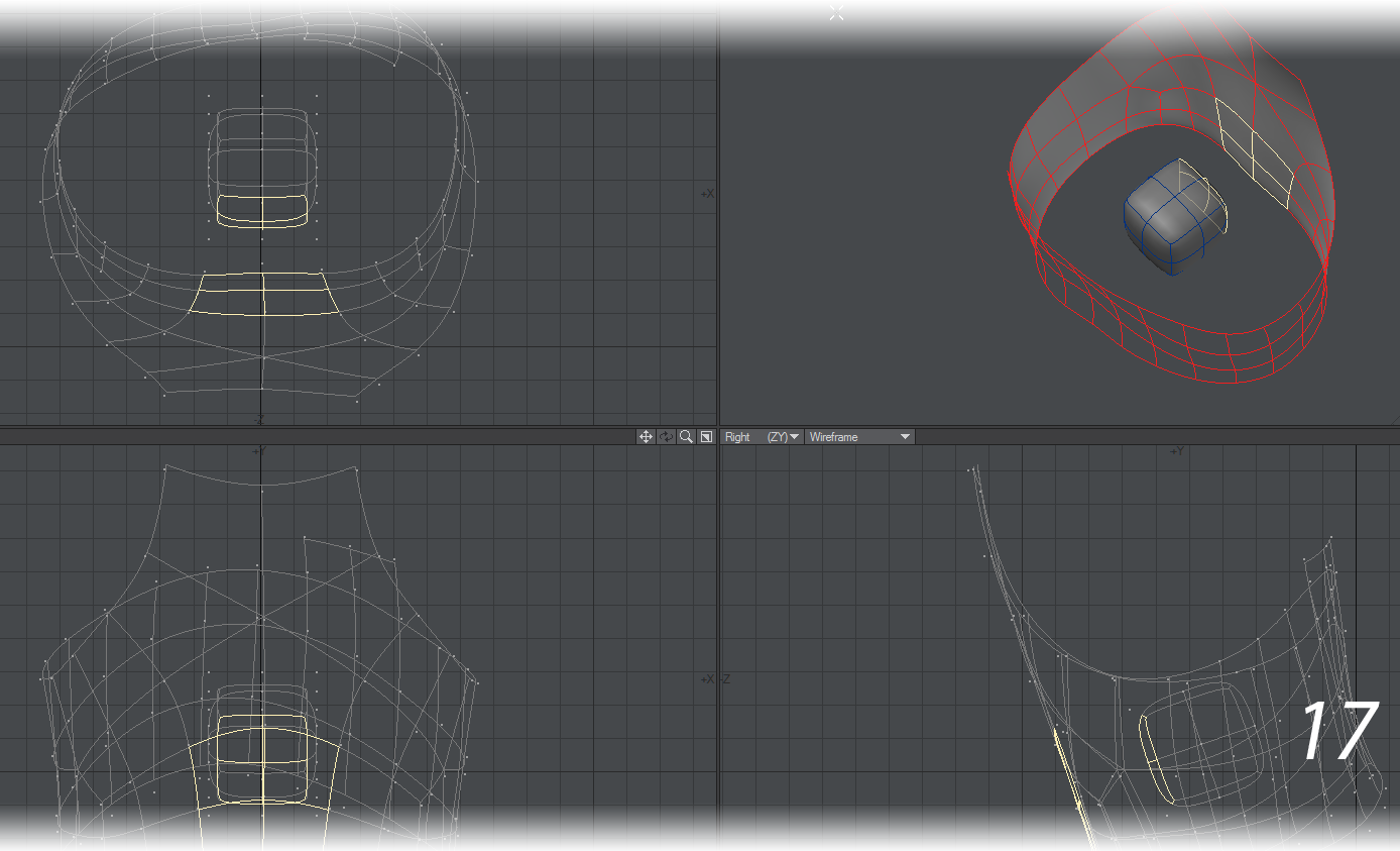
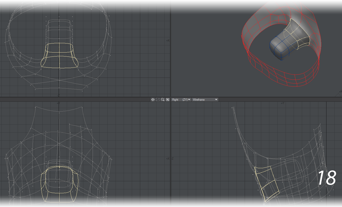
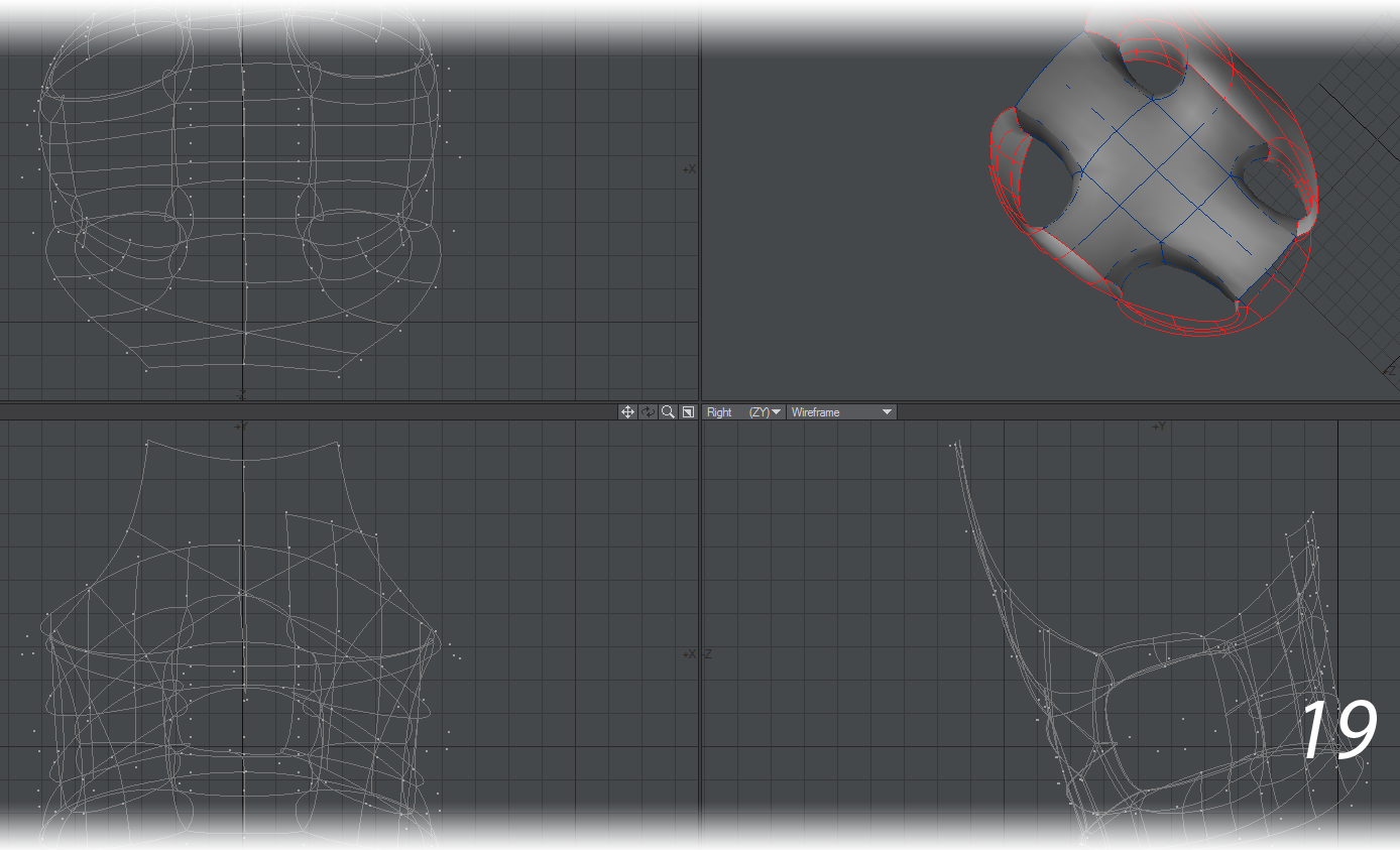
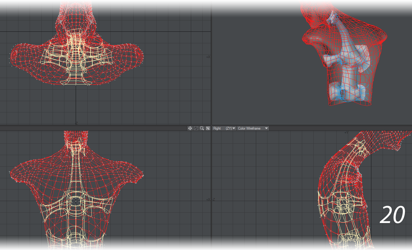
It would need a pedestal. It would also need a structure inside it that could connect it to that pedestal. We built a structure by placing 2x2 subpatch cubes inside of the model and using Bridge to connect the sides of these cubes to the inner wall and to each other (17-20). This structure could later work with pedestal geometry to support the bust.
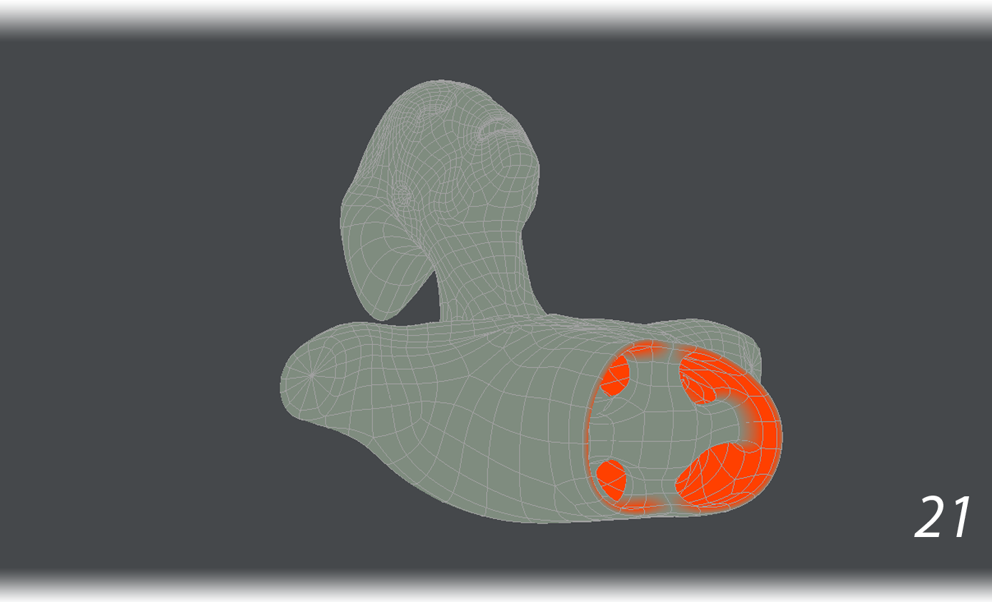
- We also created a weight map vmap called “Thickened” to mark the inner wall geometry with values of 100%. This weight map would be later used to invert the ZBrush displacement on the inside of the mesh (21).
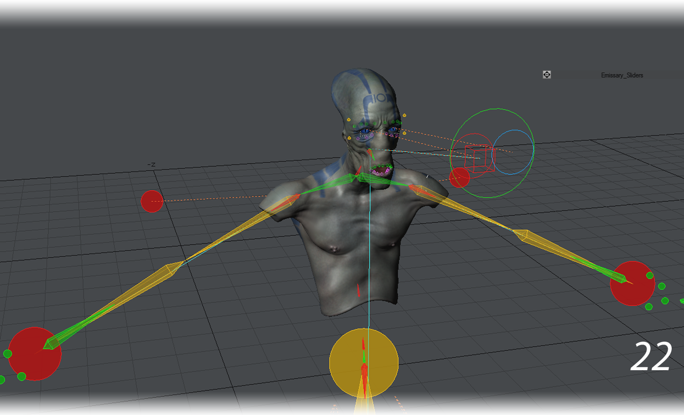
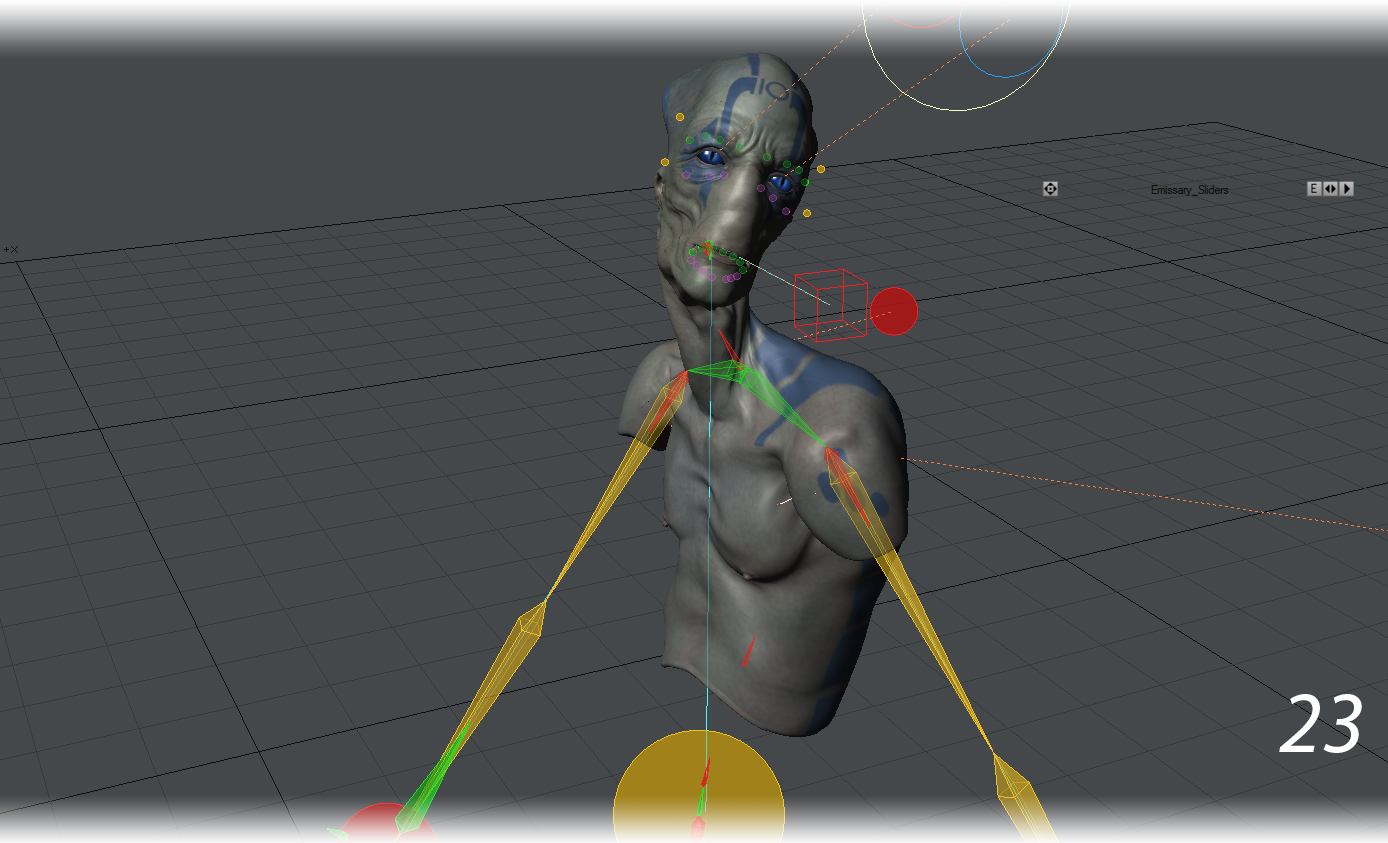
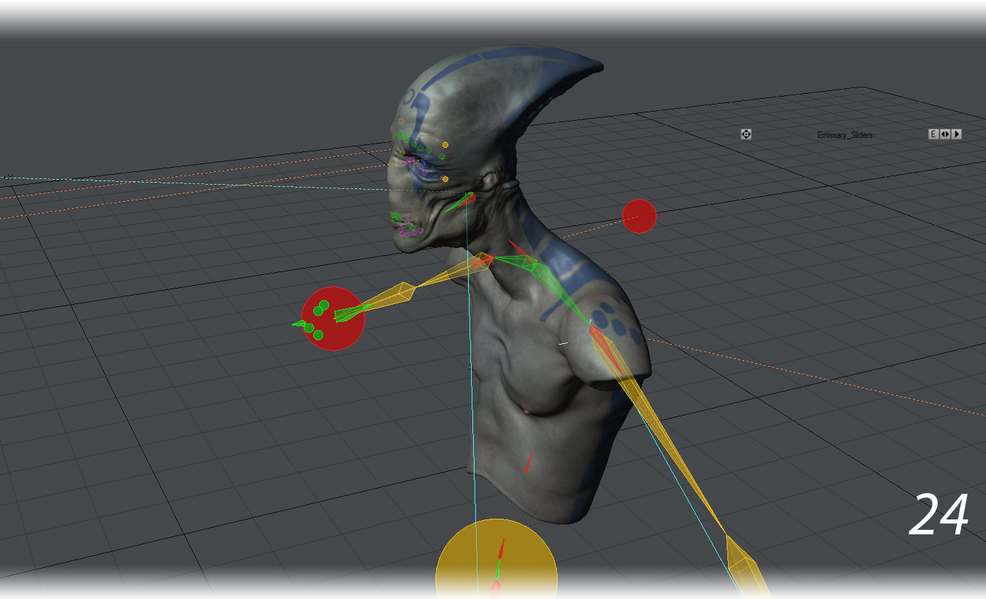
- Because the mesh matched that of the original alien, the original rig in Layout could have its mesh swapped out for the bust mesh. The alien could then be posed in Layout instead of Modeler. One advantage of posing in Layout is that many poses can be tried in one scene by keying different poses on different frames. (22-24) Morph Mixer was used to close the mouth.
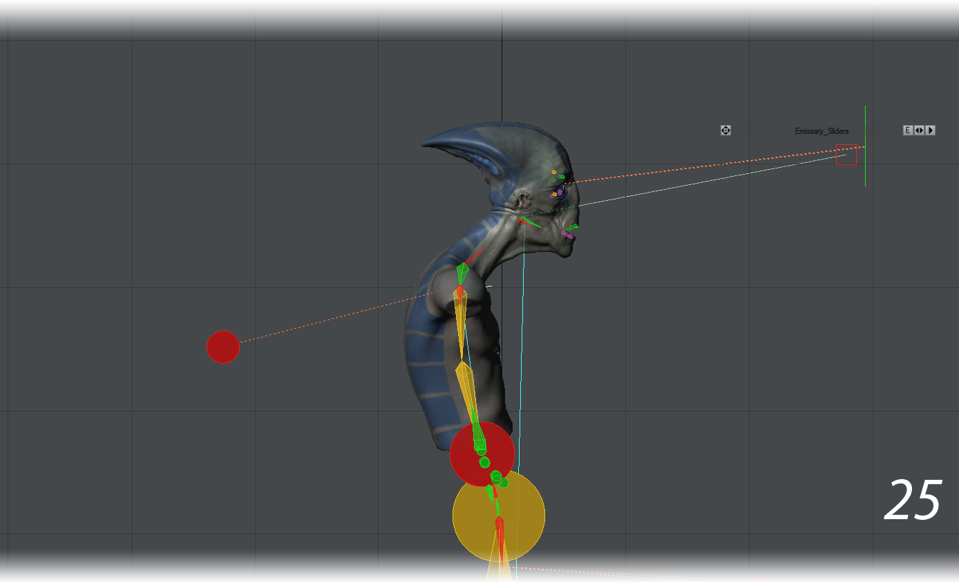
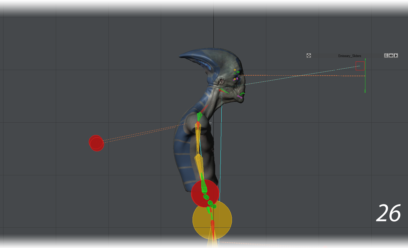
The final pose chosen was not too different from the original pose. The mouth was closed and the head raised slightly (25-26).
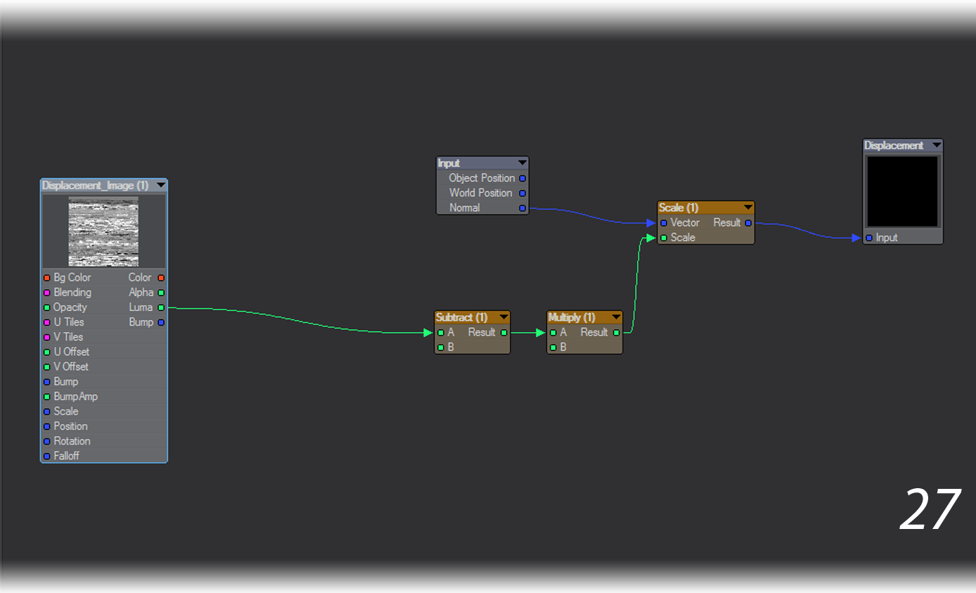
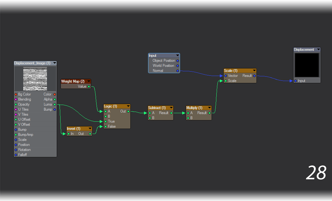
- The original node network in the Displacement Node Editor was modified to invert the ZBrush displacement on the interior geometry. That way, if the displacement map made an indent on the outer wall, the same spot on the inner wall would be raised instead of similarly indented. This helped preserve the wall thickness (27-28).
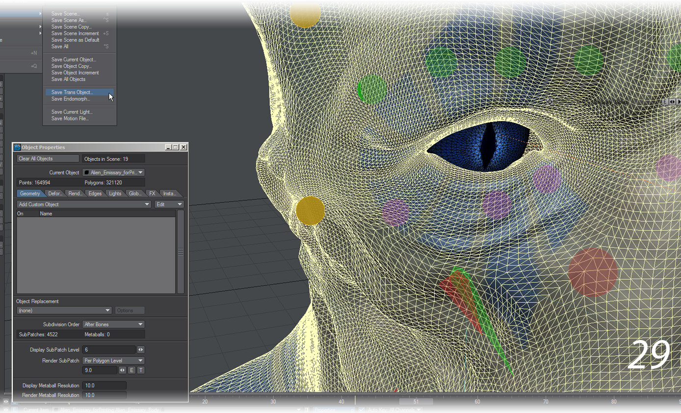
- When saving a subpatch object, Save Transformed respects the Subpatch Display Level . If the Subpatch Display Level is set to 0, Save Transformed will save out a subpatch model. If the Subpatch Display Level is set to 1 or higher, Save Transformed will save out a frozen, tripled mesh of polygons. The higher the Subpatch Display Level, the higher the number of polygons.
We set the Display Subpatch Level to 6, which meant that the bust (not including the pedestal or the eyes) would have 321,120 polygons when frozen. The more polygons used to describe details, the smoother the 3D print would be. We then used Save Transformed to save out a copy of the mesh in its posed, frozen position (29). A different filename was used for this copy so as not to overwrite the original subpatch object.
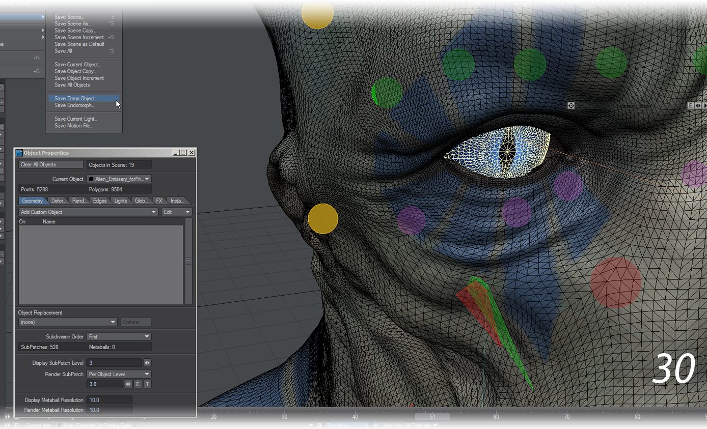
Although the exported mesh contained the bust geometry, it did not include the eyes. We selected the eyes object, set the Display Subpatch Level to 3 and used Save Transformed to export a frozen copy of the eyes in the same posed position as the bust (30).
- We now had two objects representing the posed and frozen geometry of the bust and eyes, respectively. These objects were brought into Modeler and placed into a single layer.
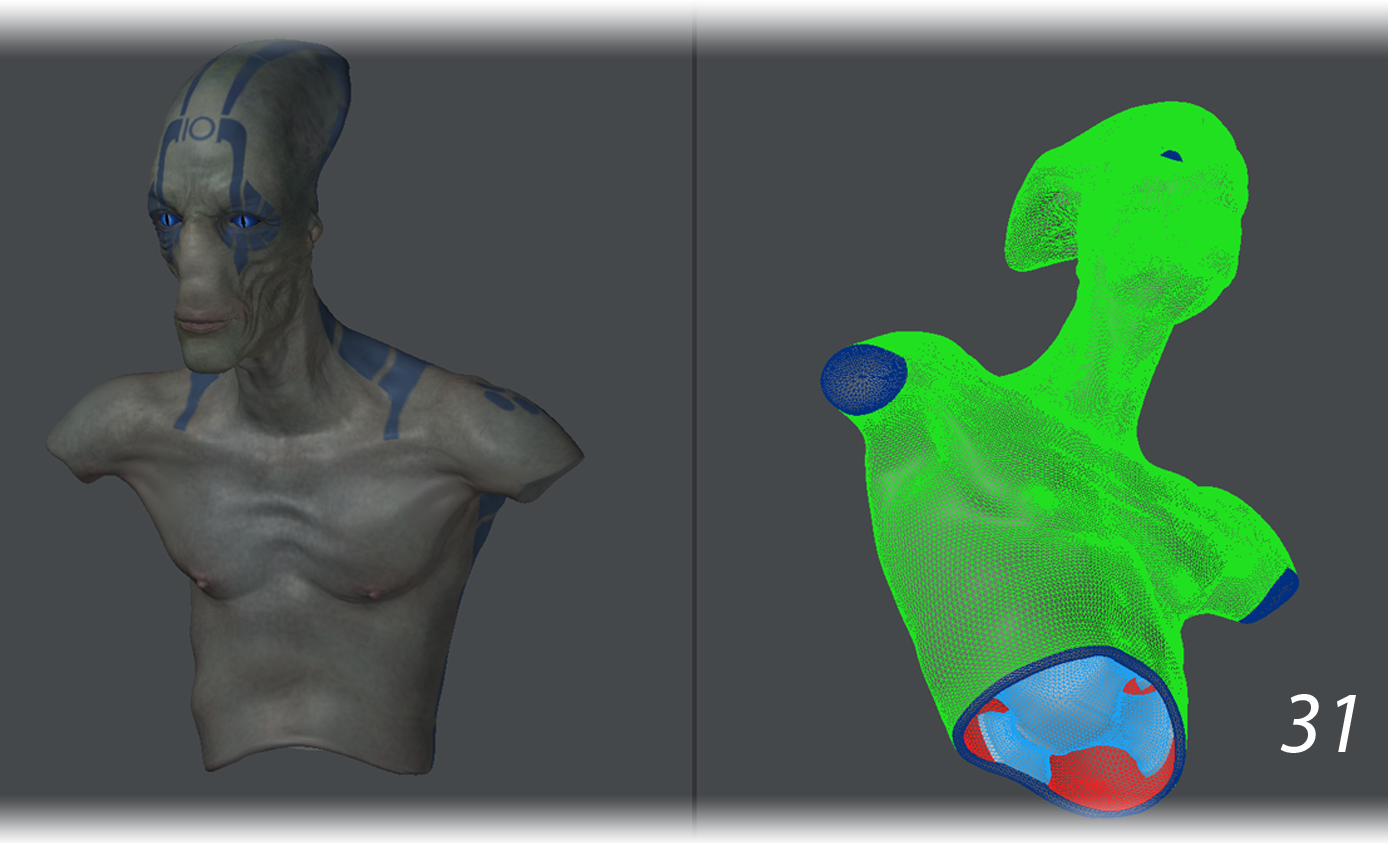
As spheres, the eyes did not need any special treatment. However, the bust needed one last inspection to make sure that its ZBrush displacement did not cause any intersection errors between the exterior of the skin and the interior of the skin. Making sure that the interior had a different wireframe color than the exterior of the geometry was about to pay off (31).
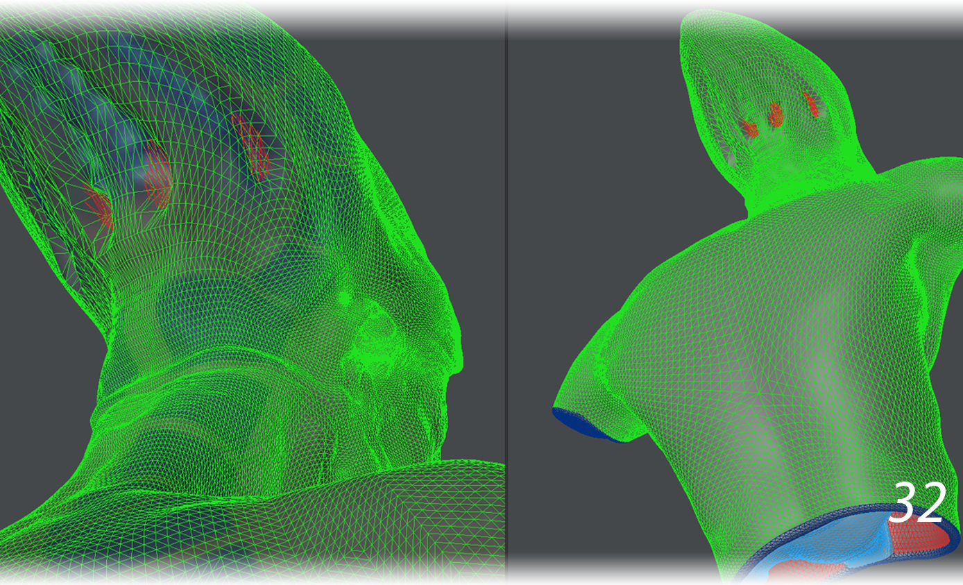
- Spinning the model around revealed an intersection between the interior and exterior geometry of the head in the rear (32). This intersection had to be resolved to ensure a good quality print.
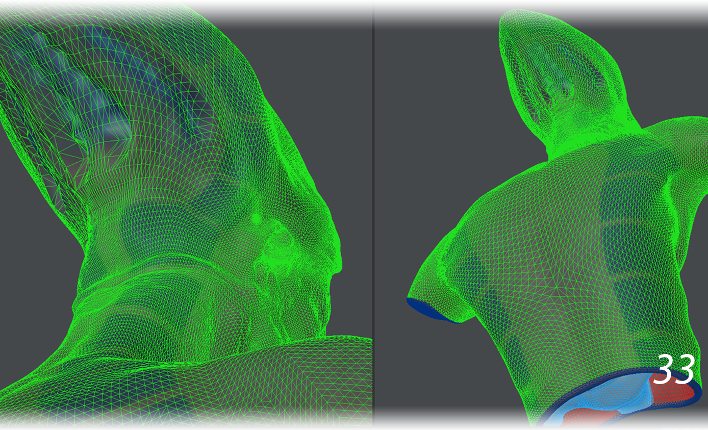
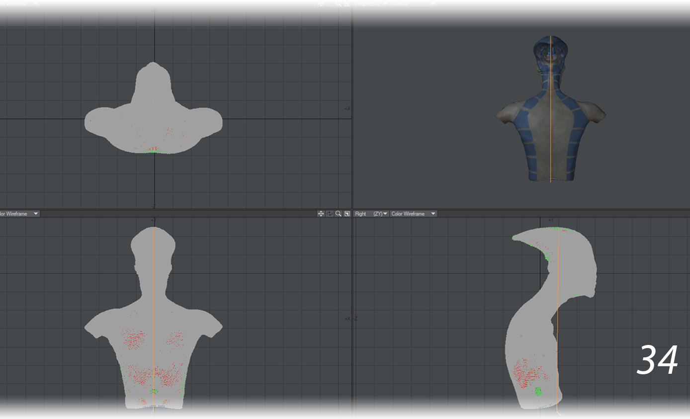
Selecting the offending geometry and using a combination of Magnet and Dragnet to push the geometry back into the skull fixed the problem (33). - At this point, the bust had a pose and good geometry. Now it needed to be scaled to print size. Scale was used to bring this mesh down to 25% of its original size. It was now about 200 mm in height (34).
- It could be printed, but it would not stand up on its own. This bust still needed a pedestal to support it after printing. Like the bust, the pedestal required high enough resolution not to appear faceted and a minimum thickness of 2 mm in order to be printable. It also required UV mapping for any texture maps.
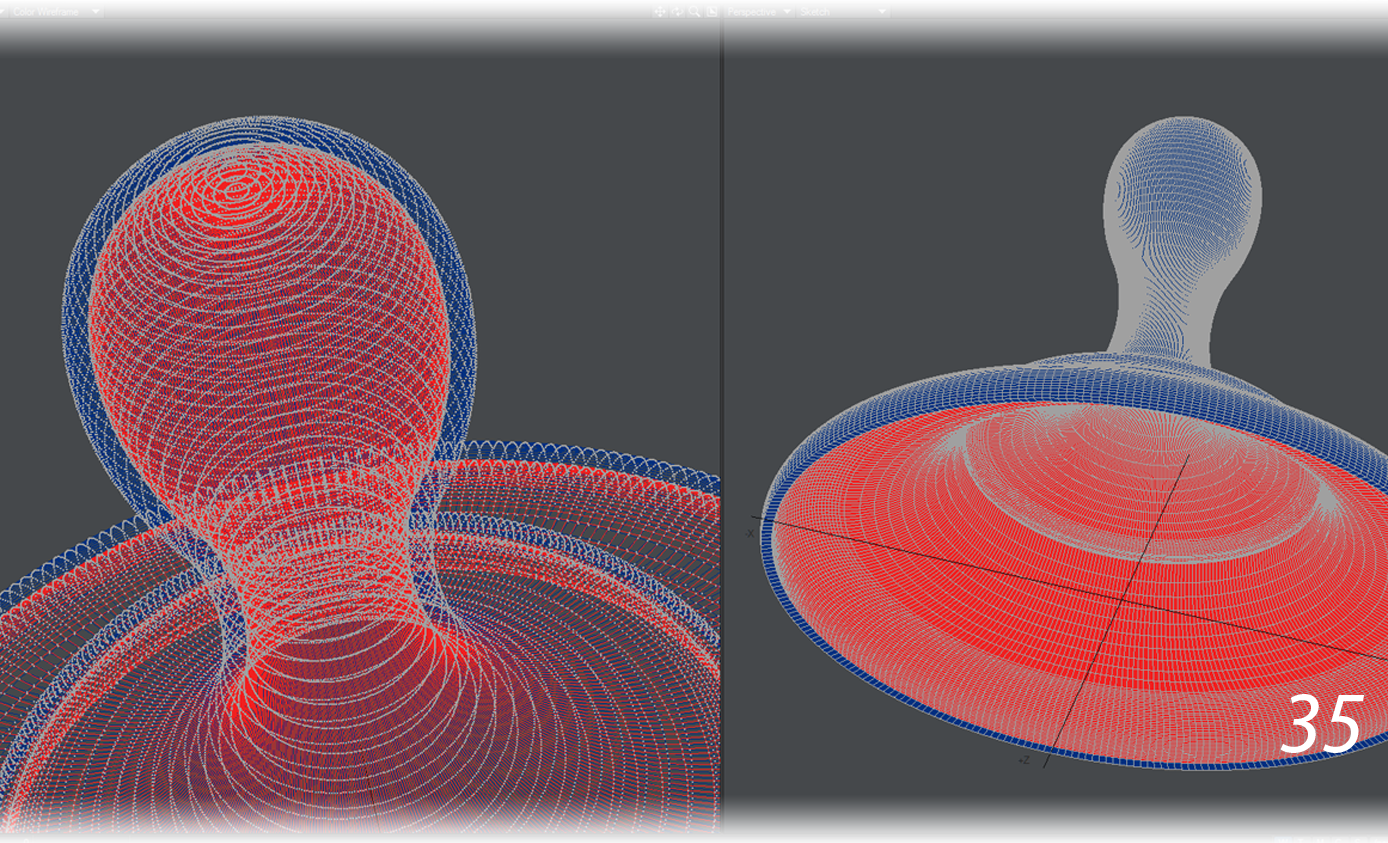
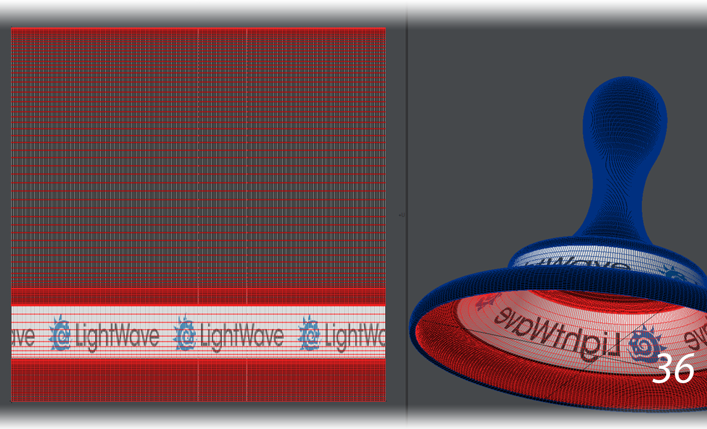
The pedestal was built to scale, using Lathe on a spline to create the shell of the pedestal (35) and mapping it with cylindrical UVs (36). We then used Thicken to give it a minimum wall thickness of 2 mm, and (as before) gave the Thickened surface a different wireframe color. Color Wireframe and Textured Wire display modes were used to detect any intersecting geometry, and the inner geometry was cleaned up by deleting unecessary loops with the Edit Edges tool.
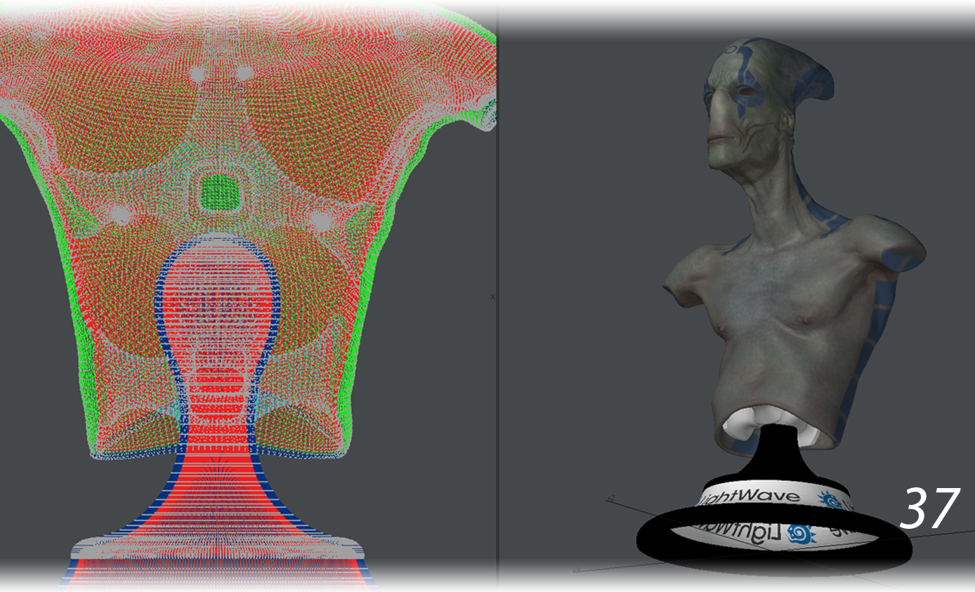
- A 3D printer can handle intersecting geometry up to a point. We took advantage of this and “attached” the pedestal with intersecting geometry. We lowered the bust onto the pedestal until the support structure within the bust intersected the top of the pedestal. There was no Boolean involved, just the intersection of two separate meshes (37).
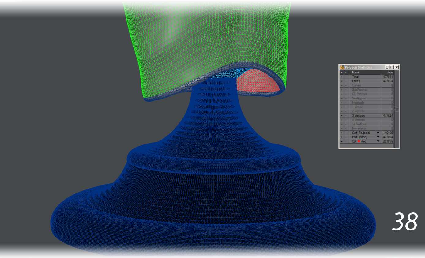
- The bust now had a pedestal. It now needed to meet Shapeways standards. All polygons need to be planar for 3D printing. The bust was already made up entirely of triangles. As a precaution, we tripled the mesh of the pedestal (38).
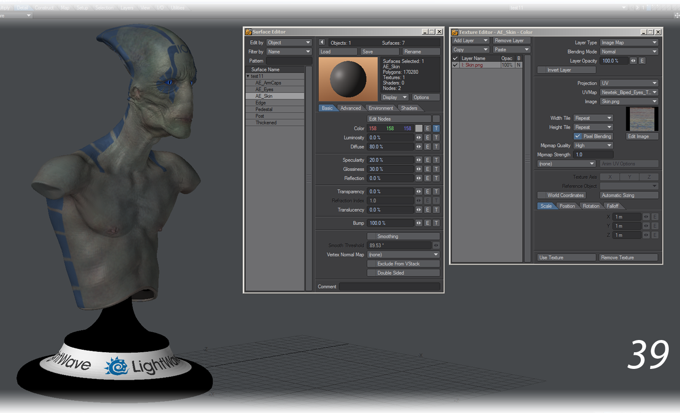
- Shapeways accepts GIF, JPG and PNG files for texture maps. GIF images are restricted to 256 colors, while the lossy nature of JPG files can result in compression artifacts. We opted to convert all of the original color TIF image maps to PNG files and save the model using them instead of the TIFs. For the statue’s surfacing, all non-color maps were removed, since the 3D printer was only concerned with geometry and color data (39).
- LightWave’s VRML exporter will export the first layer of the object, so we pasted the pedestal geometry, the bust and eye geometry into the first layer of the object. This was then exported as a *.wrl file using the VRML exporter.
- Lastly, Shapeways expects a ZIP file that contains only the *.wrl and associated texture maps in PNG, JPG or GIF format. This ZIP file cannot contain any folder structure whatsoever. Only files can exist inside this ZIP file. Shapeways is also case-sensitive, so the texture maps should have the exact same capital and lower case letters as the original texture maps.
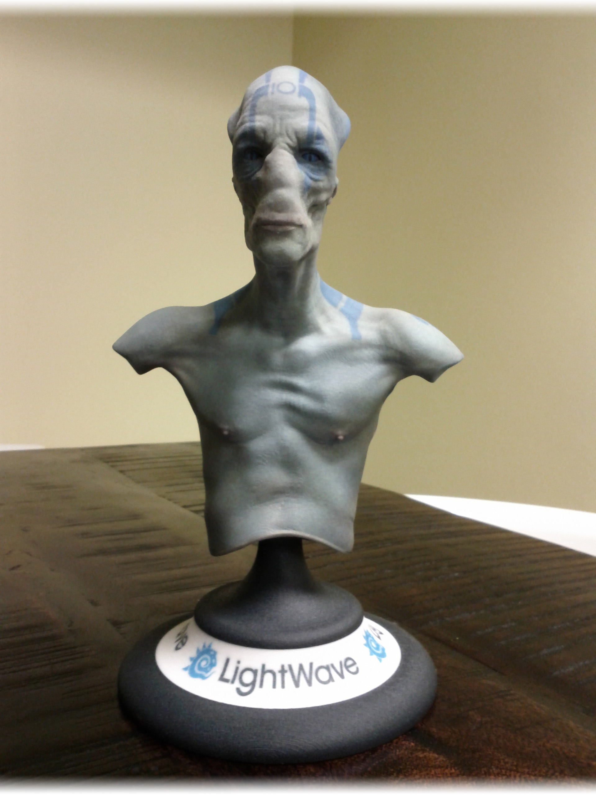
The end result surveys our office
For 3D printing there is no polygon budget and there are no tricks like smoothing or normal mapping. Your geometry needs to capture all the detail of your model; you are not going to use it for animating with.