Cloth Dynamics
Cloth Dynamics (ClothFX) have a variety of uses for supplying physical characteristics and natural movement simulation to thin, flexible materials.
Examples:
- Clothing on a character such as a dress or shirt
- Flag blowing in the wind
- Curtains
- Tablecloth or anything that needs to be draped over another object
- Mud flaps on a truck
- Hair
ClothFX Menu Tabs, Basic Tab menu
Cloth Dynamics are located in the Dynamics Tab of the Object Properties Panel. Choose Cloth from the Add Dynamic drop down list and then follow that by clicking on ClothFX in the Dynamics list window to open up the ClothFX options.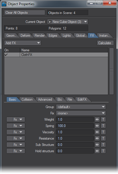
“Sew” function in use
Basic Tab
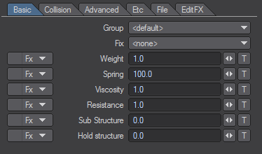
Basic Tab menu
- Group - you can group Dynamic objects with a user-defined name to prevent unwanted interaction. This also works with ParticleFX controllers. This becomes very handy when you are working on a complex scene and you want certain Wind emitters to affect only certain objects.
- Fix - The shape of polygons with “Fix” on remains intact and is not affected by the dynamics. In the image below, the ends of the cloth have been Fixed so that they stay in place while the rest of the geometry is pulled down by gravity.
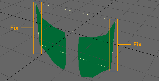
“Fix” applied to polygons indicated inside orange outlines – these stay in place, while gravity affects the rest of thecloth object.
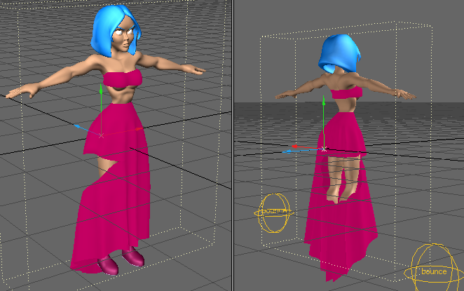
- Weight - defines the weight of the material. You can simulate the motions of a heavy material by increasing the Weight value, and you can simulate the motions of a light material by decreasing Weight.
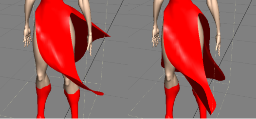
The dress on the right hangs down more due to its weight and also will not flap as much.
- Spring - controls the springiness or stiffness of the material. Reducing the Spring coefficient creates soft motions, while raising Spring produces motions with a stronger repelling force. Setting the coefficient to an extremely large value creates stiff motions.
- Viscosity - controls the level of impact that a collision will have on the shape of an object. An object with higher Viscosity value tends to keep its shape more. If an object bounces, a higher Viscosity value will have less bounce motion because the Viscosity absorbs the bouncing force.
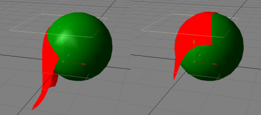
The pieces of cloth below are the same except for the Viscosity parameter. Here, a ball is moving up, pushing the piece of a cloth. The cloth with the higher Viscosity value tends to keep its shape more.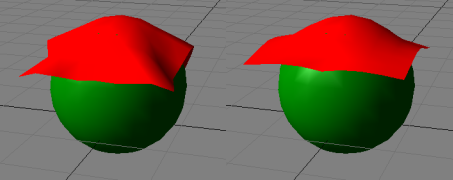
Effect of viscosity parameter on cloth. Left = lower viscosity, Right = higher viscosity
- Resistance - This parameter is not a characteristic of the object itself, even though it can be set per object. Resistance controls the amount of resistance of the environmental medium in which the simulation is taking place. For example, this affects how quickly a cloth object moves through the virtual air in the scene by determining how “thick” the virtual air is. The default setting is 1.0; raising this number increases the resistance and lowering to a number between 1.0 and 0.0 decreases the resistance. This allows the simulation of a wide range of gaseous or even liquid media as the environment for the physical simulation. A negative number amplifies a collision of the cloth object. To simulate behavior within a normal atmosphere at sea level, a value of .14 would be appropriate. A value of 1.0 gives the medium a character close to that of molasses.
If you are coming to LightWave from Maya, the function that is most similar from that application is “Damping.”
- Sub-Structure - The surface of a pure, elastic body model has a high degree of freedom, which causes the object to easily distort. To prevent distortion, you can apply an auxiliary form, called a Sub-structure, to restrict the instability of the surface. This can improve your results with a two-dimensional object (i.e., one with no thickness) making it act as if it has some thickness. However, this reinforcement can require a high Sub-Structure setting that can take longer to calculate.
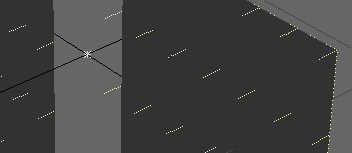
When Sub-Structure is used on a square mesh, it creates something that looks like two triangular polygons placed on top of each other in opposite directions. The Sub-structure mitigates the tendencies to bend and to resist bending in certain directions.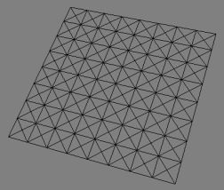
Substructure applied to the quadrangles of a mesh.
When the Sub-structure value is non-zero, the auxiliary form is applied. The higher the value, the more the form will have a tendency to keep its shape.
- Hold-Structure - because a pure elastic body model simulates only the surface structure, it is limited to two-dimensional motions, such as a bed sheet. In order to simulate elastic three-dimensional motions, such as a lump of gelatin, a Hold-structure needs to be used. This parameter causes a surface to tend to maintain its original shape, like gelatin does when it jiggles.
The effect of Hold-structure is uniform throughout the surface, while with Sub-structure it is non-linear, which will often result in a more natural look. You can use a combination of both to achieve just the right result.
- FX Button - Allows you to use a Vertex Map to control the value of an attribute (spring, viscosity, etc.) or a function (delay, wave size, compress bump).
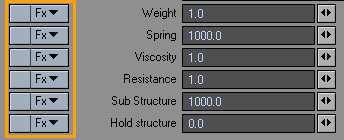
FX Drop Down menu buttons
From the FX drop down menu the user can select a Vertex Map as well as change the base value. - Vertex Map – Will be displayed by name and type.
Example: “LeftArm/Weightmap”
- Weight Map – The weight value of each point is defined in Modeler when you create a Weight Map. In Layout you cannot edit Vertex Map values. But the FX button allows you to add a modifier that, when combined with the original values of the Vertex Map, provides a way to adjust the values of the selected attribute/function without changing the original Vertex Map value.
- Pointset – A pointset is created in Modeler. In Layout you cannot add or subtract points from a pointset. But the FX button allows you to add a modifier that, when combined with the pointset (value of 100%), provides a way to adjust values of the selected attribute/function.
- Surface – Surfaces are created in Modeler. In Layout you cannot add or subtract points from a surface. But the FX button allows you to add a modifier that, when combined with the surface (value of 100%), provides a way to adjust values of the selected attribute/function.
- UV – UV maps are created in Modeler. In Layout you cannot add or subtract points from a UV. But the FX button allows you to add a modifier that, when combined with the UVs value, provides a way to adjust values of the selected attribute/function.
You can always check value information for points in the Point Info windows.
- Base – Selecting the <base = 0> option from the FX Drop Down menu will open a small requester that allows the user to edit the base value. Changing the base value changes the effective range. Example: Base=0% (0 – 100), Base=20% ( 20 – 100). The base value is 0% by default.
For those interested, the equation used to calculate the vertex point value is: Vp = Vmap * value+ (1- Vmap) * base. Another way to look at the equation is: Vp=(value-base)*Vmap+base.
Collision Tab
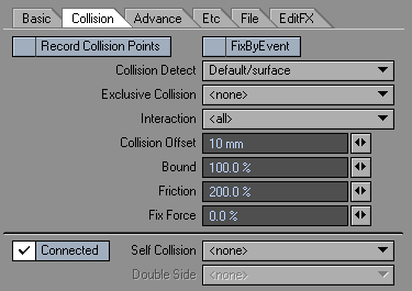
- Record Collision Points - When this is activated, ClothFX will record the time and location of a collision, which will trigger a particle emitter that has been set up and that is parented to the ClothFX object.
Record CP works with ParticleFX and Nozzle=Parent collision, but you cannot use it with FX Collision and Parent Recorded CP (FX emitter>playback mode).
- Fix By Event - This function will fix points that pass through a collision object that is set to “Event” mode.
- Collision Detect - allows other objects to influence the motion of a dynamic object. This lets you create complex motions caused by obstacles in the path of the dynamic object. The simulation is performed by taking an object that collides (the collision object) with the elastic body model (dynamic object) into account in the calculation.
- Exclusive Collision - When a collision object is selected from the list in this control parameter, it becomes the sole collision object. All other collision objects are excluded from the calculation.
- Interaction - By Default you would want Interaction set to “All” so that all geometry will interact with each other. However you have the option of limiting the interaction by Vertex Maps.
- Collision Offset - By default the collision offset is set to 0 so that the collision object will collide with the surface of the target object, allowing the target object to deform. Increasing the Collision Offset will result in the collision object deforming the target object at the distance specified in the Collision Offset field.
Collision offset
You should understand that the collision is detected using a point on the target object (elastic body model) and a polygon of the collision object. As a result, a polygon of the target object can possibly penetrate the collision object—usually an undesirable result. Use the Collision Offset setting to avoid undesired surface penetration.
- Bound - adds a rebounding speed change at collision.
- Friction - Like real-world friction, the Friction parameter makes the surface of the dynamic object less slippery. So, if you want the Dynamic object to tend to slip off the collision object, set Friction to 0. If you want it to stick more, increase the value.
The settings on the right image have a higher friction causing the cloth to stick to the collision object.
- Fix Force - causes the dynamic object to stick to the surface and not slide around.
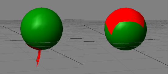
The image on the right has a higher Fix Force setting.
- Self Collision - The Self Collision setting helps prevent a soft or cloth object’s mesh from passing through itself when the object is transformed during the simulation. Self Collision is calculated based on a point on the target object and a polygon on the collision object. If a surface has Self Collision and Collision Detection active, Self Collision is computed on the same surface.
Self Collision works in much the same way Collision Detection does, and there is no collision detection for polygon edges. As such, you may also want to adjust Collision Offset to avoid errant point penetrations.
- Connected - Connected is a Self-Collision option that derives its name from the Select Connected option in Modeler. When activated, a contiguous mesh within an object can self-collide. When deactivated, adjacent meshes within a single object can “self-collide” with each other, but any given mesh will not be able to collide with itself.
An example would be a character object that has been modeled with a complete body mesh and with clothing as additional meshes that are not part of the body mesh, such as a T-shirt. The T-shirt and the body of the character would be separate contiguous meshes - that is, in Modeler, selecting a few polygons on the T-shirt and hitting Select Connected will select all of the polygons of the T-shirt, but not select the polygons of the body. Selecting a few polygons on the body and hitting Select Connected will select all of the polygons of the body, but not the T-shirt.
In ClothFX, if Self-Collision is on but Connected is de-activated, the T-shirt can collide with the body, but not with itself. If Connected is activated, the T-shirt can collide with itself and with the body of the character. Deactivating Connected, then, can speed up a self-collision calculation at the cost of accuracy. Use only when separate meshes contained within a single object layer must collide against each other, but do not have to collide with themselves. Do not deactivate this option when dealing with curtains, windsocks, or any other situation where the material must self-collide with areas actually connected to itself.
- Double Side - Collision is detected even if the motion is from behind the polygon.
Advanced Tab
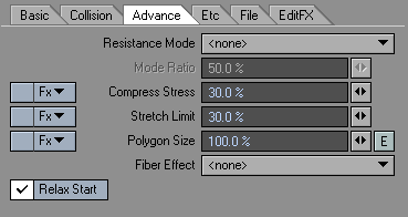
- Resistance Mode - Resistance mode tells the Resistance setting in Basic Tab how to react. With some amount of Resistance applied, you can see as you change Mode settings how the polygons will resist wind effects.
- None - points move based on wind direction.
- Polygon - points move based on wind direction + point normal.
- Polygon (front) - points facing the wind move based on wind direction + point normal.
- Polygon (back) - points facing away from wind move based on wind direction + point normal.
Resistance Mode settings only apply to wind.
- Mode Ratio - sets the amount of Resistance applied to specific effects set by Resistance Mode versus standard. 75% sets 75% of the Resistance Mode and 25% of the standard resistance.
Compress Stress- controls the amount of compression a surface exhibits as a result of stress. A soft fabric like cotton can be made using a large Spring value and a low Compress Stress setting.
A stiffer fabric would use a higher Compress Stress setting. An example for use: you could easily make the apparent thickness of drapery vary with this setting.
Compress Stress affects the strength of Spring and Substructure spring forces when they become compressed during the calculation. Suppose a polygonal edge, which represents a Spring force, is 1m in length, and the Spring strength is set to 1000 and the Compress Stress to 30%. If the material is stretched so that the edge becomes more than 1m in length, the Spring force will snap back with its full force of 1000. If the material is compressed so that the edge becomes less than 1m in length, the Spring force will push the points back with a force of only 300 (30% of 1000). The same Compress Stress percentage applies to Sub Structure forces when a Sub Structure spring is compressed below its original length.
- Stretch Limit - To prevent a surface from stretching like rubber, lower the Stretch-limit below the default value of 100%. This restricts the amount that the surface can be stretched. Setting Stretch Limit to 0% turns it off completely. For free-moving cloth like flags and curtains, one might set it as low as 1%. However, give clothing some “breathing room” in the Stretch Limit, and do not lower it below 10% for clothing items like sleeves, shirts, and pants. To reduce sagging in clothing, reduce the Polygon Size, not the Stretch Limit.
Although you could also increase the Spring value to reduce stretching, increasing that value can make the behavior of the surface too complex and cause problems such as weird folds.
- Polygon Size - Changes the surface to a specified size. For example, a value of 90% reduces the size of the surface to 90%. Use Polygon Size to reduce the looseness of a dress or to create frills.
- Fiber effect - Allows you to set an axis for the traditional Fiber effect, basically making a certain axis “stronger” than the others. For example, setting Y as the axis makes the built-in folds of the dress (dress_fx002) stronger so the folds aren’t disregarded during calculation.
- Relax Start - When this option is on, the ClothFX object starts out with no “Stress State”, meaning that the object is considered to be in its “true” or “base” state. Thus, if any displacements are applied to the object on the first frame of the calculation, the resulting form will be considered the “true” or “base” form of the object. This includes any Stretch/Size, bones, displacement maps, or morphs present on the first frame of the calculation. ClothFX will respect the size of each polygonal edge as the “true” length of each polygonal edge, and it will stick close to the distorted proportions of the object during the calculation.
When Relax Start is turned off, ClothFX considers the undistorted state of the object as it would be seen in Modeler to be the “true” or “base” state of the object. If the object is deformed by Stretch/Size, bones, displacement maps, or morphs on the first frame of the calculation, the object is considered to be “stressed” and will regain its “true” proportions during the calculation.
For example, take a sheet of polygons aligned with the XY plane and fix the uppermost row of points. If this object is stretched to a value of 4 on the Y axis, and Relax Start is turned ON, then the stretched version is accepted as the “true” version, and the calculation will be for a tall version of the object, without any great fuss. If Relax Start is turned OFF, then the unstretched version is regarded as the “true” form of the object. Because the object is stretched to four times its original size on the first frame of the calculation, the effect is as though the object begins by being stretched like a rubber band. As soon as you hit Calculate, the non-fixed points of this non-relaxed object will SNAP back into distances between themselves and their neighbors that more closely resemble the distances between them in the undistorted version of the object as would be seen in Modeler.
Etc. Tab
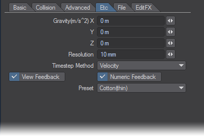
- Gravity(m/s^2) - Specify the direction and intensity of gravity along the world axes for this particular dynamic object. Note that when you set gravity in the Etc Tab for your dynamic object, it is not necessary to add a gravity controller separately. Conversely, if you add a gravity controller and set your gravity characteristics properly there, it will not be necessary to set gravity for the dynamic object on the Etc Tab. If you have a number of objects in the scene that you wish to have affected by gravity, then it might save effort to add a gravity controller and properly set it up and size it to affect all the necessary objects.
The gravitational acceleration constant on earth is 9.81m/s^2. On planets with a less strong gravitational pull, (such as the moon) it is much lower, whereas on planets with a stronger pull (such as Jupiter) it is much higher. In LightWave’s coordinate system, you would set gravity by entering a negative value in the Y entry field; -9.81 m for Earth-normal gravity.
- Resolution - Set the accuracy of calculation by how big the maximum error is.
When it approaches 0 the accuracy increases and errors will decrease, but calculation workload will also increase so it will take more time to calculate.
Timestamp Method was introduced to resolve an issue where ClothFX could get stuck doing very small timesteps in some cases. This would most often happen with meshes having vertices surrounded by tiny polygons. The default is “Velocity” which is the old method, and “Frequency” is the new method. “Frequency” does not always work, so if one doesn’t work try the other.
- View Feedback - Set the feedback in Layout when controlling ClothFX. When the display is poor or the display speed is slow, you uncheck this.
- Numeric Feedback - Set the numerical feedback in Layout when controlling ClothFX . When the display is poor or the display speed is slow, you uncheck this.
- Presets - Similar to surface presets, ClothFX has 5 built in presets that give you a good place to start. Presets include: Cotton Thin, Cotton Thick, Silk, Rubber, Jelly.
File Tab
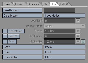
Figure 18: File Tab
- Load Motion - Loads a previously generated Motion file.
- Clear Motion - Clears a loaded Motion file.
- Save Motion - saves the generated motion to a file, which will be used subsequently to deform the object.
After a motion file is saved, the name of the file will automatically be entered into the load field.
Load Limit- Loads a limited range of Frames. Example: If you have a MDD file with 2000 frames of data you can limit loading to just 100 frames to make it less memory and processor intensive.
Playback Mode
- Normal - Plays back all Motion settings of the .mdd file.
- Local - Plays back based on the local translations (move, rotate and scale) of the object. Allows a .mdd deformation on an object while respecting new motion applied to that object.
- Distance Map - This adjusts the motion data to the movement of the object. When the speed is 100%, 1s (second) of motion data is used to move the object a distance of 1m.
- Speed - When Playback Mode is set to Local or Distant the user is able to control the playback speed. One can also play the MDD file backwards from by setting Speed to –100% and inputting the frame-length of the MDD file into Shift Frames. For example, if the user recorded a 300-frame MDD file, he could play it backwards by setting the Playback Mode to Local, the Speed to –100% and the Shift Frames value to 300
- Node Match - When Node Match is activated, the motion data can be played back on the object’s local position. Node Match allows one to play back MDD data recorded from an object with a different point count and order as long as the points share the exact same XYZ coordinates in Modeler. For example, suppose you had a castle model with a flag on top. One could run ClothFX on the whole castle, but this would result in a large MDD file for such a tiny detail, the flag. So, in Modeler, delete the castle polys and save the flag as a different object. Record the ClothFX calculations on the flag, and save the MDD file. Load the castle into Layout, apply ClothFX, load the MDD file calculated from the flag, set the playback to “Local” and activate Node Match. Node Match will remap the MDD data recorded from the flag-only object to the XYZ equivalents on the castle-with-flag geometry
- Shift Frames - The user can shift the time the motion starts. Use Shift Frames if you need the motion to start on an earlier or later frame. By default, the number entered is regarded as a number of seconds to shift the .mdd file. If you prefer to use frames, enter the number of frames followed by the letter “f”; “-400f”, for example, to shift so that the motion in the .mdd file starts at frame -400.
- Loop - The user has the option to loop the motion file in two ways.
- Repeat - Plays the motion from start to finish and then repeats the motion from start to finish continually.
- Oscillate -Plays the Motion from start to finish and then plays it from the end frame backwards to the start frame and then repeats the cycle. (Ping Pong motion)
- Motion Size - Motion Size increases the distance relationship between points in a motion file.
- Copy - Use the Copy button to copy the current settings between dynamic objects.
- Paste - Use the Paste button to paste the current settings between dynamic objects.
- Save - Saves all the settings contained in the ClothFX properties.
- Load - Loads a saved Settings file. This is similar to using a Preset.
- Scan Motion - Scans the motion of the object and applies the scanned results (.mdd file) to the object.
This means you don’t have to apply another plug-in to scan the motion (including bones, etc). It eliminates the steps of loading the motion file back in, and also enables you to quickly scan an object’s motion to allow for the use of EditFX on an object even if it’s not using dynamics.Info- Clicking the Info button brings up a window that gives you the version # of ClothFX and the MDD file information.
EditFX Tab
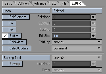
- EditTool - Activates the ability to edit points. You will be able to visually see that you’re in Edit Mode in the viewport. All the points that make up the object will become highlighted and all the EditTool functions will become active.
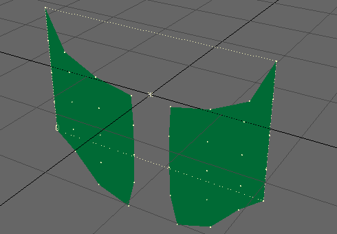
Sew function applied
- Undo - The EditTool has its own undo. Click this button to undo the last edit that was made. You can only undo one edit.
- EditNode - Specify the ID number of the point to be edited. If the EditTool is activated, you can select the target point from the Layout viewports by clicking on the point.
- EditFrame - There are 4 modes to edit the Node’s (point) motion path.
- All - will edit the entire Motion Path .
- After - will edit the current frame and everything after it.
- Before - will edit the current Frame and everything before it.
- Current - will edit only the current Frame.
- EditStart / EditEnd - Use the EditStart and EditEnd Fix options to set the range of frames that the user will be able to edit. All other frames will be fixed (locked).
- EditSize - (Edit Range) This field changes the influence range.
- Edit Falloff - This drop down is located to the left of EditSize. This will change the Falloff settings to either None, Soft, Linear, or Hard. As shown in Figure 19, by default the setting is Soft.
- None - All vertices are influenced; in other words the whole mesh moves.
- Linear - Deformation in the range of EditSize is attenuated linearly.
- Soft - Deformation is attenuated smoothly in the range of EditSize.
- Hard - Deformation occurs uniformly in the range of EditSize, and is not attenuated.
- EditAxis - This sets the axis/axes in which the Node (point) can be edited. (All, X, Y, or Z)
You do not have to re-calculate when you move the path or keyframe data with EditAxis.
- EditMap - This option lets you limit the portion of the object that is editable by giving the user the option to edit by Vertex Maps.
- SelectUpdate - When activated, you can re-calculate only the parts selected by EditNode. To re-calculate, click Calculate with SelectUpdate checked.
- Command - The Command drop-down offers two commands for use during the editing process, Smooth and Makepath.
- Smooth - Referring to the current frame, the movement of the parts that were selected by EditNode will be smoothed. When EditStart and EditEnd are not specified, the movement of the selected parts to the current position will be smoothed across all the frames. When EditStart and EditEnd are specified, it will make the position information smooth from the specified frames to the current frame.
- Makepath -This command will create a Null object whose path is identical to the motion path of the selected part.
- Sewing Tool - Enables Sewing Mode. Sewing Mode gives the user the ability to sew Nodes (points) together.
- Sewing - This button is the third step in a three-step process of sewing Nodes together using the Sewing tool.
Steps to Sewing: “Left Click” on the first point and “Right Click” on the second point. Then click on the Sewing button.
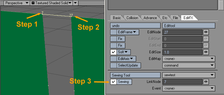
- Current Sew Object - Drop down list located to the right of the Sewing tool enables the user to choose which object is being sewn.
- Link Node - Displays the Node that has been selected.
- Event - This drop down menu determines whether the linked nodes will be Cut by an event or sewn by an event.
- Cut by Event - When an Event object passes through the Nodes (points), they will break apart and become separated.
- Sew by Event - When an Event object passes through the Nodes (points) they will be sewn together (Merged).