Container Panel
Menus
There are several menus, and panels inside of menus, in TurbulenceFD. It is important to understand not only what they do but their relationships to each other. Below is a breakdown of each menu type and its basic purpose. Each menu button will bring up their respective menu panels. Let's go through these below.
Containers
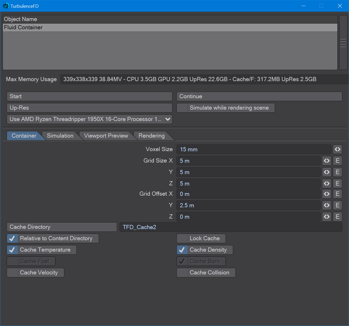
Opens the container control window that holds the list of fluid containers, the Container Parameters and the simulation controls. The container parameters are:
Max Memory Usage: - This field shows the maximum resolution (in voxels) that the container can use as well as the amounts of memory that it would use in this case. How much the simulation will actually need depends on how the simulation grows over time.
Here is an example:
386x649x395 99.0MV - CPU 7.9GB GPU 3.7GB UpRes 62.4GB - Cache/F: 1.9GB UpRes 14.9GBThe first section shows the maximum dimensions of the container in voxels and the total number of MegaVoxels or Million Voxels (MV).
The middle section shows the amount of memory the simulation will at most require when run on the CPU, the GPU or in Up-Res mode.
The last section shows the maximum size a single cache frame would have on disk without compression for a normal simulation and an Up-Res pass.
When starting the simulation, TurbulenceFD will warn you if the available memory would not suffice would the simulation take up the whole container. You can ignore the warning if you know that your simulation will stay small enough or if you're keeping an eye on the simulation progress, so you can abort the simulation if necessary. When running simulations un-supervised, it's a good idea to make sure the container dimensions and simulation settings are chosen such that the available memory is sufficient.
If the available memory is exceeded, the machine will most likely become unresponsive and you may have to reboot your system.
Start - Simulate the fluids in this container from the beginning of the selected frame range (see Simulation/Timing/Frame Range).
Continue - Continues a simulation after the last simulation state. This last state is always saved when the simulation stops - either because you clicked the Stop button or because all frames from the selected range have been simulated. This also allows you to add more frames at the end of the range.
Up-Res - Post-processes a simulation to increase the resolution and add more detail. A new cache directory will be created using the name of the current cache with the word "upres" appended. You can switch back to the previous cache using the Container/Cache Directory button. See the Simulation/Up-Res tab for more options. This post-process is faster than simulating at a high resolution in the first place. It will also retain the shape of the lores simulation and only add small details that couldn't be resolved on the lores grid before.
Simulate while rendering scene - If checked, the simulation will be run as needed while rendering the scene. This is somewhat faster than simulating and rendering in two passes since the caches don't have to be loaded from disk. With lores camera settings, this is also useful as a previewing mechanism while working on the simulation.
Use CPUs/GPU - If you have supported GPUs, this drop-down list will let you select which one to use. See GPU Simulation for more details about fluid simulation on GPUs. If "Use CPUs" is selected, all available CPU cores will be used instead.
GPU simulation
Fluid Simulation needs quite a bit of processing power. Mostly because there is a huge amount of data to be pushed around. This makes memory bandwidth the most important factor for simulation speed. Today's fastest memory interfaces are found in GPUs - about 10 times faster than those of CPUs. Coupled with the appropriate amount of parallel computing power, GPUs are the ideal type of processor for fluid simulation.
TurbulenceFD makes use of GPUs for its simulation pipeline. Unlike some GPU-accelerated tools, this is not just a stripped-down version of the CPU pipeline. All features are supported at the same quality. In fact, you can switch between CPU and GPU simulation on the fly (see Simulation Window). This is also what TurbulenceFD will do automatically, should it run out of GPU memory. It will then continue the simulation on the CPU. Supported GPUs
At this time, TurbulenceFD only supports Nvidia GPUs with Compute Capability 2.0 or newer, listed at http://developer.nvidia.com/cuda-gpus
While TurbulenceFD technically works with less than 1GB of GPU memory, a GPU with 4GB or more memory is highly recommended.
Please make sure to use the latest driver for your graphics card and if possible, make use of the Studio edition drivers as they are typically much more stable than Game edition releases.
For the purposes of this documentation and our demonstration content, assume that you will need at least a nVidia GTX 1070 or above graphics card with 8GB (minimum) of VRAM in most cases, in order to simulate them without running into a limited VRAM situation.
Hardware Setup Tips
At this time, TurbulenceFD can only make use of one GPU per simulation container in a scene. While it is possible to have different GPUs assigned to different containers, only one container can be simulated at a time.
When choosing a GPU, prefer the one with the most per-GPU memory (note that per-GPU memory for Dual-GPU boards is usually half of the advertised amount)
Even prefer a slower GPU if it has more memory than an alternative faster GPU (see this post for the rationale behind this advice)
Ideally use two GPUs: one (possibly smaller one) as primary display GPU and one as a secondary GPU for simulation only.
When your system has only one GPU and you run large simulations, disable the viewport preview to speed up the simulation.
If you have a supported GPU but don't have anything to select but "Use CPUs", update your graphics display driver (see Supported GPUs above).
The larger the voxel size resolution the better the speedup (GPU vs. CPU) will be.
Tabs
Max Memory Usage This field shows the maximum resolution (in voxels) that the container can use as well as the amounts of memory that it would use in this case. How much the simulation will actually need depends on how the simulation grows over time.
Here is an example:
386x649x395 99.0MV - CPU 7.9GB GPU 3.7GB UpRes 62.4GB - Cache/F: 1.9GB UpRes 14.9GB
The first section shows the maximum dimensions of the container in voxels and the total number of MegaVoxels or Million Voxels (MV).
The middle section shows the amount of memory the simulation will at most require when run on the CPU, the GPU or in Up-Res mode.
The last section shows the maximum size a single cache frame would have on disk without compression for a normal simulation and an Up-Res pass.
When starting the simulation, TurbulenceFD will warn you if the available memory would not suffice would the simulation take up the whole container. You can ignore the warning if you know that your simulation will stay small enough or if you're keeping an eye on the simulation progress, so you can abort the simulation if necessary. When running simulations un-supervised, it's a good idea to make sure the container dimensions and simulation settings are chosen such that the available memory is sufficient.
If the available memory is exceeded, the machine will most likely become unresponsive, and you may have to reboot your system.
Start
Simulate the fluids in this container from the beginning of the selected frame range (see Simulation/Timing/Frame Range).
Continue
Continue a simulation after the last simulation state. This last state is always saved when the simulation stops. Be it because you click the Stop button or because all frames from the selected range have been simulated. Therefore, this also allows you to add more frames at the end of the range.
Up-Res
Post-process a simulation to increase the resolution and add more detail. A new cache directory will be created using the name of the current cache with the word "up-res" appended. You can switch back to the previous cache using the Container/Cache Directory button.
See the Simulation/Up-Res'ing tab for more options.
This post-process is faster than simulating at the high resolution in the first place. It will also retain the shape of the lowres simulation and only add small detail that couldn't be resolved on the lowres grid before.
Simulate while rendering scene
If checked, the simulation will be run as needed while rendering the scene. This is somewhat faster than simulating and rendering in two passes, since the caches don't have to be loaded from disk. With lowres camera settings, this is also useful as a previewing mechanism while working on the simulation.
Use CPUs/GPU
If you have supported GPUs, this drop-down box will let you select which one to use. See GPU Simulation for more details about fluid simulation on GPUs.
If "Use CPUs" is selected, all available CPU cores will be used instead. You cannot switch methods while simulating.
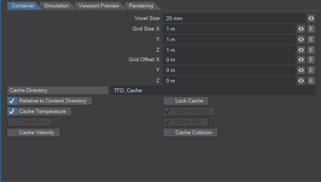
Voxel Size - Specifies the size of a voxel. Voxels are cubes. This value specifies their side length. When changing this value, the resolution will change accordingly.
Grid Size - This specifies the size of the fluid container. The simulation will clip everything outside of this box. In most cases, the simulation will clip even more than that, trying to minimize the box that actually needs to be simulated. See the Clip Below parameters of the fluid channel tabs for more details. The info field "Max Memory Usage" shows the memory that the simulation would use if the simulation used all the space in this container.
Grid Offset - There are two ways of moving the fluid container in space during simulation. You can move the container object like any other object in the scene, or you can this Grid Offset parameter. Moving the container as an object will move the container and the fluid in it. If you're moving the container using the Grid Offset parameter, only the container will move. The fluid will stay in place or be clipped at the new container boundaries.
About Cache
Just like high-quality rendering, fluid simulation is a computationally very intensive task. Compared to rendering, detailed voxel grids require a lot of memory. A 128x128x128 grid (2 MegaVoxel) basically corresponds to 128 bitmap images with 128x128 32bit (=4byte) pixels for each channel we cache. The velocity channel is actually a vector channel, so it uses 3 times as much space. That's 2MegaVoxel x 4byte x 3 = 24MB for each frame - only for the velocity. Every additional channel uses another 8MB per frame.
Each frame is written to a separate .bcf file in the cache directory. Each .bcf file contains all active channels (see Simulation parameters) and the velocity, if you enable it (see Cache Velocity below). The filenames contain the frame number, so you can easily identify every single frame, for example, to continue the simulation from that frame at a later time (see General parameters above).
While all frames are written to disk, TurbulenceFD will only keep a small number of frames in working memory and dynamically load frames from disk as necessary for rendering and in-editor previewing. A fast, local, hard drive is recommended rather than a network location.
Cache Directory - Specifies the directory on disk where the simulation cache files are written to.
Relative to Content Directory - If checked the directory above is specified as a path relative to the project's content directory.
Lock Cache - If checked the current cache directory is locked against accidental overwrite. In order to run a simulation on a locked cache, you have to uncheck this box first.
Cache Temperature, Density, Fuel, Burn - Select whether to store either of these fluid channels to disk. You only need to store the channels you use as shader inputs. You can save memory/disk space by not caching channels that are not shaded. However, if you want to continue a simulation from any previously simulated frame without re-simulating all prior frames, all active channels need to be cached.
Cache Velocity - Caching the velocity of the fluid allows you to use Velocity Displacement during rendering, continue or restart simulations from any frame of the cache and move particles through the fluid. However, it requires considerable amounts of disk space. Because velocity is a 3-dimensional vector, caching the velocity takes 3 times as much memory as for example the temperature field.
Cache Collision - Cache the collision field used by the simulation. You can use the viewport preview with this channel to check how voxelization of the collision objects has turned out. See the Collision Object parameter in the emitter's General tab for more information about collision object voxelization. The collision field is a partial signed distance field. For values inside collision objects, each voxel value represents the negative distance to the closest point on the object's surface. Voxels that are not inside any collision object have a very large positive value.
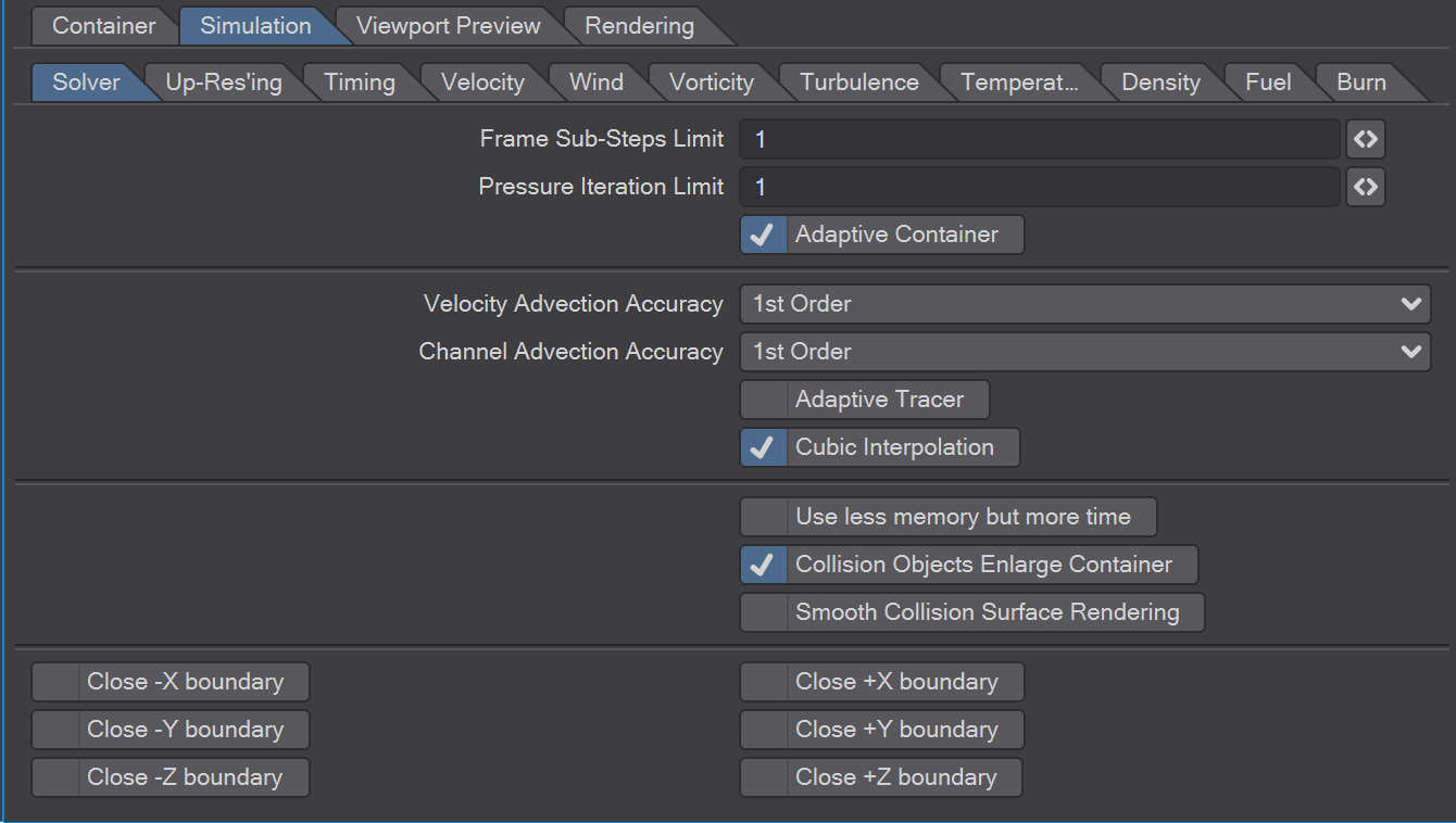
Frame Sub-Steps Limit - For fast moving objects interacting with fluid or to have fluid behave properly under high-speed pressure or other situations will be more accurate by increasing the Sub-Steps Limit. If your simulation has high velocities and you're seeing noise artefacts in the flow, allow the simulation to take more sub-frame time slices, if necessary, by increasing this value. This will allow the simulation to resolve the fluid motion better. It comes at a cost of simulation time and can drastically impact the look of your fluid simulation. Use it sparingly.
Pressure Iteration Limit - Wherever velocity deforms the fluid, pressure is build up. It is a fundamental part of the simulation to equalize this pressure. For simulations that have high velocities and/or collision objects or closed container boundaries, it is recommended to use values between 2 and 10. Values larger than 10 should rarely be necessary. For simulations that don't have collisions and mostly moderate velocities, the simulation time can be kept lower by using the minimum of one iteration.
Adaptive container - If enabled, TFD simulates the smallest possible part of the container in order to save time and memory. The Clip Below parameters in the Velocity, Temperature, Density, Fuel and Burn tabs control when TFD may shrink the container.
Velocity/Channel Advection
The advection accuracy affects the sharpness of the details in the fluid.
1st order - produces a somewhat blurrier result where vortices get smoothed away quicker, but it's also faster and uses less memory.
2nd order - produces sharper details, keeps vortices alive longer but uses more time and memory.
Velocity Advection Accuracy - You can choose between 1st order and 2nd order accuracy here.
Channel Advection Accuracy - You can choose between 1st order and 2nd order accuracy here.
Adaptive Tracer - When advection of the fluid takes place, the simulation traces a trajectory through the velocity field for each voxel. The fluid moves along these trajectories. The default tracer approximates the trajectories with a single line segment. The Adaptive Tracer uses many line segments, such that none of them are longer than the voxel size.
Cubic Interpolation - Moving the channels along the flow requires repeated interpolation. This interpolation slightly blurs the channel each time. Using cubic interpolation reduces this blur at the cost of somewhat higher simulation times.
Use less memory but more time - This is effectively a compression being applied in real-time to the cache data. Since fluid simulation can be very memory intensive, you are likely to exhaust your system's memory with large simulations. In order to allow you to run larger simulations on machines with less memory, checking this option will let TurbulenceFD use less internal caches which results in less memory being used but more simulation time being required. Render times are not affected. This will produce smaller .bcf files on a stored drive.
Collision Objects Enlarge Container - The adaptive container will be enlarged to contain all collision objects by default. This may not be necessary, especially if the objects aren't moving. In such a setup, you can uncheck this option to keep the container smaller. Smooth Collision Surface Rendering - When rendering solid obstacles emerged in the fluid, extrapolation will avoid artefacts on the surface of the obstacle. If you have invisible or transparent obstacles, disable this option.
Close Boundaries - By default the sides of the fluid container are open. The fluid can just move out of the container and disappear. If you want to simulate a closed or partially closed space, you can select the sides of the container that will be closed. The checkboxes are labeled according to the half-spaces of the coordinate system. That is, +X is the side of the container in the positive X direction and so on. For example, a ground explosion can be simulated in a container with the -Y side closed to avoid having fluid leave the container through the ground. Making use of these check boxes in certain scenes can reduce the need for a "wall, ceiling, floor" collision object to be used in the Emitter Tab as a collision object when the effect of having one is desired, thus reducing simulation times.
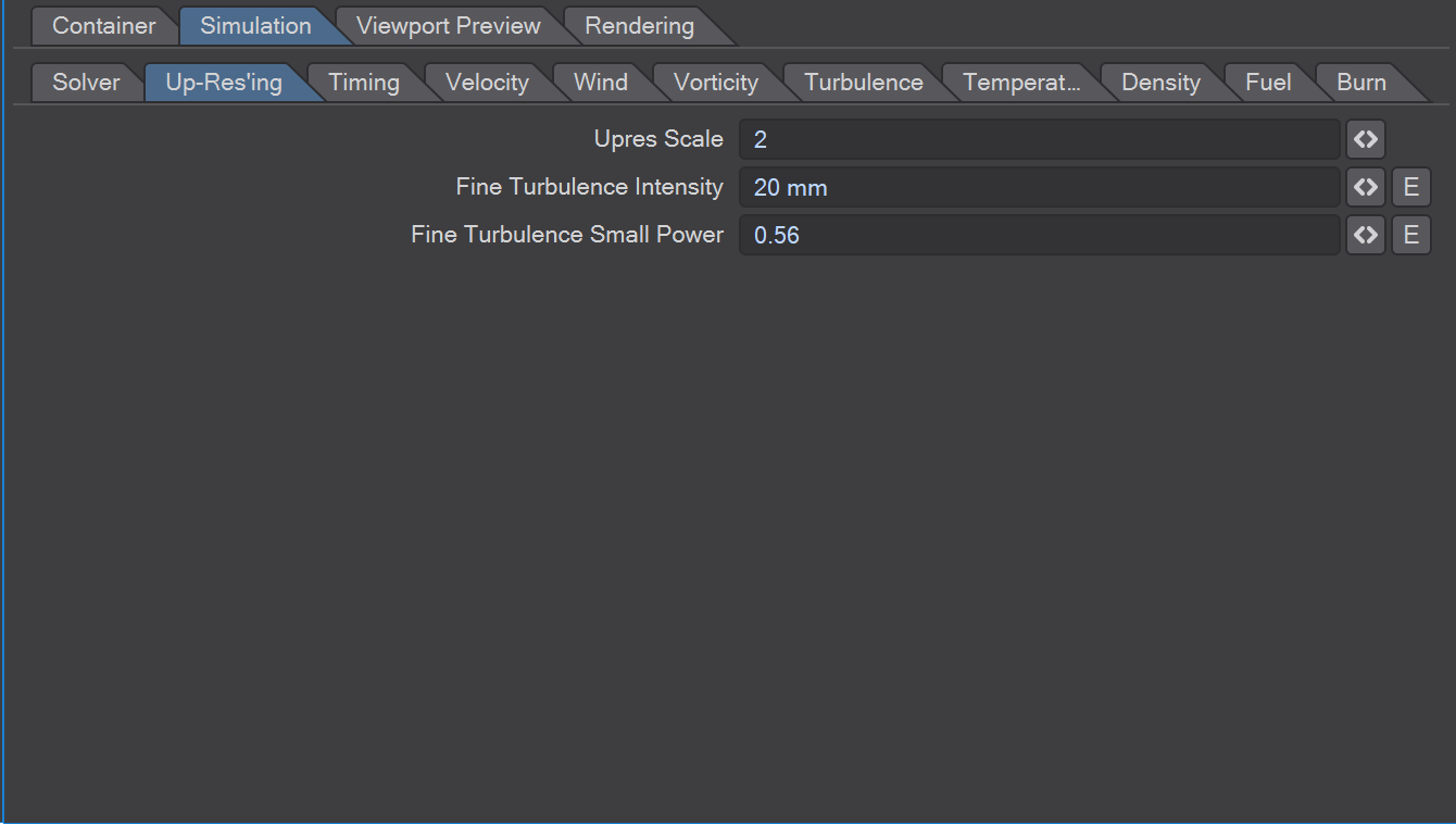
Upres Scale - When running an Up-Res'ing post-process by clicking the Up-Res button, the resolution of an existing simulation will be increased. This parameter specifies how much larger the resolution will be.
Fine Turbulence Intensity - The Up-Res'ing post-process also adds small scale turbulence to the fluid that will create additional detail. This parameter specifies the strength of this small scale turbulence.
Fine Turbulence Small Power - Specifies how stong small turbulence detail is compared to the next larger size. This works just like the Simulation/Turbulence/Small Power parameter but it's applied only for the additional detail added during Up-Res'ing.
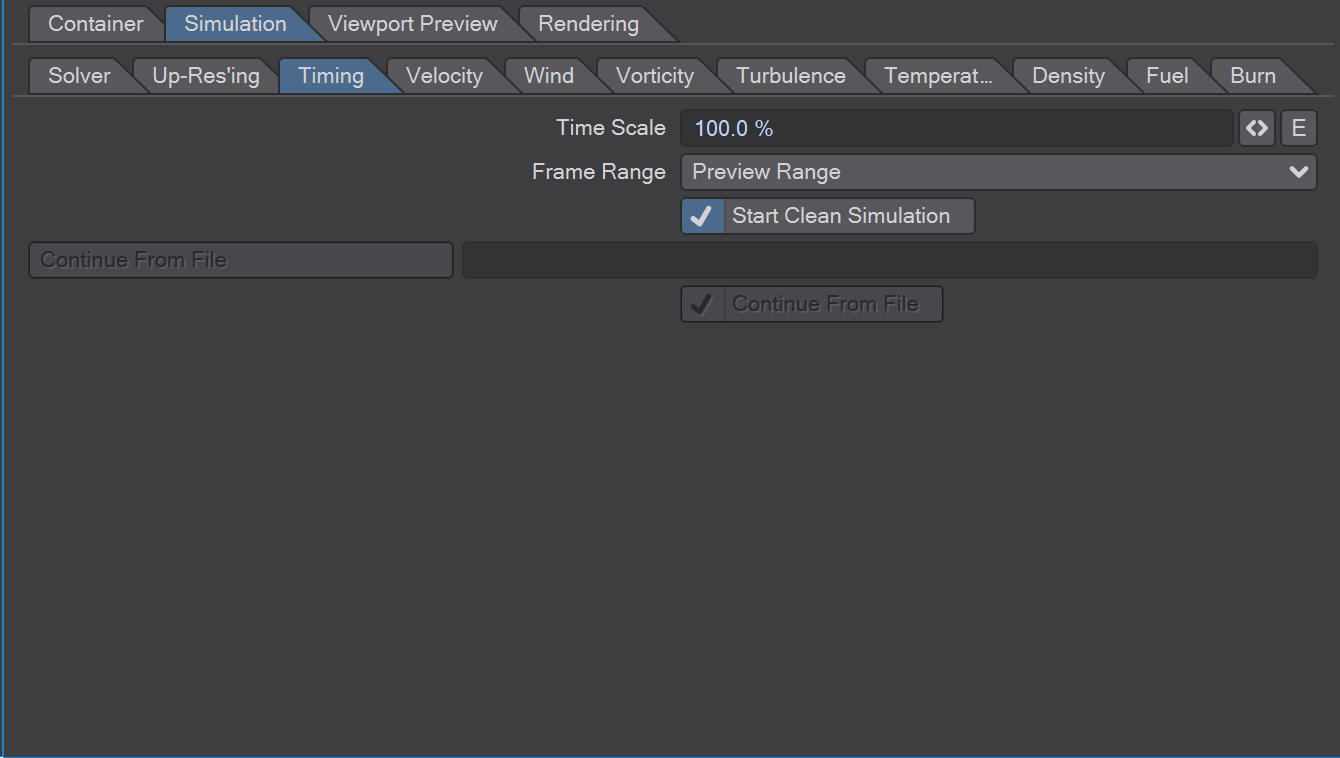
Time Scale - This value controls how fast time will pass for the simulation. At 1.0, the simulation will run at the same speed as the animation. Values below 1.0 slow the simulation down, values above 1.0 speed it up. You can for example animate this value down to 0.0 to create bullet-time-like animations.
Frame Range - This setting specifies what part of the time-line to simulate. It corresponds to LightWave's Preview Range and Render Range.
Start Clean Simulation - Clear all channels before starting the simulation at the frame specified above.
If not checked, you can continue from a previously-saved cache.
Load Simulation State From File - If Start Clean Simulation is unchecked, channels will be initialized from the file specified here. The file may be any .bcf file from a TurbulenceFD cache directory. Channels that are not available in the .bcf file will be cleared as if Start Clean Simulation was checked. See the parameters in the Cache tab for information about how to control which channels are saved to the disk cache.
Continue Simulation From File - If checked, the next simulation run will load the state from the file specified above and jump to the frame following the one cached to the file. Use this to continue a simulation at any cached frame, possibly after changing some parameters.
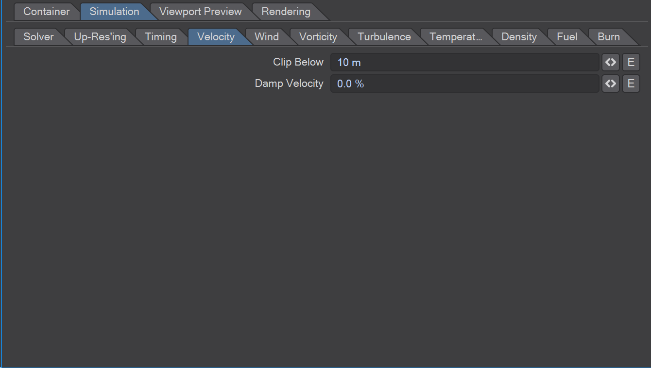
Clip Below - Specifies the minimum velocity in voxels per second that will prevent the container from adapting its size. Velocities below that will be cut off when the container adapts its size. The default value is chosen such that it works with most simulations, including explosions which need lower values than other simulations. However, at the default value the container may be lept larger than necessary. If you want to speed up the simulation by letting the container adapt more tightly to the channels, increase this threshold. A value of e.g. 1000 will effectively ignore the velocity when adapting the container.
See also the threshold parameters of the channels below.
Damp Velocity - Specifies the percentage by which the velocity is reduced in each frame. This simulates drag or friction in the air. This is for example useful for explosions where you may want the fluid to leave the source quickly but then form a cloud that moves slower.
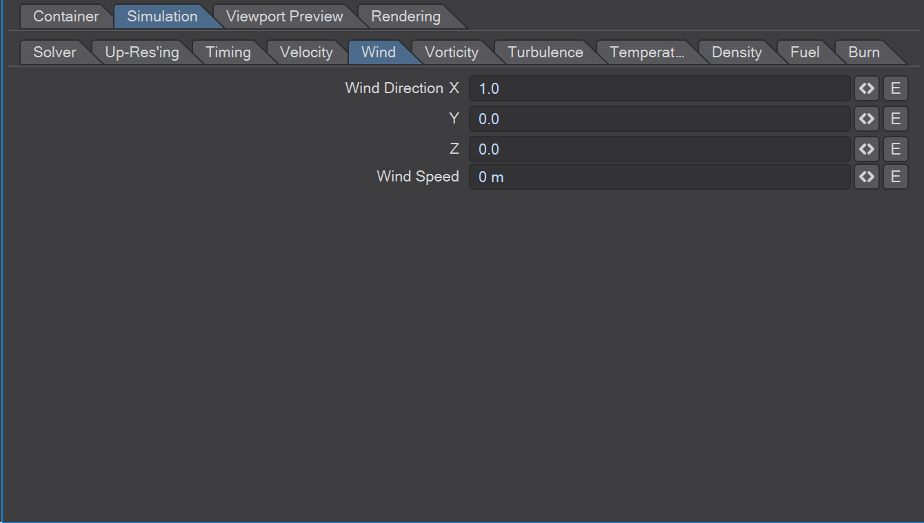
Wind Direction - Specifies the direction of a global wind in the container.
Wind Speed - Specifies the speed of the global wind in the container.
These two wind operators allow you to define a global wind that is blowing in the fluid container. It can be used to add wind as it would appear in an outdoor scene. To create small, local winds like from an exhaust pipe, use the Normal Force parameter on an emitter object (e.g. a plane or disc).
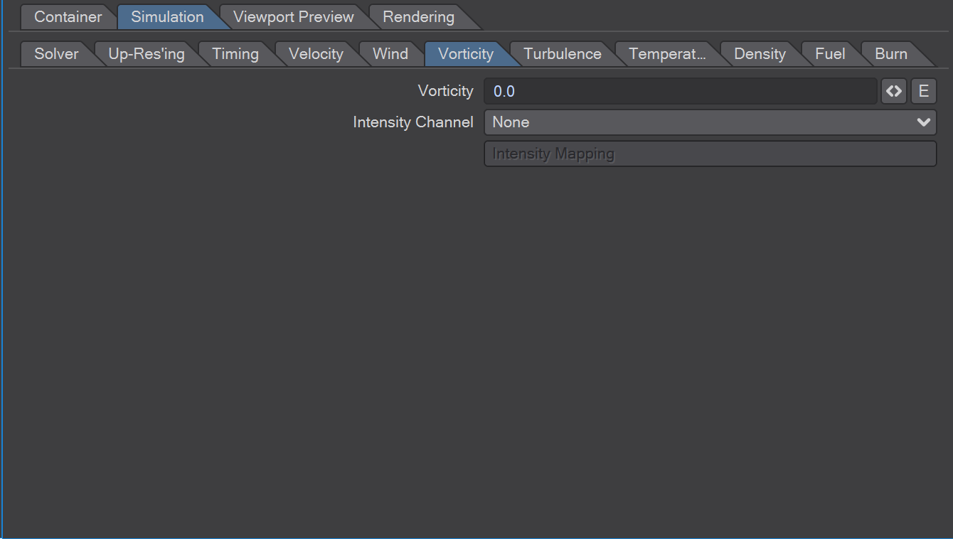
This set of functions provides amplification to existing curls to keep them alive longer. When using strong amplification, the curls will get stronger and stronger. After some time, the flow may become very noisy. To avoid that, the Intensity Channel and Mapping allow you to restrict the effect of Vorticity to a region that you control using another fluid channel.
Vorticity - Sets the strength of amplification for small curls.
Intensity Channel - You can control the vorticity in space using any of the fluid channels. Use this to amplify the curls only where the temperature is high enough, for example.
Intensity Mapping - For improved control over the intensities, the values of the Intensity Channel are re-mapped by this F-curve before scaling the vorticity.
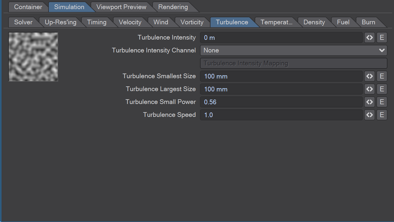
Adds random velocity noise to the container, making it swirl and a chaotic way as you would expect from turbulent fire or similar. It is driven by a procedural noise function that changes over time. The following parameters control the intensity, scale, etc. of this texture.
Turb. Intensity - Specifies the strength of the turbulence.
Intensity Channel - You can control the turbulence intensity in space using any of the fluid channels. Use this to add turbulence only where the temperature is high enough, for example.
Intensity Mapping - For improved control over the intensities, the values of the Intensity Channel are re-mapped by this f-curve before scaling the turbulence intensity.
Smallest Size - Specifies the size of the smallest curls added to the fluid.
Largest Size - Specifies the size of the largest curls added to the fluid.
Small Power - Specifies how strong small curls are with respect to the next larger ones. A small power of 1.0 will make curls of all sizes equally strong. A small power of 0.5 will make small curls half as strong as curls of twice the size.
Speed - This value specifies how fast the turbulence field changes over time.
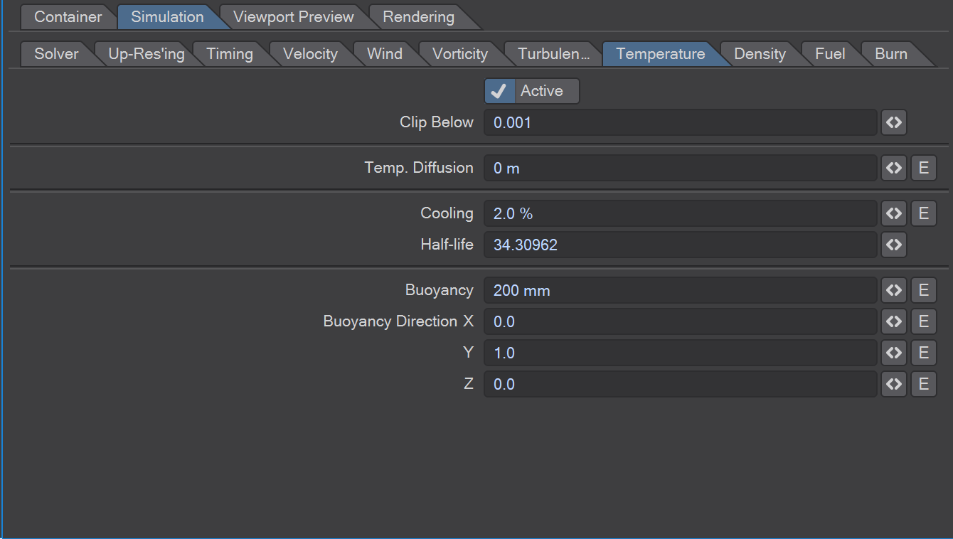
Active - Checkbox. Without this active, the following settings are ghosted. This option is active by default to enable simulation and caching of the temperature channel.
Clip Below - If the Adaptive Container option is enabled, this value defines the minimum temperature that will cause the container will consider non-empty. If this value is zero, no voxels containing temperature will be lost. However, often shading settings are such that low values aren't visible anyway. In this case, increasing this threshold allows the sim to keep the container smaller.
Temp. Diffusion - Air mixes even if it does not move on the large scale. This effect is called Brownian Motion. Diffusion accounts for this effect by basically blurring the temperature. As a result of high diffusion, the buoyancy force becomes smoother.
Cooling - Specifies the percentage by which the temperature is cooled down in every frame. Cooling works like exponential decay in the Burn channel.
Half-life - Instead of specifying the cooling intensity as percentage per frame, you can specify the time it takes for the temperature to cool down to half its value. This may be more intuitive in many situations. Note that "no cooling" would mean infinite half-life.
Buoyancy - Buoyancy is the force that makes warm air rise and cold air sink. This value specifies the force per unit of temperature exerted on a particle.
Buoyancy Direction - specifies the direction of the buoyancy force.
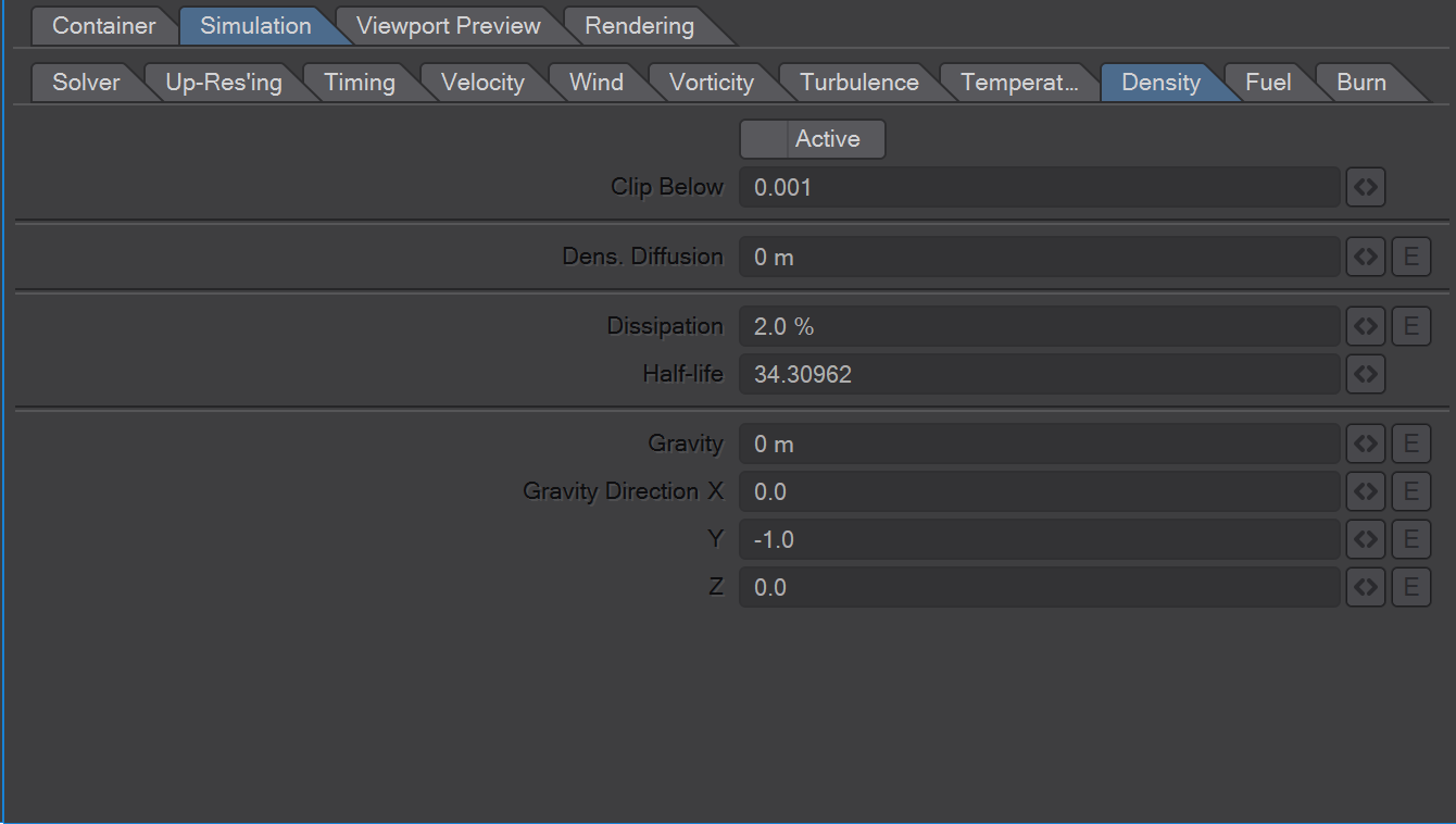
Active - Check this to enable simulation and caching of the density channel.
Clip Below - If the Adaptive Container option is enabled, this value defines the minimum temperature that will cause the container will consider non-empty. If this value is zero, no voxels containing temperature will be lost. However, often shading settings are such that low values aren't visible anyway. In this case, increasing this threshold allows the sim to keep the container smaller.
Dens. Diffusion - Air mixes even if it does not move on the large scale. This effect is called Brownian Motion. Diffusion accounts for this effect by basically blurring the density.
Dissipation - Specifies the percentage by which density is dissipated in every frame. Dissipation works like exponential decay in the Burn channel.
Half-life - Instead of specifying the dissipation intensity as percentage per frame, you can specify the time it takes for the density to dissipate to half its value. This may be more intuitive in many situations.
Gravity - The more dense the fluid is, the more mass it has. Therefore, the more it gets affected by the gravity force. This parameter specifies the strength of that force.
Gravity Direction - specifies the direction of the gravity force.
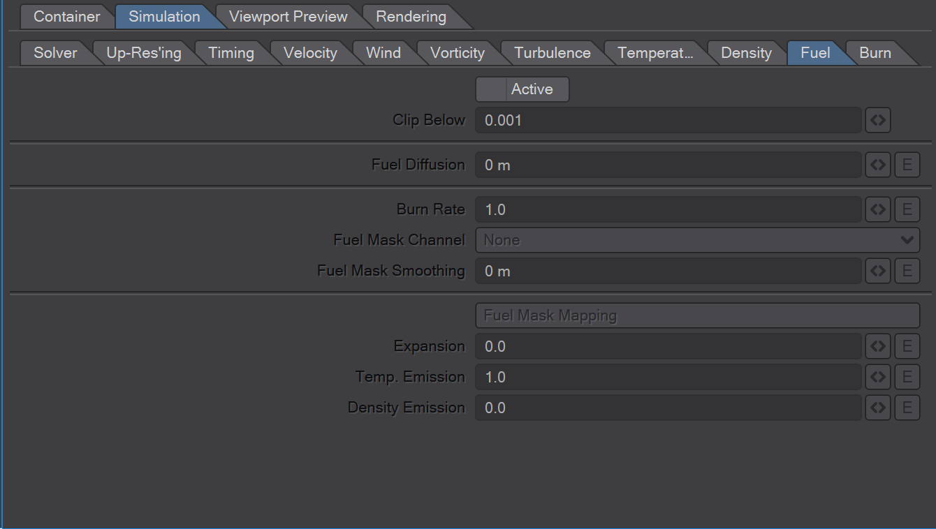
Fuel works like a cloud of combustible gas like propane or gasoline mist. When it burns, it...
emits Burn which then represents the burning flame
expands the cloud (i.e. it emits pressure)
emits heat (see Temp. Emission)
emits soot (see Density Emission)
reduces the amount of fuel left
Fuel Masking allows you to control where fuel burns. The Fuel Mask is a cloud taken from any other channel, smoothed and re-mapped. Only within that cloud the fuel will burn. This allows you to control ignition and suffocation of burning fuel.
Active - Check this to enable simulation and caching of the fuel channel.
Clip Below - If the Adaptive Container option is enabled, this value defines the minimum temperature that will cause the container will consider non-empty. If this value is zero, no voxels containing temperature will be lost. However, often shading settings are such that low values aren't visible anyway. In this case, increasing this threshold allows the sim to keep the container smaller.
Fuel Diffusion - Specifies how fast fuel diffuses (see Temperature/Diffusion above for more details).
Burn Rate - Specifies the amount of the fuel that is burnt in every frame. The faster it burns, the more Burn and Temperature will be created. Burn Rate works like linear decay in the Burn channel.
Fuel Mask Channel - If a channel is selected, fuel masking will be active. See the simple-ignition example for a setup using the Burn channel.
Fuel Mask Smoothing - Before using the selected channel as a fuel mask, it can be smoothed or blurred. This will also make the cloud a bit larger, thereby propagating the ignition front like you would expect it to.
Fuel Mask Mapping - Re-mapping the smoothed fuel mask gives you control over the shape of the fuel mask and how steep the ignition front is. A flat increase will let the burn start slowly the larger the fuel mask values become. A steep increase will make the fuel burn at the full burn rate as soon as it touches the fuel mask.
Expansion - A factor that specifies how much the gas expands per burnt voxel of fuel.
Temp. Emission - Specifies how much heat is generated per unit of burnt fuel. Density Emission - Specifies how much density is generated per unit of burnt fuel.
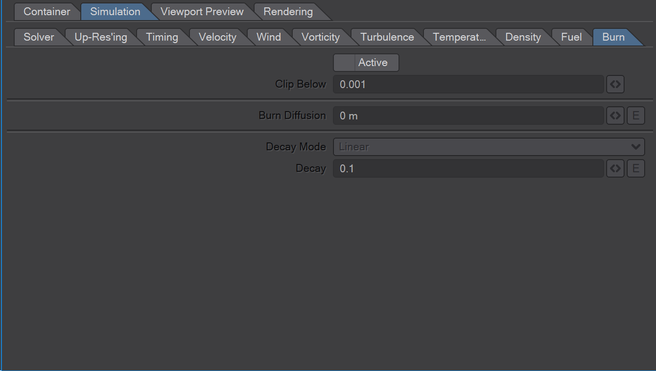
Active - Check this to enable simulation and caching of the burn channel.
Clip Below - If the Adaptive Container option is enabled, this value defines the minimum temperature that will cause the container will consider non-empty. If this value is zero, no voxels containing temperature will be lost. However, often shading settings are such that low values aren't visible anyway. In this case, increasing this threshold allows the sim to keep the container smaller.
Burn Diffusion - Specifies how fast Burn diffuses (see Temperature/Diffusion above for more details).
Decay Mode - Decaying a channel can be done by a constant amount or by a percentage of the current value. The Decay Mode specifies which will be used.
Linear - Decay the burn channel by subtracting a constant value in each frame. If you emit 1.0 into the burn channel, setting Decay to 0.1 in this mode will let the emission live for 10 frames before it drops to zero. This mode works well for flames that have a sharp contour.
Exponential-Decay the burn channel by subtracting a percentage of the current value (of a voxel) in each frame. As the current value becomes smaller and smaller, so does the value that is subtracted. Therefore the emission never drops back to zero - only very close. And the speed at which is drops will get slower and slower. This is the type of decay that temperature and density have. It models the way dust slowly dissipates in air. The decision of which mode to use is mostly driven by your shading settings. To get an idea of how the modes differ, compare the histograms in the shader's mapping curve editors. The exponentially decayed channel will have lots of low values and less high values, because the decay slows down the smaller the values get. The linear decay more uniform distribution of high to low values. This makes shading sharp contours easier with the linear mode. If you want the channel values to live long and build up a more smoke-like cloud, the exponential decay works better.
Decay - In linear mode, Decay specifies the constant value that will be subtracted from the current channel value in each frame. In exponential mode, it's the percentage of the current value that will be subtracted.
Half-life - Instead of specifying the decay intensity as percentage per frame, you can specify the time it takes for the channel value to decay to half its value. This may be more intuitive in many situations. For example, if Half-Life is one frame, the channel value drops to 50% within one frame. That corresponds to a Decay of 50%.
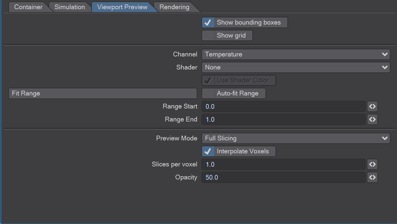
Show Bounding Boxes - Check to display the bounding boxes. The clipping box is displayed in white, the simulated region-of-interest is displayed in green.
Show Grid - Check in order to display the container's grid in the viewport. This allows you to visualize the resolution of the fluid container.
Channel - Select the fluid channel that you want displayed in the viewport.
Shader - Select the shader you want applied to the viewport preview. If this selection is None, the generic color scale and range fitting is used to shade the values.
Note that for performance reasons some of the shading features are not applied to the viewport preview.
The preview does not apply the following:
Smoothing
Separate Opacity
Sub-Grid Detail
Illumination
Motion Blur
Distance/Opacity Mapping
Use Shader Color - If checked, the shader's color settings are used for the preview. Else, only its mapping is used along with the generic color scale.
Fit Range - Full Slicing mode renders the whole 3D volume semi-transparent with opacity and color depending on the channel values. Single Slice mode renders a 2D slice of the volume and allows for close inspection of the values.
Auto-fit Range - If checked, the range will be fit to the current frame automatically.
Range Start and End - The Start value for the displayed range. All values in the channel that are below or equal to the Range Start will be displayed with the color at the low end of the gradient. The End value for the displayed range. All values in the channel that are above or equal to the Range End will be displayed with the color at the high end of the gradient.
Preview Mode - Full Slicing mode renders the whole 3D volume semi-transparent with opacity and color depending on the channel values. Single Slice mode renders a 2D slice of the volume and allows for close inspection of the values.
Interpolate Voxels - Uncheck this if you want to see the separate voxels more clearly.
Slices per voxel - Available in Full Slicing Mode. The higher this value is, the smoother the preview will look. Values above 2 may not improve the result significantly because of the limited color resolution of the OpenGL framebuffer.
Opacity - Available in Full Slicing Mode. This function sets the overall opacity of the preview to high values in order to amplify the faint parts of the fluid. Bring it down to smaller values in order to see the inner core of the fluid cloud.
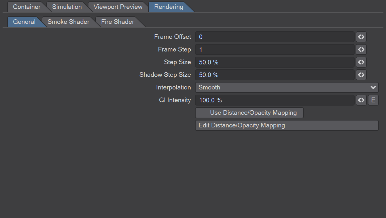
Frame Offset - This offset is added to the current frame number to determine the frame used for rendering. You can use this to create instances of the container that render with a different frame offset each.
Frame Step - By default the render sequence will be the same as the simulation sequence. If you want to render a simulation in backward order, set this value to -1 and the Frame Offset to the end of the frame range. You can also skip frames by using values larger than 1 (or smaller than -1). Using a values of 0 allows you to freeze a fluid frame while animating the rest of the scene.
Step Size - Specifies the step size as a percentage of a voxel that is used to sample the fluid container. Large values make renders faster but can introduce noise. Smaller values reduce noise but need more time. You should reduce this value only if you see noise artifacts in your renders to avoid increasing the render times unnecessarily.
Shadow Step Size - Shadow rays are usually more robust and produced without noise artifacts. Setting a higher step size for these rays allows you to save render time. This is particularly effective for lit smoke renders.
Interpolation - Specifies the way values are interpolated from the simulation grids. Fast can be somewhat blurry and have banding artifacts. Smooth is the blurriest but avoids banding completely. Sharp avoids blurriness but can have banding artifacts. Note that you can always reduce or even remove blurriness by using steep Mapping curves in the shader settings, even when using Smooth interpolation. Also note that the illumination method (see below) can be the reason for banding as well.
GI Intensity - Scales the intensity of the light emitted from the fluid when rendering with Radiosity enabled.
Use Distance/Opacity Mapping - Enable the mapping of distance from camera to fluid opacity. See below for details.
Distance/Opacity Mapping - Maps the distance from the camera to an opacity for fluid rendering. This can be used when flying the camera through a cloud. Voxels that are very close to the camera may occlude too much of the cloud or they may simply be too big and look blobby. You can fade away their opacity using this mapping.
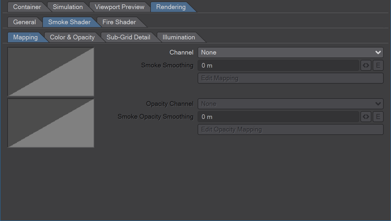
Channel - Select the simulation channel that you want the shader to use as input.
Smoothing - Blur the field before using it as shader input.
Mapping - This function curve (f-curve) allows you to map the input values to an intensity curve before they are used to determine the smoke's color and opacity. A linear 0 to 1 gradient will leave the values unchanged. To edit the Mapping, click on the curve to open the F-curve editor. See the section on using the f-curve editor for details.
Opacity Channel - To use a separate channel to control the smoke's opacity, select it here. If you use it, the first channel, smoothing and mapping parameters will only control the smoke color. The Smoothing and Mapping parameters below will affect only the opacity.
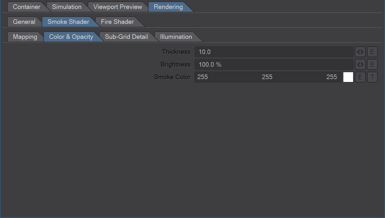
Thickness - Low values can be used for steam or vapor, high values for thick smoke. Unlike rigid bodies, smoke particles usually do not fill space up completely. Therefore, smoke is always partially transparent. However, the larger the distance that light travels through smoke and the thicker it is, the higher the probability that light rays hit a smoke particle and get scattered or absorbed. That is, while you may be able to look through 1 inch of smoke at thickness 1, 10 inches may be virtually opaque. At thickness 10 however, you may not even be able to look through 1 inch of smoke.
Brightness - The brighter the smoke, the more it will reflect incoming light. You can also adjust the smoke's brightness using the Smoke Color below, but this parameter allows for HDR brightness ranges and is easier to adjust - especially if you have a gradient set for the Smoke Color.
Smoke Color - Defines the smoke color gradient. It assigns colors to re-mapped channel values. The default is to use a single color for all input values (0 to 1) and let only opacity and illumination shade the smoke.
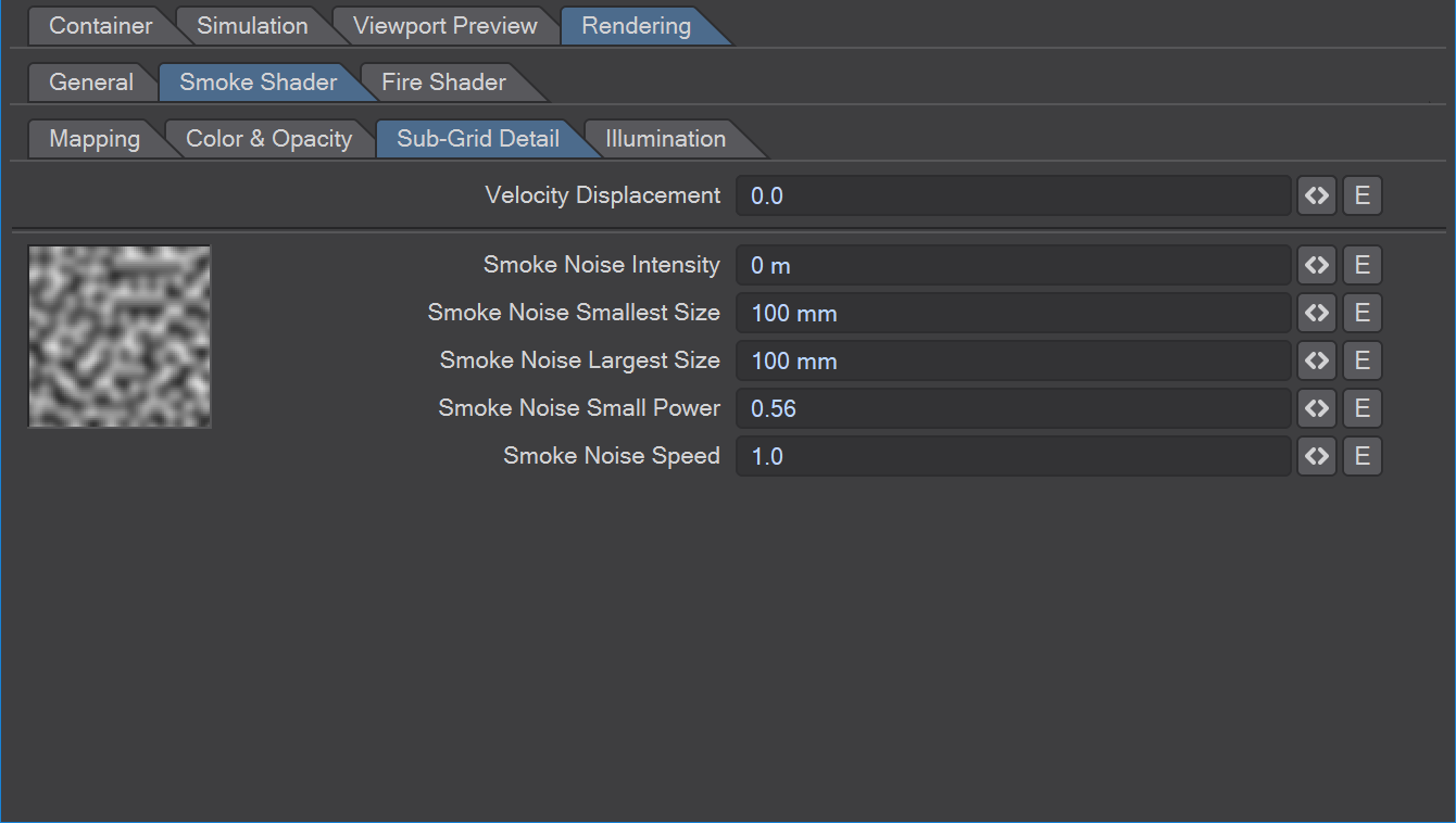
There are two type of render-time sub-grid detail. Both work at render time without requiring a re-simulation.
Velocity displacement deforms the fluid during rendering and can produce very sharp details.
Sub-Grid Noise adds detail to the fluid animates over time.
Velocity Displacement works only if a Velocity Cache is available (see Container). Sub-Grid noise works without a Velocity Cache, but for smooth animation you should also have the Velocity Cache available. Both options increase the render time.
Velocity Displacement - Velocity Displacement warps the fluid forward or backward in time, depending on the value you set. Rendering times will be higher, so this is disabled in fast preview mode. Low values can add more detail while introducing very little noticeable deformation. Higher values can change the appearance of the fluid drastically but produce rather interesting effects. Note that you will have to enable Cache Velocity in the Simulation/Cache tab in order to be able to use Velocity Displacement.
Noise Intensity - Specifies how strong the noise will affect the shaded fluid.
Smallest Size - Specifies the size of the smallest noise.
Largest Size - Specifies the size of the largest noise.
Note that the larger the difference between Smallest and Largest scale, more render time will be needed.
Small Power - Specifies how strong small detail is with respect to the next larger ones. A small power of 1.0 will make curls of all sizes equally strong. A small power of 0.5 will make small curls half as strong as curls of twice the size.
Speed - This value specifies how fast the turbulence field changes over time.
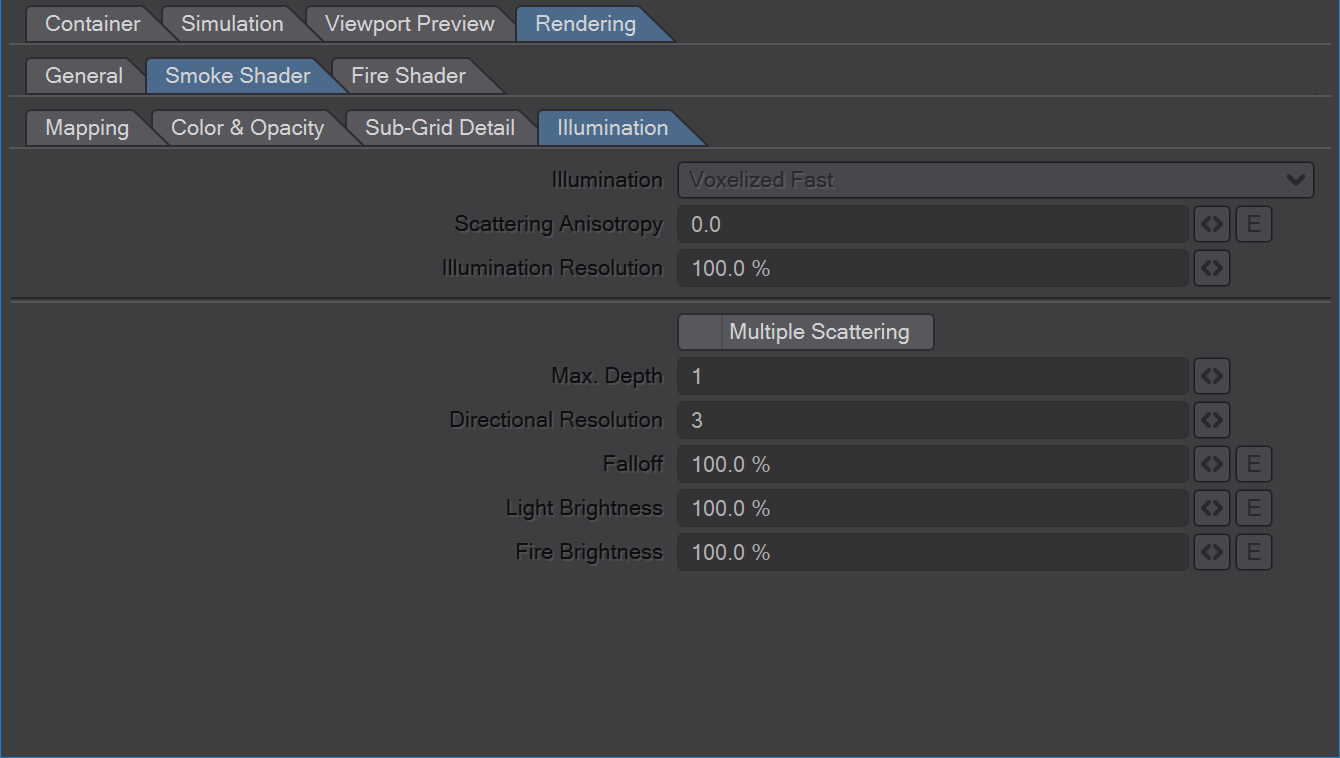
Illuminating smoke is the most time-consuming part of a rendering gaseous fluids. TurbulenceFD offers several illumination modes with different speed and quality to choose from. In the list, the speed decreases (first mode is fastest, last mode is slowest) and quality increases (first mode has lowest quality, last mode has best quality).
Note that the default Fast mode may be all you need in many scenes even at high quality requirements. However, the thicker the smoke gets, the more likely you're going to see stairstep artifacts. In these situations, choose the fastest mode that delivers the quality you need.
None - No illumination at all
Fast - Low Quality
Smooth - Medium Quality
Optimal - Slowest, Lowest Memory Usage
Both Corrected modes use more memory with each additional light source that illuminates the fluid container.
Scattering Anisotropy - When light hits a gas it either gets absorbed or bounces off into a different direction. Different types of gases have different preferences of directions into which they scatter light. Water vapor for example tends to scatter light in forward direction. That means that most of the light that hits the vapor does not change its direction too much and continues to travel forward. As a result, the vapor will be brighter when the camera is on the other side of the vapor cloud as the light source.
The Scattering Anisotropy parameter specifies the preferred direction of light scattering. A positive value means forward scattering, a negative value means backward scattering. For example, a value of 1.0 means that the light does not change it's direction at all. You will only see lit smoke if the camera is looking at the light source at the exact angle of the light. Vice versa, a value of -1.0 means that the camera has to look into the same direction as the light to catch any light scattered off the smoke. All light is scattered in exactly the opposite of it's incoming direction.
The neutral value of 0.0 means that light gets scattered into all directions equally.
In practice, you would usually only use small values like 0.2 to get brighter backlit smoke for example.
Illumination Resolution - Illuminating smoke takes up most of the render time. You might want to reduce the resolution at which the illumination is computed to save render time. On the other hand, if you have extremely thick smoke, you may see grid artifacts unless you increase the illumination resolution.
Multiple Scattering-Enabling Multiple Scattering allows for two effects.
It works like Global Illumination for smoke. That is, it computes additional bounces of light inside the smoke, effectively making it brighter. This is the preferred way of creating ambient light. Using the ambient light parameter on the light source will create a low-quality approximation of this effect.
It allows for the Fire Shader to illuminate the smoke.
Max. Depth - The higher the Depth value, the more bounces will be computed. More bounces will make the smoke brighter but also cost more render time. You can create a cheap approximation of a higher Depth value by lowering the Falloff instead.
Directional Resolution - Increase this value if you see ray artefacts in your smoke. A higher Directional Resolution will increase the render time.
Falloff - The higher this value, the faster the light will fall off as it travels through smoke. You can get brighter smoke by using a lower value here.
Light Brightness - This allows you to separately adjust how much external lights contribute to Multiple Scattering.
Fire Brightness - This allows you to separately adjust how much brightness the Fire Shader contributes to Multiple Scattering calculations.
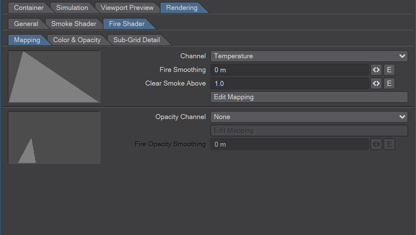
Channel - Select the simulation channel that you want the shader to use as input.
Fire Smoothing - Blur the field before using it as shader input.
Clear Smoke Above - You may want to remove all smoke from the region where fire is shaded to allow for a clearer flame. This value specifies the mapping intensity above which fire will erase smoke for shading.
Mapping - This function curve (f-curve) allows you to map the input values to an intensity curve before they are used to determine the fire color and opacity. A linear 0 to 1 gradient will leave the values unchanged. To edit the Mapping, click on the curve to open the f-curve editor. See the section on using the f-curve editor for details.
Opacity Channel - To use a separate channel to control the fire's opacity, select it here. If you use it, the first channel, smoothing and mapping parameters will only control the fire color. The Smoothing and Mapping parameters below will affect only the opacity.
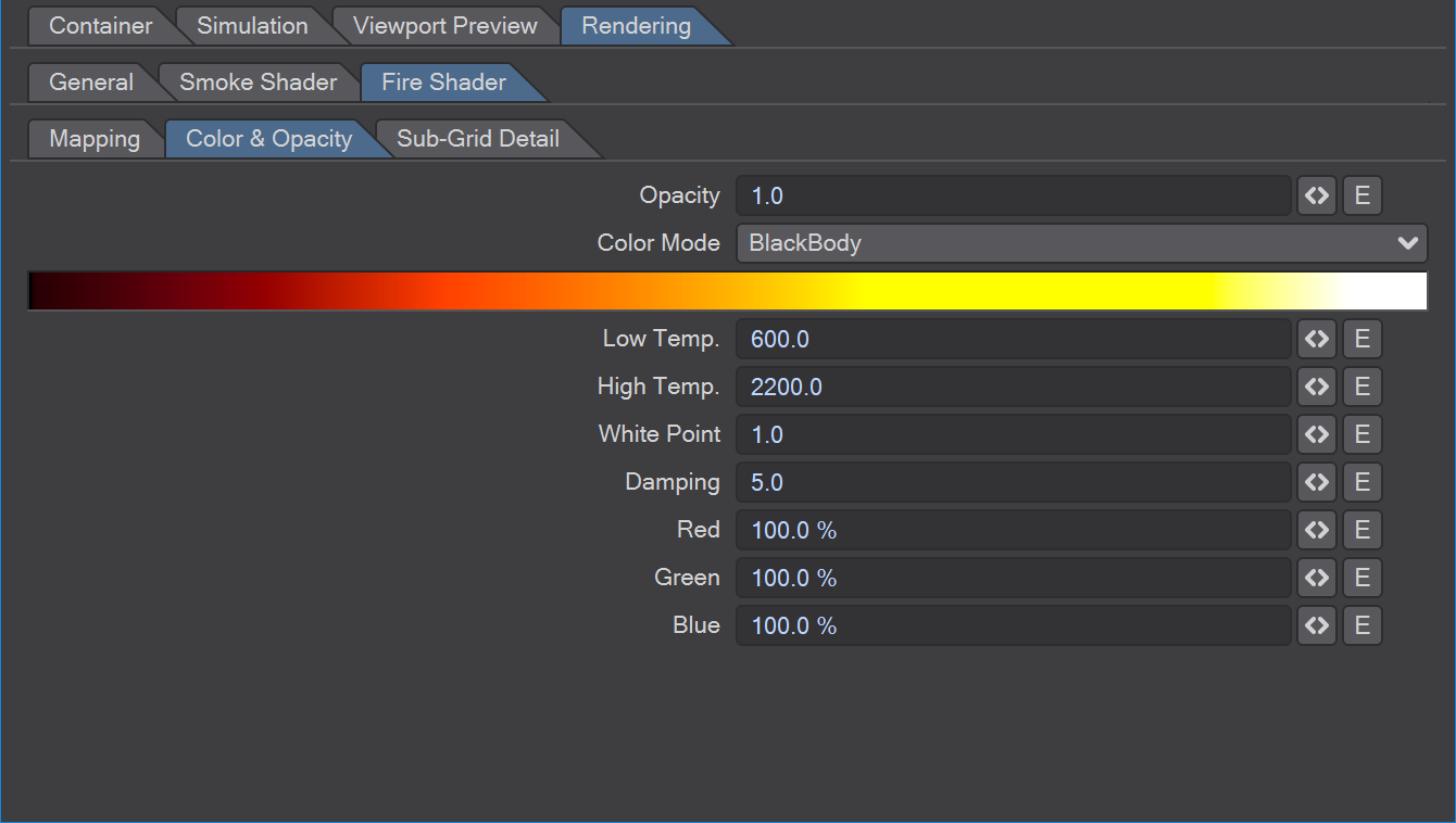
Opacity - Specifies the opacity of fire. Fire opacity also affects the brightness of the flame. The more glowing particles there are, the more they will obscure the background and the more light will be emitted.
Color Mode - Selects the way the color gradient is defined. Manual Color allows you to specify a color gradient directly, while Black Body Color will use a physical model to compute the color.
Fire Color - Available in Manual Color mode.
If Manual Color Mode is selected, you specify the color gradient here. Make sure that you use a high dynamic range of colors (intensities larger than 100%) and that the Clamp checkbox is not checked.
Luminance - Available in Manual Color mode. Defines the overall color intensity in Manual Mode.
Low Temp. - Available in Black Body mode. In Black Body Color Mode, this value gives the color temperature corresponding to an input value of 0 from the simulation channel. It's most intuitive to observe the gradient above to see this parameter's effect.
High Temp. - Available in Black Body mode. In Black Body Color Mode, this value gives the color temperature corresponding to an input value of 1 from the simulation channel. It's most intuitive to observe the gradient above to see this parameter's effect.
White Point - Available in Black Body mode. Fire has an enormous dynamic range. The white point is used to map it to a lower dynamic range used for you renders. It's most intuitive to observe the gradient above to see this parameter's effect.
Damping - Available in Black Body mode. Instead, or in addition to adjusting the white point, you can damp the dynamic range using this parameter. The higher the value the darker the colors will be.
Red/Green/Blue - Available in Black Body mode. The Black Body color model is an idealization of carbon-based light emission. In real fires plenty of other chemicals are burnt or created during the reaction. These controls let you change the tint of the fire color to allow for a broader spectrum of colors. For example, you may want to add more red (or remove green and blue instead) to get closer to the look of oilier fires.
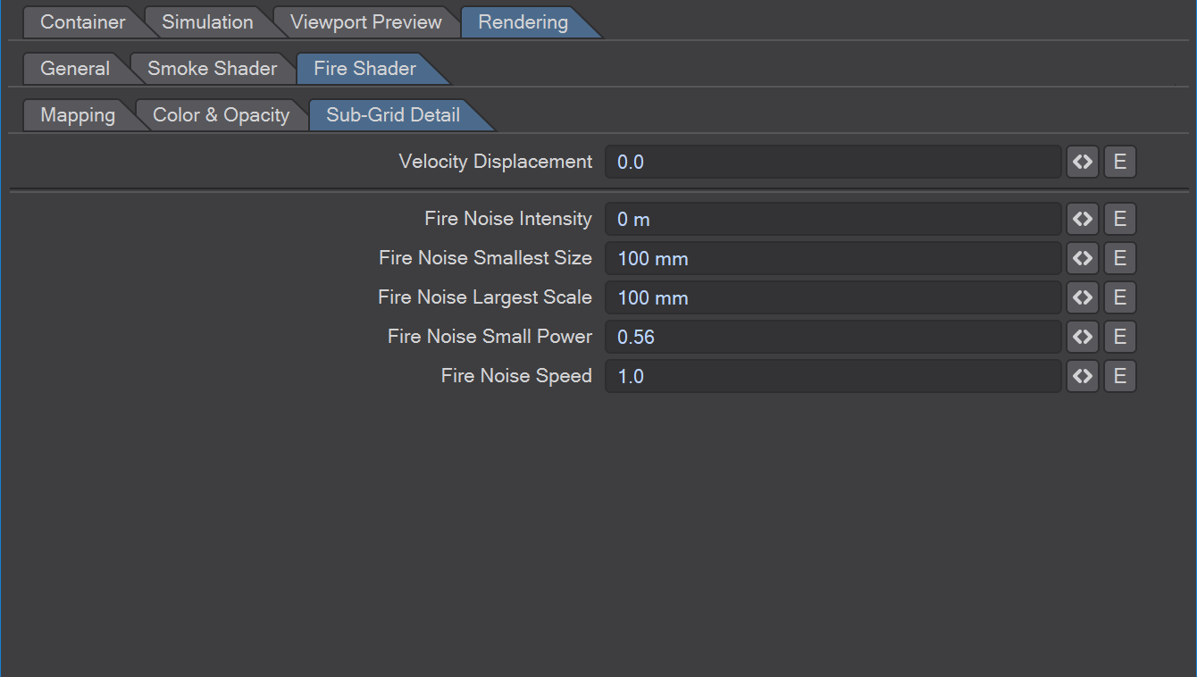
There are two type of render-time sub-grid detail. Both work at render time without requiring a re-simulation.
Velocity displacement deforms the fluid during rendering and can produce very sharp details.
Sub-Grid Noise adds detail to the fluid that animates over time.
Velocity Displacement works only if a Velocity Cache is available (see Container). Sub-Grid noise works without a Velocity Cache, but for smooth animation you should also have the Velocity Cache available.
Both options increase the render time.
Velocity Displacement - Velocity Displacement warps the field forward or backward in time, depending on the value you set. Rendering times will be higher, so this is disabled in fast preview mode. Low values can add more detail while introducing very little noticeable deformation. Higher values can change the appearance of the field very much but produce interesting effects. Note that you will have to enable Cache Velocity in the Simulation/Cache tab in order to be able to use Velocity Displacement.
Noise Intensity - Specifies how strong the noise will affect the shaded fluid.
Smallest Size - Specifies the size of the smallest noise.
Largest Size - Specifies the size of the largest noise. Note that the larger the difference between Smallest and Largest scale, the more render time will be needed.
Small Power - Specifies how strong small detail is with respect to the next larger ones. A small power of 1.0 will make curls of all sizes equally strong. A small power of 0.5 will make small curls half as strong as curls of twice the size.
Speed - This value specifies how fast the turbulence field changes over time.