Bottom Menu
Bottom Edge Menu
Info Display
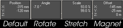
Just above the grid display in the lower left-hand corner of Modeler is the Information Display. Most of the time this gives you feedback on the position of your mouse. However, depending on what you are doing, it can also display a variety of other information.Below are a few examples of what might be displayed with various tools:
Grid Info Field
A grid of squares - cleverly known as the grid - is visible in any of the orthogonal views, as well as the Perspective view. The grid serves as a visual reference when you move items around, but it will never render in a final image. The grid lines are darker every tenth square for visual reference. The Origin is located at the center of the grid.
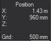
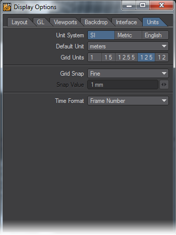
You can find the current size of the grid squares in the Grid Information field at the very lower-left corner of the screen. Set the Unit System, Default Unit, and other options pertaining to the Grid in the Display Options Window.
Modes: Action Center Control
Many Modeler tools (i.e., Rotate, Size, Stretch, Twist, Taper1, Taper2, Vortex, Pole1, and Pole2) can use different centers. This Action Center is located at the bottom of Modeler’s Interface.

- Mouse (Shift F5) - means to use the mouse position.
- Selection (Shift F8) - uses the center of a bounding box around what is currently selected.
- Pivot (Shift F7) - uses the first active layer’s pivot point.
- Origin (Shift F6) - means to use the very center of the universe: XYZ 0, 0, 0.
Numeric Panel
(default keyboard shortcut N)
The Numeric Panel is a multi-functional non-modal window. Its contents and abilities change depending on what tool is selected. When you create primitives, it lets you refine graphically set values. When you use modifying tools, it lets you change various settings that affect how the tool performs. The Numeric Panel is located at the bottom of Modeler’s Interface, or by just pressing the N key. It may be left open continuously.
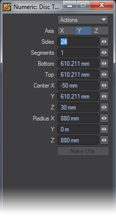
Use the Actions pop-up menu to Reset the fields to their default settings or to Activate the tool. (You can also press the N key to activate the tool.) Activating a tool turns on its interactive handles, if any, in the viewports. This can be for primitive shape, influence range, and so on. It will also activate the numeric fields, if they are ghosted.
You can also reset to defaults by clicking a reset area when a tool is selected, but not activated.
Drop Tool Command
(default keyboard shortcut Return)
The Drop Tool command (Located at the bottom of the Modeler interface) will commit to the changes made with the currently selected tool and will deactivate the current tool.
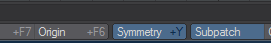
Symmetry Mode
(default keyboard shortcut Shift Y)
Working in Symmetry Mode (Symmetry button, located along bottom edge) works on selection, as well as on editing. This mode will allow you to work on one half of your object and Symmetry will perform all edits and selection on the opposite side of the geometry.
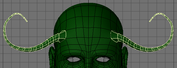
Symmetrical Editing
Operations on the positive side of the X axis also inversely affect the negative side of the X axis. When this mode is active, your object is theoretically split in half at X=0.Generally, you should perform all of your edits on the positive side of the X axis when using Symmetry. Using the negative side may lead to unpredictable results.

If you get unpredictable results, make sure the negative-side geometry is exactly the mirror of the positive-side geometry with X=0 as the center point. If the negative-side geometry is the slightest bit off, it will not be affected. Generally speaking, this mode was meant to be used where the geometry to the left and the one to the right of X=0 mirror each other. (However, all of the geometry does not need to be a mirror image, only the portion you want to work on symmetrically.)
The Fit Selected command (Shift A) respects symmetry. If both sides of an object are selected and Symmetry is active, then only one-half of the selection is used to compute the fit.
Symmetrical Selection
When you select polygons/points on the positive X axis and Symmetry Mode (Symmetry button) is active, polygons/points/edges on the negative X axis are also selected (or deselected).
Polygons/points/edges must be exactly opposite each other on the positive and negative sides of the X axis for this command to work properly.
Symmetrical Modeling: Many of the Modeling tools will work in Symmetry mode. Most of the Modify menu tools work fine. Others such as bevel or smooth shift also work. Some tools such as Bandsaw do not work in Symmetry mode. In such a case you may have to use the tool on one side then use the Mirror tool to make sure the changes are done on both sides of the X Axis.
Surface: Change Surface
(default keyboard shortcut Q)
The Change Surface command (Located at the Bottom of Modeler’s Interface) will bring up the Change Surface dialog to set the surface name and basic attributes for the selected polygons.
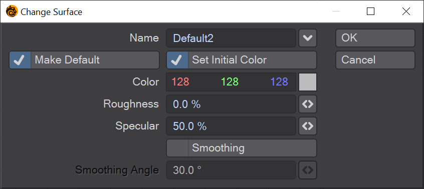
- Name - This defines the surface name of the selected polygons. The Pop-Up menu will let you choose from existing surfaces.
- Make Default - Selecting this option will assign this surface to any geometry created after the surface is made.
- Set Initial Color - This option determines whether or not you can set basic attributes for your surface.
- Color - Color is probably the most obvious surface parameter. It doesn’t take much experience to know that if we want something to look like a banana, we need to make it yellow, right? However, since you are dealing with a 24-bit color palette and, thus, over 16 million colors, there are probably thousands of shades of yellow. Moreover, other settings, such as Roughness, can have a dramatic effect on the final rendered color.
- Roughness - Roughness is the amount of light scattered by a surface, rather than returned directly to the camera. A high level scatters a lot of light, making the surface appears matte. A low level reflects most of the light, making the surface darker, but more polished.
- Specular - Specularity is a more accurate way of saying reflection. It occurs on the surface of smooth or shiny objects. High Specular levels are commonly used on glass spheres, chrome bumpers, and so on. How the surface reflects tells the observer if the surface is dull, smooth, shiny, hard, or even metallic.
- Smoothing - Smoothing causes objects to appear to have smoothly rounded surfaces even though the object is composed of flat-faced polygons. To do this, LightWave uses a technique known as phong shading. If the edges of two smooth-shaded polygons share vertices (points), they appear as one continuous, curved surface. The shared edge between them is no longer visible.
VMap Shortcut
VMaps can be created using the buttons in the lower-right corner of Modeler. These are simply shortcuts to the same options that can be found in the Vertex Maps Panel (Windows> Vertex Maps Panel). Choose a Vmap Mode to work in by clicking on one of the Vmap Mode buttons (W, T, M, C, S). Select which Vmap to edit from the Vmap drop down menu located next to the Modes buttons.
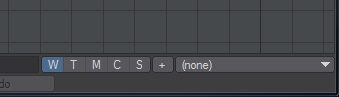
W- Weight, T- Texture, M- Morph, C- Color, S- Selection Set. The + is to add a new vmap in the mode selected.
See Vertex Maps Panel for more detail.