Editing Objects
Editing Objects
Generally, to build a 3D object, you create, combine, and modify simple shapes into more complex shapes. This is known as editing. The basic building blocks (i.e., primitives) include cubes, spheres, cylinders, and other shapes. Using tools not unlike those found in a wood or metal shop, you form a realistic representation of the envisioned object.
Have a Plan!
If you were building a desk, you would work from a sketch, a photograph, plans, or a small model of the desk you intended to build. This approach also works well for Modeling 3D objects. Having the actual shape or a representation of the object in front of you while you design is invaluable, and it will aid you in determining size, shape, angle, color, and more. Whenever possible, work from pictures or small-scale models. Picture books, magazines, blueprints, and visual dictionaries are useful companions to have nearby.
Selection Mode: Points, Edges and Polygons
The process of object editing involves manipulating points, edges and polygons. It will include selecting some portion of an existing object, choosing the operation to perform, adjusting any parameters for that operation, then carrying out the operation.
The concept of selecting is very important to Modeler. Selection is the act of specifying either the object itself, or a portion of it, that you intend to edit next. The most basic elements that you can modify include points, edges and polygons - the dots and multi-sided shapes that make up all objects. Any number of points, edges, polygons, or objects, in any combination, may be selected for a specific operation.
Everything in a layer is considered selected when nothing is selected.
When selecting and unselecting, make sure that no Modeling tool is currently active. You can usually tell if a tool is active based on the mouse pointer. You can quickly deactivate any tool by pressing the Spacebar (or RETURN); however, if no tool was active, you will change the edit mode.
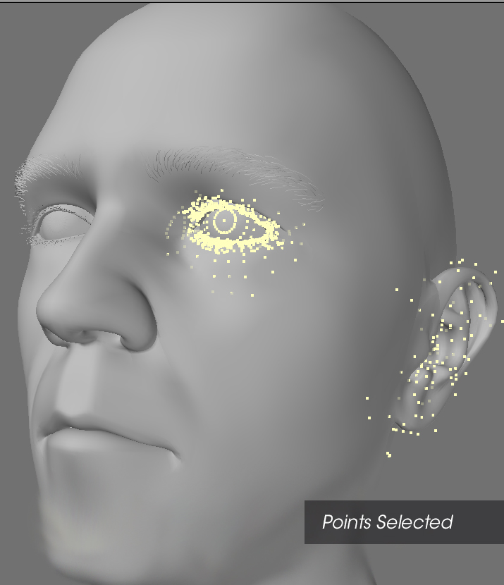
Point Selection
Points generally appear in two ways on-screen, selected and unselected. Selected points are highlighted, while unselected points remain small dots.
To select points:
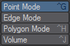
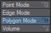
- Use Point Selection mode (Point button or Ctrl +G ). The Mode Selection buttons are located at the left of the screen under the top menu group.
- Drag your LMB over points in an object and then release the mouse button to select those points.
Once you have selected points and released the mouse button, you cannot select additional points in the same manner. You will need to hold down Shift to continue selecting or use the MMB.
If you know the number of points you want to select, check the information display above the Point (Selection mode) button. It shows you the number of selected items.
To add more points to a selection:
Hold the Shift key while you select with your LMB to add points to the existing selection or just click your MMB.
To lasso a group of points:
With the RMB , drag out a circle around points to select a group. As you might expect, you can add more points to a selection by holding the Shift key and dragging out a circle around the additional points you wish to select.
To deselect points:
If selected points exist (and you have released the mouse button), dragging over them with your LMB will deselect them. You can also use the lasso by dragging with your RMB.
To deselect all points:
Click in any non-active (i.e., not a button) area on the toolbar to deselect all points. You can also use the Drop Current Tool command (/). Also, clicking on the number of selected points in the Selection Counter information display above the Point (Selection Mode) button will deselect all selected points.
There is an option in Modeler Display Options to double-click (off geometry, anywhere in the viewport) to drop the selection. The last selection can be restored by hitting the Drop/Restore Selection button or using the default keyboard shortcut of /.
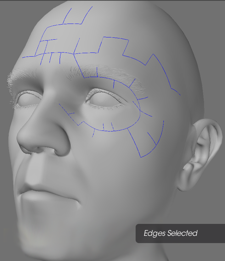
Edge Selection
Edges generally appear in two ways on-screen, selected and deselected. A selected edge will appear highlighted with outlines in yellow (default). You will see that selecting edges is very similar to selecting points or polygons.
To select edges in a viewport:
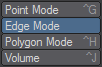
- Use Edge selection mode . The Mode Selection buttons are located at the left of the screen under the top menu group.
- If you are using a viewport set to a non-shaded Rendering Style (Display Options), like wireframe, drag your LMB over the edges and then release the mouse button.
Once you have selected edges and released the mouse button, you cannot select additional edges in the same manner.
To add more edges to a selection:
Hold the Shift key while you select with LMB to add more edges to the existing selection or just click your MMB.
To lasso a group of edges:
With the RMB, drag out a circle around edges to select a group. Only the edges located completely within the outline are selected. Of course, you can add more edges to a selection by holding the Shift key and then drag out a new circle around the edges you wish to add to the selection.
To deselect edges:
If selected edges exist (and you have released the mouse button), dragging over them with your LMB will deselect them. You can also use the lasso by dragging with your RMB.
To deselect all edges:
Click in any non-active (i.e., not a button) area on the toolbar to unselect all edgess. You can also use the Drop Current Tool command (/). Also, clicking on the number of selected edges in the Selection Counter information display above the Point (Selection Mode) button will deselect all selected edges.
There is an option in Modeler Display Options to double-click (off geometry, anywhere in the viewport) to drop the selection. The last selection can be restored by hitting the Drop/Restore Selection button or using the default keyboard shortcut of /.
Edges are always part of a polygon. Cutting, or otherwise deleting or hiding, an edge will also remove the associated polygon.
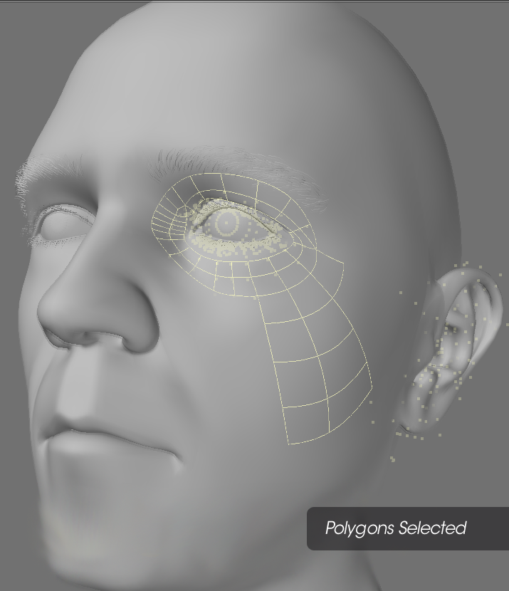
Polygon Selection
Polygons generally appear in two ways on-screen, selected and deselected. A selected polygon will appear highlighted with outlines in yellow (default). You will see that selecting polygons is very similar to selecting points and edges.
To select polygons in a viewport:
- Use Polygon selection mode (Ctrl+ H ). The Mode Selection buttons are located at the left of the screen under the top menu group.
- If you are using a viewport set to a non-shaded Rendering Style (Display Options), like wireframe, drag your LMB over the edge of polygons and then release the mouse button. This selects polygons that share that edge. With a shaded rendering style like Texture or Smooth Shade, you can click directly on the polygon’s face.
As polygons become selected, they will become highlighted and you will see a dotted line extending out of the face of the polygon and perpendicular to that polygon (The Normal display option must be active.). This dotted line is also referred to as the normal of the polygon or surface. The normal line indicates which side of a polygon has a face (the surface of the polygon you can see) or which direction the polygon is facing. In LightWave polygons by default have only one face. This means if you rotate a polygon the other side will not be visible because it is not double sided.
Once you have selected polygons and released the mouse button, you cannot select additional polygons in the same manner.
If you know the number of polygons you want to select, check the information display above the Point Selection Mode button. It shows you the number of selected items.
To add more polygons to a selection:
Hold the Shift key while you select with LMB to add more polygons to the existing selection or just click your MMB.To lasso a group of polygons:
With the RMB, drag out a circle around polygons to select a group. Only the polygons located completely within the outline are selected. Of course, you can add more polygons to a selection by holding the Shift key and then dragging out a new circle around the polygons you wish to add to the selection.
To deselect polygons:
If selected polygons exist (and you have released the mouse button), dragging over them with your LMB will deselect them. You can also use the lasso by dragging with your RMB.
Selecting a group of polygons and then deselecting the ones you don’t want is often the only way to select the ones you do want.
To deselect all polygons:
Click in any non-active (i.e., not a button) area on the toolbar to unselect all polygons. You can also use the Drop Current Tool command (/). Also, clicking on the number of selected polygons in the Selection Counter information display above the Point (Selection Mode) button will deselect all selected polygons.
There is an option in Modeler Display Options to double-click (off geometry, anywhere in the viewport) to drop the selection. The last selection can be restored by hitting the Drop/Restore Selection button or using the default keyboard shortcut of /.
Selection with In-line Points/Polygons/Edges
If there are points/polygons/edges in-line (on top of each other) in a viewport using a non-shaded rendering style (i.e., Wireframe), you select all of the points/polygons/edges when you select with your mouse. However, shaded viewports respect polygons facing away from you and those obscured by other polygons. Thus, you can select by clicking on a polygon’s face without worrying about what’s behind or on the other side. You can change the Rendering Style from the pop-up menu on the viewport titlebar or on the Viewport Tab of the Display Options Panel.
Symmetrical Selection
When you select polygons/points/edges on the positive X axis and Symmetry mode (Symmetry button) is active, polygons/points/edges on the negative X axis are also selected (or deselected). Polygons/points/edges must be exactly opposite each other on the positive and negative sides of the X axis for this command to work properly.
Symmetry also affects polygon editing.
- Sel Entire Surface - Selects all the polygons making up the surfaces of the polygons that are currently selected.
- Sel Entire Part - Selects all the polygons making up the parts of the polygons that are currently selected.
- Select Path - Selects a shortest path (there can be multiple) between two elements. The selected elements can be of any type (vertex, edge, polygon).
- Select Outline Points - Selects the outer points of a selected set of polygons.
- Select Outline Edges - Selects the outer edges of a selected set of polygons.
- Edge Selection
- Loop Expand - Expands an edge selection along an edge loop.
- Loop Contract - Shrinks an edge selection along an edge loop.