Modeler User Preferences
Modeler has two Options windows, General and Display. It also uses the same Keyboard Shortcut, Configure Menus and Edit Plugins windows as Layout.
General Options
(default keyboard shortcut O)
You can access the General Options Panel by choosing Edit > General Options.
General Tab

- Content Directory - The Content Directory is a central file path for loading objects, images, and scenes. Note that this setting is shared by all LightWave applications.
- Preset Shelf - The Edit Custom Locations button here opens the Custom Locations Editor. There you can add new locations where you've either already got presets or you'd like to create new ones. Flagging a location as the Default Save, means that things such as the Surface Editor, when it requests a new preset to be added. That preset will go to that Default location.
Default Polygon Type - Some operations in Modeler create many polygons in one operation. As such, the computer must decide whether to generate triangles (three-point polygons) or quadrangles (four-point polygons), depending on the shape’s requirements.
To force the computer to use Triangles or Quadrangles, select either for the Polygon setting. Choose Automatic to let the computer create the most appropriate polygon type for each given operation.
To create optimal objects, your goal is to keep the polygon count down. They will load and render faster than bloated objects, with no visible difference. As such, Quadrangles is the suggested setting for most cases. This lets you manually choose the areas that require triangles
Flatness Limit - The Flatness Limit setting determines whether Modeler regards a polygon as planar or not. Note that a non-flat polygon considered planar according to this setting can still cause rendering errors.
All polygons must have a surface name. When geometry is created, polygons are given the default surface name of Default. You can change the default name by changing the Surface field. This will affect only geometry created from that point on, however. Use the pop-up to the right of the field to select from existing surface names.When you create a surface using the Change Surface dialog (Detail > Polygons > Surface), the option (Make Default) automatically sets the default surface name.
- Curve Divisions - The Curve Divisions setting determines how smoothly a curve (e.g., spline curves, text, etc.) should be interpolated. The finer the setting, the greater the number of polygons used, and the smoother the resulting curve division.
SubPatch Divisions - When a SubPatch object is frozen with the Freeze command ( Ctrl D), it is converted into a polygonal object. The Patch Division setting determines the level of detail used in the resulting object. The number entered in the Patch Division field must be 1 or greater and is restricted to whole numbers.
The number of polygons per SubPatch surface will be equal to the square of the Patch Division number. For example, if set to 4, each SubPatch surface will be converted into 16 polygons arranged in a 4 by 4 array. A setting of 2 would result in 4 polygons arranged in a 2 by 2 array. For Catmull-Clark patches, every level of Catmull-Clark subdivision quadruples the number of polygons.
The higher the setting, the higher the number of polygons used. Because of LightWave’s surface smoothing capabilities, you can often get away with a setting of 2 and sometimes even 1, which will keep the polygon count of your objects to a minimum.Setting this value too high with heavy-polygon SubPatch models can cause the performance of Modeler to degrade. If Modeler appears to be running sluggishly when working with SubPatch models, lower this value to help improve performance.- Metaball Resolution - This setting determines the amount of detail used to display metaballs.
- Symmetry Tolerance - Sets the amount matching elements can differ on opposite sides of the symmetry for symmetry to work.
- Image Cache Maximum - If enabled, sets the amount of caching available for images in megabytes.
OBJ Tab
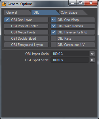
The OBJ tab contains options for importing and exporting OBJ file objects.
- OBJ One Layer - imports the object as a single layer.
- OBJ One VMap - imports the object with a single vertex map.
- OBJ Pivot at Center - creates the pivot of the object at the center of the object.
- OBJ Write Normals - writes the normals associated with the object when saved.
- OBJ Merge Points - merges points sharing the same space.
- OBJ Reverse Ka & Kd - Reverses Ambient Occlusion and Diffuse channels.
- OBJ Double Sided - Creates double-sided geometry.
- OBJ Parts - Keeps LightWave Part Polygon tags.
- OBJ Foreground Layers - Only saves layers marked as foreground to OBJ.
- OBJ Continuous UV - UVs have shared points rather than duplicated.
- OBJ Import Scale - sets the scale of an object when it is imported.
- OBJ Export Scale - sets the scale of the object when it is exported.
Color Space Tab
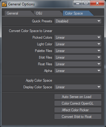
Color space conversion is performed in four places in LightWave.
- On loading, an image can be converted from its native color space format to linear.
- When sent to the Image Viewer, an image can be converted from linear to another color space.
- When saved from the renderer, an image can be converted from linear to another color space.
- When picked from the Color Picker, a color can be converted from and then to linear color space.
The color space defaults are set up on the Layout Preferences panel.When an option is selected in the pop-up it becomes the current item for that selection.
Color tables are added to the selections, as if they were built-in.
A color table can be loaded by using Load Table from the pop-up. The color tablesare stored in the project directory, in a directory called Color Tables.
In the Image Editor, there is a check box, Treat as Alpha. This means use the alpha channel from the Preferences Default setting, not the alpha channel from the color space in the Image Editor. This is an override on the alpha color space selected in the Image Editor.
One can set the color correction for the Viewer files with palettes, 8-bit files, floating point files, alpha channel and the color picker from the preference default panel and the Modeler General Options panel.
When an image is loaded, if the file setting for that image is set to default, then an attempt is made to look at the metadata setting for that image. If the metadata settings have the color space the image was saved in, then it is used. For example, jpegs have metadata setting for sRGB and Adobe 1998 linear format.
The built-in color spaces are:
- Linear, LightWave linear color space.
- sRGB, Standard RGB color space.
- rec709, BT.709, HDTV
- Cineon, Eastman Kodak Co.
The color lookup tables come in two formats:
- LightWave color table format.
- 3D LUT format.
LightWave color table format is as follows:
Code:
EGA
17, -0.5, 1.5
; Convert on load.
-0.5, -0.5, -0.5, -0.5
-0.375, -0.375, -0.375, -0.375
-0.25, -0.25, -0.25, -0.25
-0.125, -0.125, -0.125, -0.125
0.0, 0.0, 0.0, 0.0
0.125, 0.125, 0.125, 0.125
0.25, 0.25, 0.25, 0.25
0.375, 0.375, 0.375, 0.375
0.5, 0.5, 0.5, 0.5
0.625, 0.625, 0.625, 0.625
0.75, 0.75, 0.75, 0.75
0.875, 0.875, 0.875, 0.875
1.0, 1.0, 1.0, 1.0
1.125, 1.125, 1.125, 1.125
1.25, 1.25, 1.25, 1.25
1.375, 1.375, 1.375, 1.375
1.5, 1.5, 1.5, 1.5
; Convert on save.
-0.5, -0.5, -0.5, -0.5
-0.375, -0.375, -0.375, -0.375
-0.25, -0.25, -0.25, -0.25
-0.125, -0.125, -0.125, -0.125
0.0, 0.0, 0.0, 0.0
0.125, 0.125, 0.125, 0.125
0.25, 0.25, 0.25, 0.25
0.375, 0.375, 0.375, 0.375
0.5, 0.5, 0.5, 0.5
0.625, 0.625, 0.625, 0.625
0.75, 0.75, 0.75, 0.75
0.875, 0.875, 0.875, 0.875
1.0, 1.0, 1.0, 1.0
1.125, 1.125, 1.125, 1.125
1.25, 1.25, 1.25, 1.25
1.375, 1.375, 1.375, 1.375
1.5, 1.5, 1.5, 1.5
Where:
EGAis the name of the color space that appears in the pop-up.17is the number of entries in the color table.-0.5is the lower range of the look-up table (black).1.5is the upper range of the look-up table (white).-0.5, -0.5, -0.5, -0.5are the rgba values for the table entry.- Blank lines and lines beginning with comments, are skipped over.
- 3D LUT format tables are read in and a reverse lookup table is made. The name of the color space is the name of the file on the pop-up.
Auto Sense on Loaddetects the Color Space settings and uses those when a scene is loaded.Color Correct OpenGLwill color correct the OpenGL viewports.
Display Options
(default keyboard shortcut D)
Modeler’s interface is highly configurable allowing to tailor it to your specific needs. You can change the arrangement of viewports as well as change the display characteristics for each viewport independently. Choose Edit > Display Options to bring up the Display Options Panel.
Layout Tab

Layout options control the global arrangement of the viewports, the number of viewports and some other Global Display settings. Use the Presets pop-up menu to quickly set common layout configurations (Quad is the default setting). Selecting a Preset will affect the Layout setting, as well as settings on the Viewports Tab.
If you want to set up your own custom layout, make a selection from the Layout pop-up menu. The icon to the left of the description will give you an idea of how the viewports will be arranged. Later, you will see that you have total control over what is in each viewport. In fact, each Layout option will remember the Viewport settings as they were the last time that Layout option was used.

- Perspective Amount - The amount of perspective in the perspective view can be varied by changing the Perspective Amount slider on the Layout Tab. You can go from a very wide-angle to a flat nearly orthogonal view. The setting is global and affects all the perspective views the same way.
- Background Color - Use the Background Color selector to change the color that appears in the background for viewports using a shaded display.
- Default Sketch Color - Use the Default Sketch Color setting to change the color that the wireframe will appear in the various view modes. You can always change the Wireframe color on polygons using the Sketch Color tool located under the Detail Tab.
- Selection Color Options - Use the Selection Color Palette for editing Point > Edge > Polygons when selected. Other options include changing the color for Normals and the color of active Tools.
- Tool Color - Specifies the color for tool gizmos and Syncmesh tool text.
- HUD Color - Specifies the color for the viewport surround when editing morphs.
- HUD Opacity - Defines the strength of the color used for the HUD.
- Fixed Normal Length - Change the length of the normal here.
Show Options
The various Show Visibility options let you independently set what you want to see globally in your viewports.
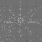
- Show Points - Points appear as small dots
Left: Show Points On, Right: Show Points Off
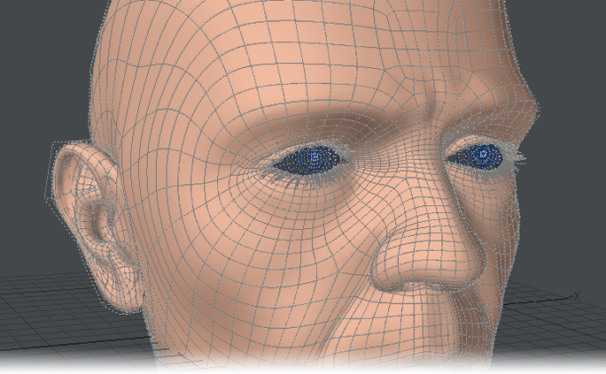
- Show Surfaces - Surfaces are the polygon (or SubPatch) surfaces

Left: Show Surfaces On, Right: Show Surfaces Off
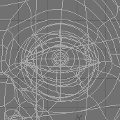
- Show Cages - A cage is the outline that connects all of the control points when you edit a SubPatch object
Left: Show Cages On, Right: Show Cages Off
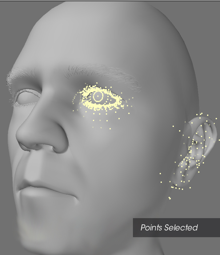
- Show Point Selection - When points are selected they appear highlighted if this option is selected
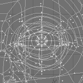
- Show Guides - Guides are the dotted-lines that extend from the surface (patch vertex) to the control points on the cage (if visible) when you edit a SubPatch object
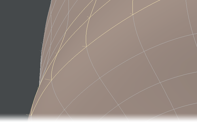
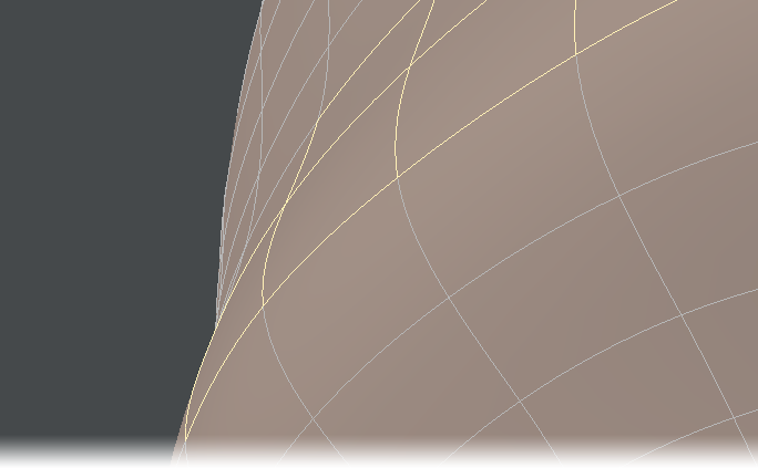
Left: Guides on, Right: Guides off
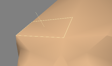
- Show Normals - Normals are dotted lines that extend perpendicularly from selected (planar) polygons and indicate the direction a polygon is facing
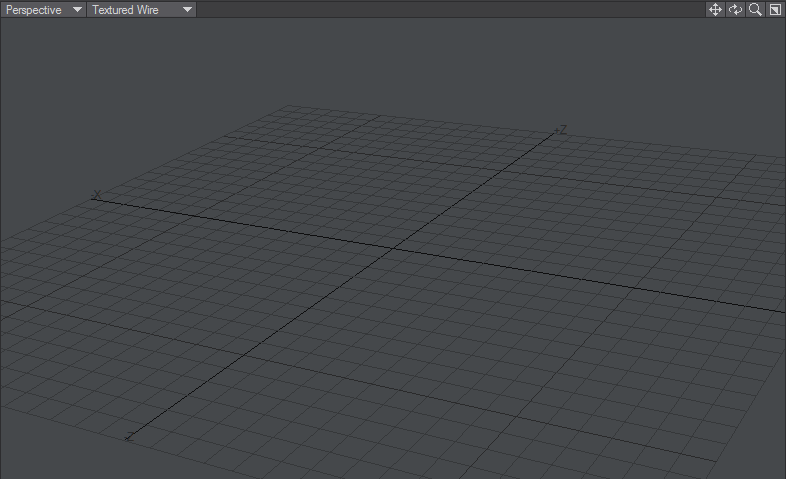
- Show Origin - This option will show the 0 axis in the viewports. For the perspective view, only the X and Z axis are shown.
- Show Grid - The grid is the background reference grid
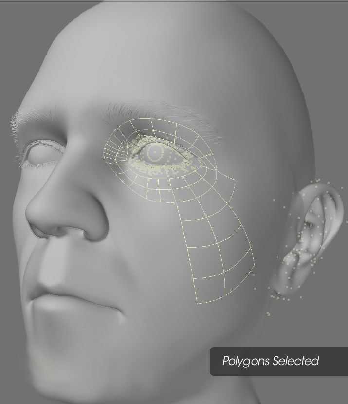
- Show Polygon Selection - When polygons are selected they appear highlighted if this option is selected
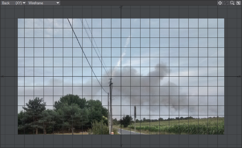
- Show Backdrop - A Backdrop is an image loaded for viewports on the Backdrop Tab. These images can be useful as Modeling reference
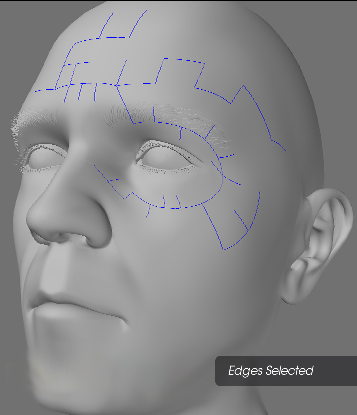
- Show Edge Selection - When edges are selected they appear highlighted if this option is selected.
GL Tab

- Texture Resolution - The Texture Resolution setting determines the resolution to use for displaying textures in viewports that have their Rendering Style set to Texture. Higher settings increase the detail of image textures displayed in viewports, but increase memory usage and display refreshing time.
- Shading Method - Choose between MultiTexture, GLSL and PBRGLSL Shaders. Multi-texture shaders are simpler and intended for graphics cards that are less capable. GLSL is faster and shows more texture capabilities for modern cards. PBRGLSL shaders are the most modern and will show more accurate detail on capable videocards.
- Transparency Sorting - There are three options to choose from:
- SortByObject - sorting the objects by their distance from the camera - fast method
- SortByPolygon - sorting polygons by their distance from the camera - slowest method
- AlphaClipping - uses the alpha value of a texture in the transparency channel to determine transparency - fastest method
SortByObject is the default setting and will be the fastest in most cases.
- Geometry Acceleration - Determines how the graphics card displays OpenGL. Streaming renders the mesh immediately to screen, using the lowest amount of memory at the cost of speed. It also won't show normal maps. Buffered(VBO) will attempt to store the geometry in graphics card memory, allowing for the highest speed, at the cost of memory. In cases where the mesh or shading changes with every frame no caching is possible, a fallback to the Streaming method will result, for example with animated meshes and reflection maps. Smooth shaded geometry will benefit the most from the Buffered(VBO) mode. If the mesh is buffered in graphics card memory the performance you will get as much performance as your graphics card can give you.
- Pixel Blending - Texture filtering
- Mipmapping - Mipmapping is similar to what is used in today’s games to avoid graininess of textures in a distance or at a flat angle. Basically lower- res versions of the texture are generated in realtime and blended in. This feature is supported in hardware by most of today’s graphics cards. This feature also works if Mutitexturing is turned off. Please note however that due to the nature of this filtering method, low-resolution textures may appear a bit blurry.
- Reflections - Switches reflections on and off. Only applies to image-based reflection maps.
- Transparency - Switches transparency on and off.
- Multitexture - Uses LightWave's original OpenGL drawing method. If your meshes are very heavy using this instead of GLSL is advised.
- Frame Buffer Object - accelerates object drawing slightly.
- Color Channel - De- /Activates the display of textures in the Color Channel if Multi-texturing is on.
- Diffuse Channel - De- /Activates the display of textures in the Diffuse Channel if Multi-texturing is on.
- Transparency Channel - De- /Activates the display of textures in the Transparency Channel if Multi-texturing is on.
- Luminosity Channel - De- /Activates the display of textures in the Luminosity Channel if Multi-texturing is on.
- Specularity Channel - Will show the specularity surface setting in PBRGLSL mode.
- NormalMap Channel - Will show normal map in PBRGLSL mode
- Legacy OpenGL - Uses the pre-LightWave [8] OpenGL drawing routines
Viewports Tab

Viewport options let you change how objects are displayed in each viewport. To change the settings for a viewport, first select it using the Viewport buttons.
Use the Presets pop-up menu to quickly set the options on this tab for the selected viewport region. The selections are listed by view types, but will affect all of the settings on this tab.
The View Type pop-up menu determines the editing axes you want to use for the selected region.
For the Orthogonal settings, the names generally indicate the viewing perspective. Back (XY), for example, lets you edit along the X and Y axes. This means you are looking along the Z axis.
Since it is called Back, that means your perspective is from the back (i.e., negative side) of the Z axis, looking toward the positive side. UV Texture is entirely different - it is not used as a Modeling viewport but for adjusting UV texture maps.
Perspective
You may edit in a Perspective viewport, just as you would in any other, but you may also rotate your view perspective. This is Modeler’s virtual trackball, which enables you to rotate the object without affecting its orientation in the other three edit windows. It effectively provides you with three axes of rotation. While holding down the Alt key, you can perform these actions:
- Rotate around the X axis (pitch) by dragging up or down directly across the vertical center of the viewport
- Rotate around the Y axis (heading) by dragging left or right directly across the horizontal center of the viewport.
- Rotate around the Z axis (bank) by dragging to the left or right around the perimeter
If the title bars are visible, you can drag the rotate drag button with your LMB to rotate. If you use the RMB, the viewport will rotate around its perpendicular axis. Holding the Ctrl key (or using your MMB) will cause rotations to snap to 15-degree increments.
- Rendering Style - The Rendering Style pop-up menu determines the style of display you want to use for the selected region:
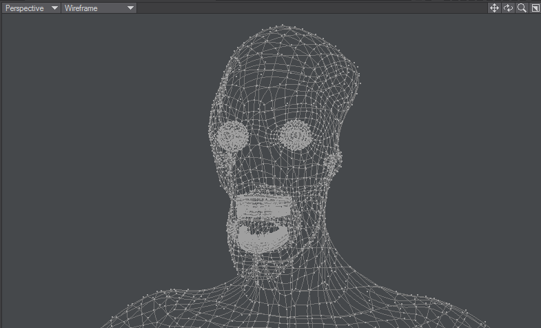
- Wireframe - Although the Wireframe is arguably the most limited display mode, it is the most commonly used Rendering Style because of its ease in viewing, selecting, and unselecting points and polygons.
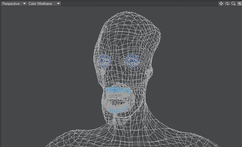
- Color Wireframe - This is nearly the same as Wireframe, except the polygon edges are drawn using their Sketch color (Detail > Polygons > Sketch Color).
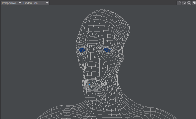
- Hidden Line - Hidden Line shows an object’s Front Face polygons in wireframe view.
- Sketch - Sketch shows an object in a combined wireframe and flat-shaded view. All polygon edges are drawn, but faces are also visible. This mode does not account for Surface settings, however. The polygon edges are always drawn in white and faces are grey. Background layers are visible.
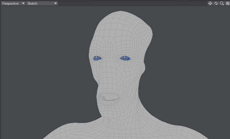
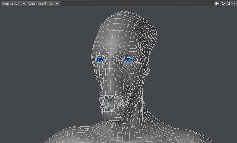
You can change the polygon shading color in this mode by choosing Detail > Polygons > Sketch Color. - Wireframe Shade - Wireframe Shade is a smooth-shaded mode that overlays the wireframe lines.
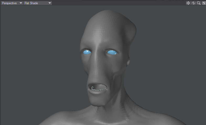
- Flat Shade - In Flat Shade mode, the object is shown as a flat-shaded solid. This mode supports some Surface settings, but not smoothing.
- Smooth Shade - Smooth Shade is a smooth-shaded mode that supports some Surface settings, such as Color, Diffusion, Specularity, Glossiness, Smoothing, and Double-sided.

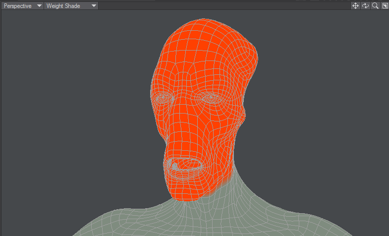
- Weight Shade - Weight Shade provides visual feedback for editing Weight Maps.
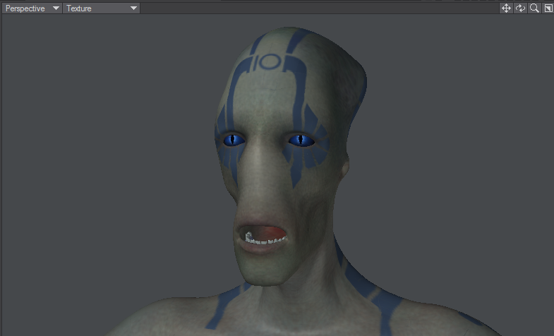
- Texture - Texture is similar to Smooth Shade, but it also shows images mapped to surfaces.
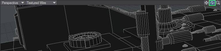
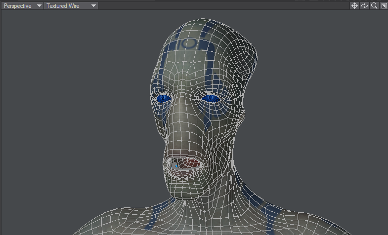
- Textured Wire - Textured Wire is similar to Texture, but it also shows wireframes on the surfaces.
- Wireframe - Although the Wireframe is arguably the most limited display mode, it is the most commonly used Rendering Style because of its ease in viewing, selecting, and unselecting points and polygons.
- Upright Rotation - The Upright Rotation pop-up menu lets you rotate a viewport clockwise by 0, 90, 180, and 270 degrees to accommodate imported objects from applications that may use other axes as up, or for exporting to them, for that matter.
Titlebar Shortcuts
You can change the View Type and Rendering Style of a viewport without going to the Display Options Panel by using the pop-up menus on the title bar. Clicking on the left-most pop-up allows you to choose which View Type you want to be in and will then display it. The pop-up menu just to its right lets you choose the Rendering Style.
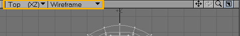
Note that if you have UV Texture selected as the View Type, the Rendering Style pop-up menu will instead list all loaded images. Select one to load it into the backdrop of that viewport.
Independent Options
The Independent options let you make certain viewport characteristics independent from other viewports. Changes to the selected characteristic do not affect it in other viewports and vice versa. For example, if a viewport uses Independent Zoom, zooming in it does not affect the zoom of other viewports. You must have your pointer over the viewport to affect an independent viewport. Independent Rotation is only applicable to perspective views. Normally, it is enabled. If you have multiple perspective views and this option disabled, they will move in unison when you rotate a view.
Independent Visibility
The lower portion of the panel contains the independent visibility options. You can individually select which visibility options are independent. To use them, you must also activate the Independent Visibility option. This option lets you quickly enable/disable this feature without losing the state of each setting.
Backdrop Tab

On the Backdrop Tab, you can add full-color backdrop images that act as reference guides when you build objects. They let you model much like tracing a picture using tracing paper. To use backdrops, select the Viewport and the desired image from the Image pop-up menu.
From the Presets pop-up menu, you can save the settings for the selected Viewport to a file by choosing Save Current Backdrop. You can load this file later using Load Backdrop for any selected Viewport. You can also save the settings for all viewports by choosing Save All Backdrops. When this file is loaded later - using Load Backdrop - the individual Viewport settings are restored.
Use the Image drop down menu to select from the loaded images or choose (Load Image) to bypass the Image Editor and load a new image into Modeler and automatically select it for the current viewport.
You can also adjust Brightness and Contrast. Use the sliders to adjust the settings. You can invert the colors by activating the Invert option. If you want to blend pixels for close-up work, activate the Pixel Blend option. Image Resolution determines the accuracy of the displayed image.
Aspect and Video images
The two Center and Size input fields are horizontal (top field) and vertical (lower field). Clicking Automatic Size will enter values that fit the defined image into an implied bounding box that surrounds visible geometry.
If you activate the Fixed Aspect Ratio option, you can enter a frame aspect ratio in the input field. Then, you only need to specify a horizontal size - the vertical size is computed automatically. If your images originated from video, you need to account for the pixel aspect ratio, since video pixels are not square like computer pixels. For example, a D1 NTSC image is 720 x 486 pixels; however, the frame aspect ratio is not 1.48 (720/486) as you might expect. The width of a D1 NTSC pixel is 90 percent of the width, that is, a pixel aspect ratio of .9. As such, the true frame aspect ratio is 1.333 (720/486*.9).
If you do not account for this difference, your models may appear slightly stretched when ultimately viewed on video. A way to fix this is to scale the object after the fact.
Interface Tab

The Alert Level affects how error, warning and informational messages are displayed. The Toolbar Position setting determines if the main toolbar appears on the Left or Right side. Activate Hide Toolbar to make it hidden and maximize your screen real estate. Alt +F2 will hide (and more importantly, Unhide) the Toolbar as well.
Toolbar On/Toolbar Off
The Viewport Titles option turns the titlebars, which appear above each viewport, on or off.

Toolbar On, Viewport Titles Off
Use the Input Device buttons to select the type of input device you are using.
New to LightWave 2015, you can optionally set Mouse Wheel Zoom to enable the use of the mouse scroll wheel to zoom in and out of a viewport. As with using the Ctrl Alt shortcut, the view will zoom based on your mouse pointer’s location.
The next option is for Double-click Deselect, also new to 2015. This gives you the possibility to double-click on any empty space in the Modeler interface to deselect all selected Points, Edges or Polygons. You will still be able to use a single click in the normal deselect areas (under the menu buttons, on top of viewports, etc.) will this option is engaged.
The Fine Detail Cursor option, when active, makes your mouse pointer use the main crosshair pointer at all times instead of changing when the various tools and selection functions are used.
The File Dialog pop-up menu lets you use custom LightWave dialogs for file loading/saving. Selecting Default will use your standard system dialog.
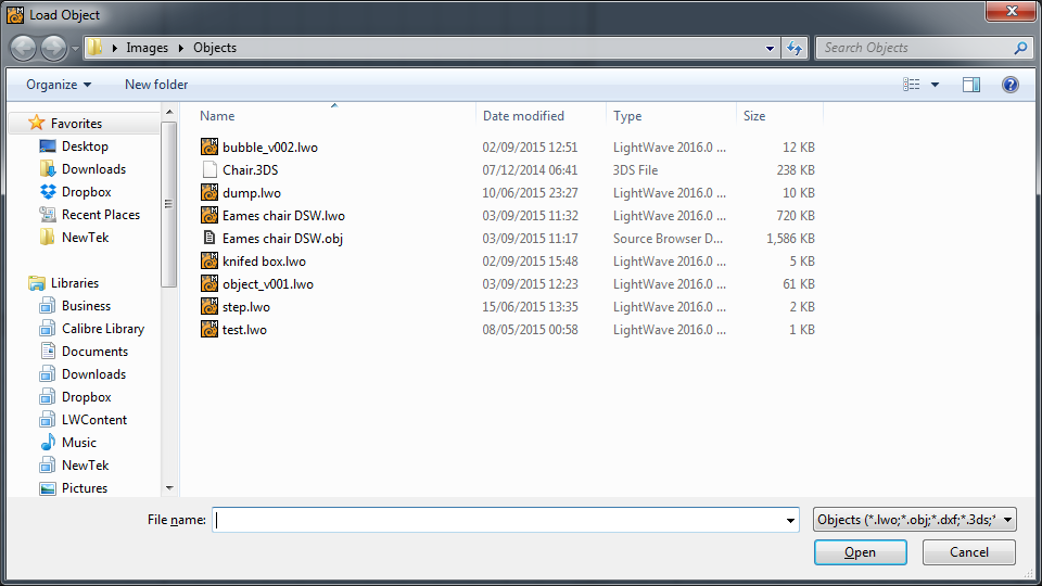
The custom File dialog provides many additional features not available with the standard system dialogs.
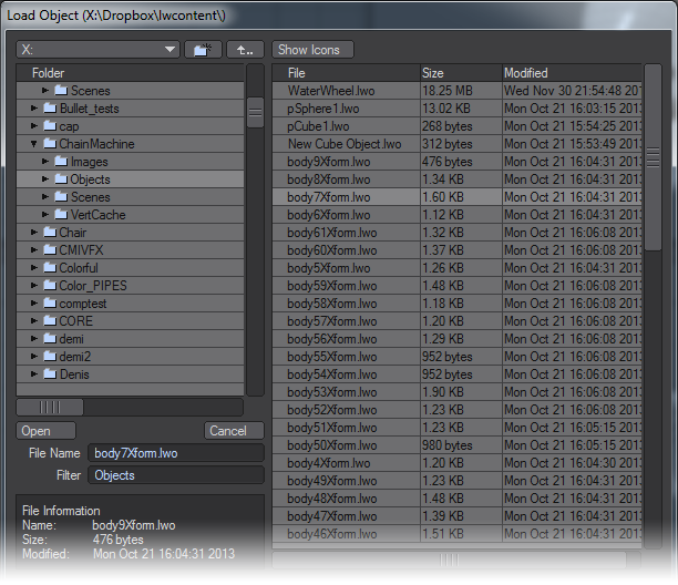
The Visual Browser - You can make the LightWave visual browser the default file dialog for Layout and/or Modeler by choosing VBFileRequester on the File Dialog pop-up menu. This appears on the Interface Tab of Modeler’s Display Options Panel (Edit > Display Options).
The Color Picker pop-up menu lets you use custom LightWave dialogs for picking colors. By default it is set to the LightWave color picker shown below, but if you wish you can choose the system color picker here.

The Color Format setting determines the scale used where the color selector appears. Integer uses values 000 to 255, Float uses .00 to 1.00 and Percentage uses 0% to 100%.
The Simple Wireframe Edges option turns off polygon offsetting for the sketch-like display modes. This may fix display problems on some video cards. The Simple Wireframe Points setting uses OpenGL’s own points for wireframe points and selected points at a user-specified size. These points can draw much faster than the standard points.
Units Tab

The Unit System determines the units of measurement that are used and displayed by the Modeler screen.
- SI - is the International System of Units (SI is the abbreviation of the French “Le Système International d’Unités”). Unit measurements in Modeler will use a base system of meters. Grid sizes and distances can be measured in megameters, kilometers, meters, millimeters, micrometers, and nanometers.
- Metric - The Metric System is the same as SI with the addition of centimeters.
- English - The English System uses miles, feet, and inches.
If you input a value that uses a different unit of measurement than that of the default, LightWave will convert it on the fly. For example, you may be using meters, but typing in “5 ft” will convert to “1.524 m.”
Default Unit - Use the Default Unit pop-up menu to set an assumed measure when none is given for distance values.
If you use a metric Unit System, you should set the Default Unit to meters.- Grid Units affects the zoom step amount but has no effect on the actual size of the object. You will likely find that 1 2.5 5 and 1 2 5 are your most commonly used Grid Unit settings.
- 1 - The grid resizes in values that begin with 1, as in 10m, 1m, 100mm, 10mm, etc.
- 1 5 - The grid resizes in values that begin with 1 or 5, as in 1m, 500mm, 100mm, 50mm, 10mm, etc.
- 1 2.5 5 - The grid resizes in values that begin with 1, 25, or 5, as in 1m, 500mm, 250mm, 100mm, 50mm, etc.
- 1 2 5 - The grid resizes in values that begin with 1, 2, or 5, as in 1m, 500mm, 200mm, 100mm, 50mm, etc.
- 1 2 - The grid resizes in values that begin with 1 or 2, as in 1m, 200mm, 100mm, 20mm, 10mm, etc.
- Grid Snap - The Grid Snap setting forces point creation and item movement to be limited to a specific increment.
- None - None deactivates grid snap, so that items move freely and are not constrained by any grid intersections.
- Standard - Standard sets the grid snap to one-tenth of the current grid size.
- Fine - Fine makes the grid snap as small as possible for the current zoom level. This will be typically two to five times smaller than using Standard.
- Fixed - Fixed lets you specify the increment of movement in the Snap Value input field. The grid will resize itself to use the value you specify.
- Time Format - The Time Format setting allows you to set the display format for time values, like the Frame Slider Label option on Layout’s General Options Tab of the Preferences Panel. If the Hub is active, Layout and Modeler settings will be kept in sync.