Bend Tool
The Bend tool (Modify > Bend) is a combination of Rotate and Shear. It will move one side of an object and rotate it at the same time, causing the entire object to bend.
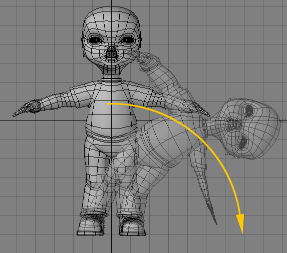
To use the Bend tool:Select the tool and drag your LMB in the direction you want the bend to occur. The initial pointer location defines the center of the rotation. The trick is to use the Bend tool in the viewport that is perpendicular to the axis of the bend. Let’s say you have a tube whose main axis is along Y. Use the Bend tool from the top or bottom view. Also, experiment with the placement of the cursor relative to the object. Activating Bend when the cursor is centerd over the object has a different effect than activating Bend with the cursor located away from the object.
The information display tells you the Angle of bending, that is, the number of degrees you bent the object. Hold the Ctrl key while dragging to constrain movement to increments of 15 degrees—this makes it much easier to bend along a single axis.
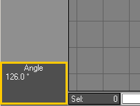
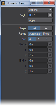
- Angle - The Angle value on the numeric panel will reflect the degrees of rotation.
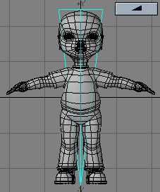
- Shape - You can quickly select between two basic falloff directions using the Shape buttons. The Shape setting determines the Area of Influence. This is shown graphically in both the numeric panel and viewport windows. You can also use the Left and Right cursor keys to change the selected Shape.
Range
The Range option determines where the Falloff’s center is located. By default, a linear falloff tool’s effect is automatically applied to the object (or selected items), 100 percent at one end and zero at the other, along the axis perpendicular to the editing viewport. This is indicated by the Range option at the bottom portion of the numeric panel, which has Automatic selected.To use the tool in the Automatic Mode via the numeric panel (by clicking the Apply button), select the perpendicular Axis. (If the axis has not been set either manually or by a previous mouse-based modify operation, the Axis setting is used to compute the falloff when you click Apply.)
- Automatic - The center is set by clicking in the viewport.
- Fixed - The center is set by entering in values in the numeric window.
Using the Automatic Range is the simplest method. Thus, if possible, model your object along one of the three axes.
Instead of using an Automatic Range, you can define a specific Fixed Range using an axis tree. This type of Range can be placed at any position and at any angle in 3D space. The effect tree looks like a pair of crossed wedges. The tool’s effect is applied along this tree with zero at its tip and 100 percent at its base (fat end) - portions of the object beyond the base are still affected 100 percent.