Fiber FX
This group is dedicated to Modeler tools for Layout’s FiberFX hair and fur system. For the Layout interface and controls see FiberFX
FiberFX Strand Modeler
There are a number of tools available in LightWave 3D Modeler for FiberFX. These tools not only allow you to build 2-point poly chain fiber guides for use with the FiberFX Pixel Filter plugin in Layout but the creation of full 3D fiber geometry, Vertex Bias maps for controlling fiber direction and auto-creation of UV maps for 3D fibers.
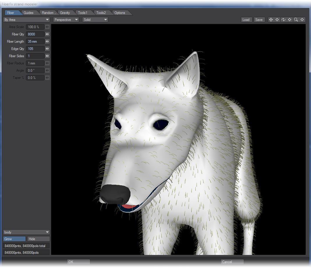
The Strand Modeler is the main part of FiberFX inside LightWave Modeler. When opened the Strand Modeler interface looks like this:
Viewport Hotkeys
The OpenGL viewport window supports many of the same hotkeys as LightWave 3D. Holding down the Alt key while dragging in the viewport rotates the view, Alt + Ctrl zooms and Alt + Shift pans the view.
The ‘a’ key auto fits and centers the object in view. The numerical keys 1 - 6 changes the viewport to show front, back, top, bottom, right and left views respectively.
Global Controls
Surface Selection & Controls
In the lower left-hand corner, you can select which surface on your model to grow your fibers on using the popup menu. You are not limited to just one surface, selecting a different surface name allows you to grow fibers with different settings on each surface in one fiber modeling session.
Once you have selected your surface, click the ‘Grow’ button, this will then add fibers to the selected surface using the current settings. Switching between surfaces allows you to edit the fibers parameters for that particular surface.
You can also click the ‘Hide’ button should you need to clean up the view while working on a particular part of your model.
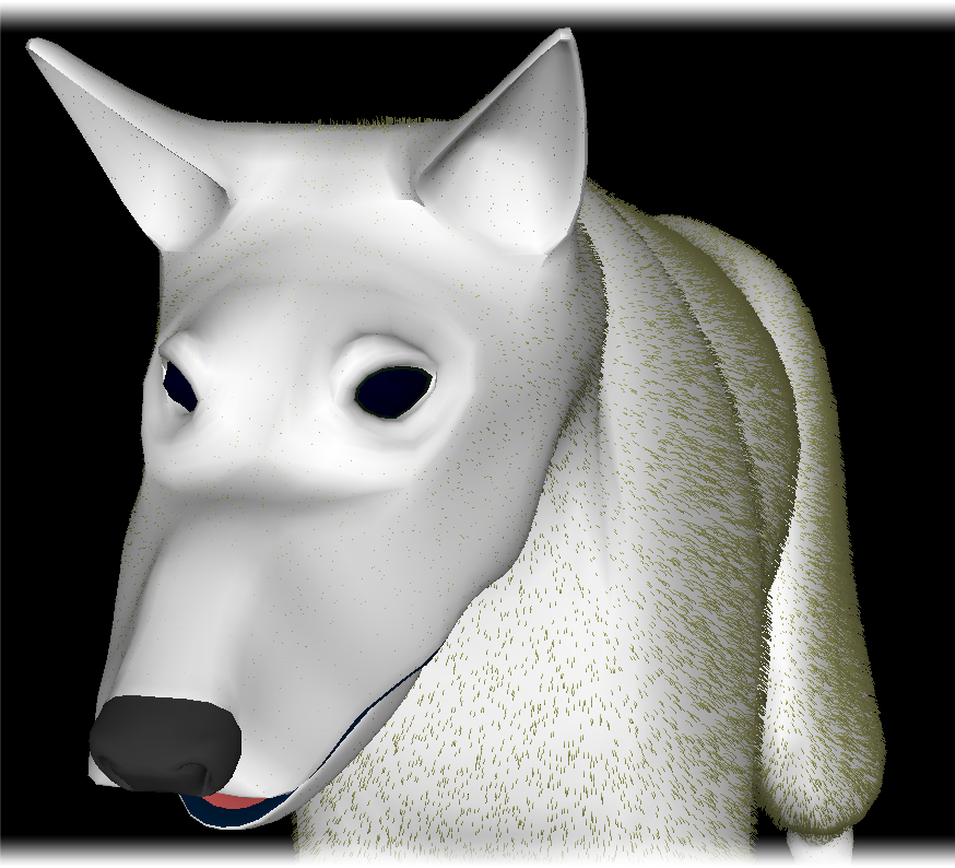
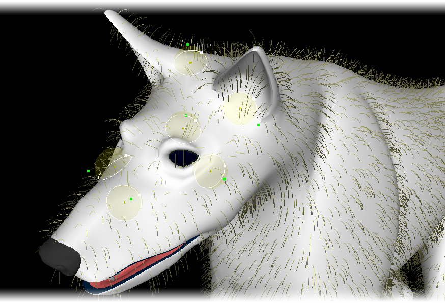
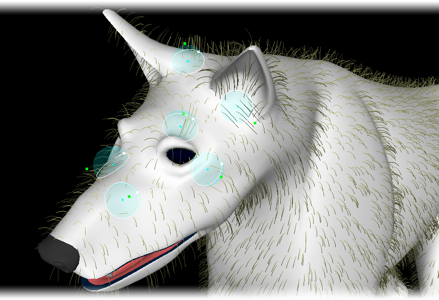
FiberFX Strand Modeler showing fibers with different parameters grown on an object.
Load / Save
If you want to save your fiber editing session for later, you can save and load using these controls (you will need to save each surface setting if you have more than one). Note, any guides you’ve added will not be saved. To store guides you must click the ‘Okay’ button to complete the session. Fibers will be created along with the guides (each in different layers). To recall your session you must first load the settings, then load the guides using the ‘Add Guides’ popup menu found under the ‘Guides’ tab.
Fiber Tab
Fiber Distribution
There are two methods for distributing fibers over your models surface, ‘By Area’ and ‘1 Per Polygon’. Both of these methods also have a ‘Scaled’ option whereby the size of the underlying polygon is taken into consideration; you can adjust this compensation by adjusting the ‘Area Scale’ property. This gives a total of four actual distribution methods.
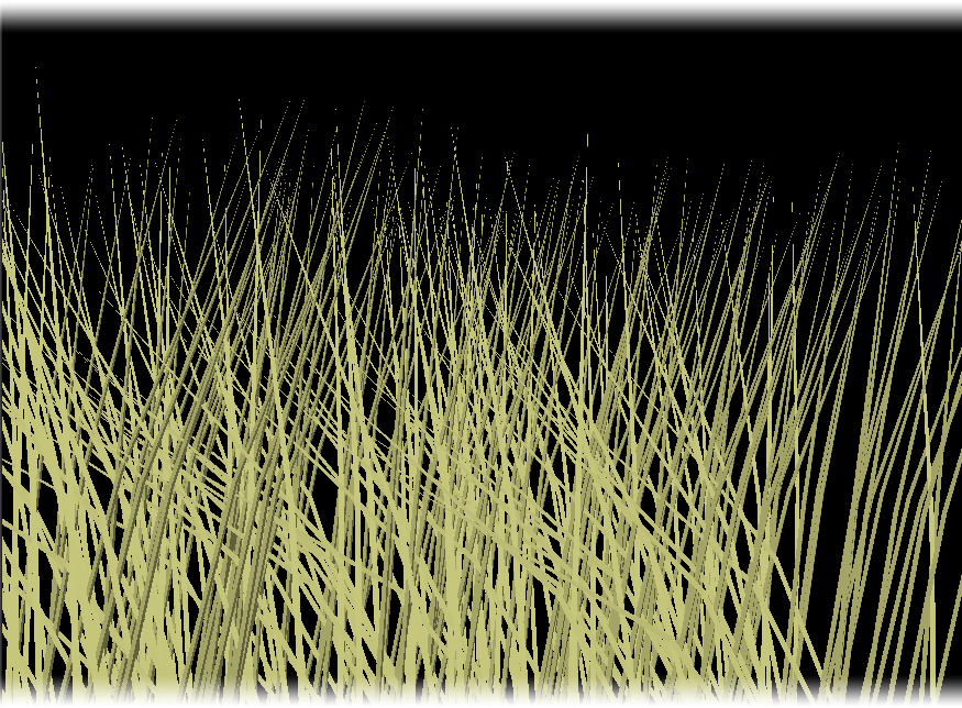
- By Area - The number are fibers in the ‘Fiber Qty’ setting are scattered across the whole surface randomly.

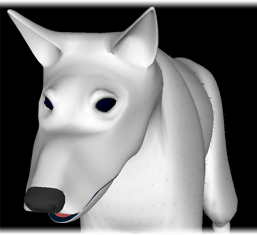
Fiber Distribution ‘By Area‘
- By Area Scaled - The number are fibers in the ‘Fiber Qty’ setting are scattered across the whole surface randomly but scales the length of the fibers according to the underlying polygon area size. This scaling can be adjusted by the ‘Area Scale’ control.
Fiber Distribution ‘By Area Scaled‘
- Per Polygon - Places one fiber at the center of each polygon on your surface, this creates a very ordered appearance. If you use these fibers as guides in the ‘FiberFX Pixel Filter’ in LightWave 3D Layout, you can create many more ‘virtual’ fibers clustered about the center of these ‘guides’, giving the appearance of more fibers.

Fiber Distribution ‘1 Per Polygon‘
- Per Polygon Scaled - Places one fiber at the center of each polygon on your surface, but scales the length of the fibers according to the underlying polygon area size. This scaling can be adjusted by the ‘Area Scale’ control.
Fiber Distribution ‘1 Per Polygon Scaled‘
- Area Scale - This setting becomes available when the fiber distribution method is set to ‘By Area Scaled‘ or ‘1 Per Polygon Scaled‘. It adjusts the percentage of scaling from the largest to the smallest polygons.
- Fiber Qty (Quantity) - Determines the number of fibers to be used in ‘By Area’ distribution mode.
- Fiber Length - Set the length of the fibers. If ‘Area Scale’ is active, this would be the length of the polygons with the largest area. Length is measured from root to tip with the fiber in an absolutely straight position.
Effects such as Curl, Kink, and Gravity change the shape of the fiber and may cause the overall length to appear shorter. - Edge Qty (Quantity) - The number of edges on each fiber strand. The more edges the smoother the strand. If you render your fibers using the ‘FiberFX Pixel Filter’ in LightWave 3D Layout, fiber strands can be further subdivided by using the ‘Fiber Smooth’ setting. If required, you can cover an object with single point polygons by setting the ‘Fiber Sides’ setting to 0. The maximum edges per fiber is 127.
Left - Edges: 1; Middle - Edges: 3; Right - Edges: 6.
- Fiber Sides - Fibers can more sides if you intend to use FiberFX for creating fully 3D ‘fibers’. 1 side will create 2-point polygon strands which can be used as guide strands. 2 sides creates flat polygon ‘blades’, and any number above 2 will create full 3D fiber objects.
Sides 1: 2-point poly chains Sides 2: Flat 2D blades Sides 3+: Full 3D geometry
- Fiber Radius - The setting controls the thickness of the fiber at the base. It only becomes available when the ‘Fiber Sides’ setting is 1 or above.
- Angle - Multi-sided fibers can be rotated around their axis using this control.
- Taper % - Multi-sided fibers can be set to taper along their length, from root to tip. Higher percentages will create sharper pointier looking fibers. If set to a negative value, fibers can be made to have blunt flat tips. It only becomes available when the ‘Fiber Sides’ setting is 1 or above.
Guides Tab
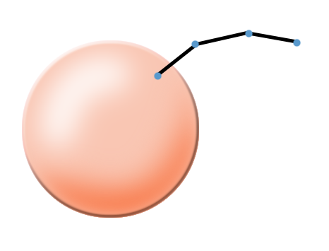
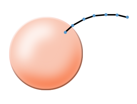
- Spline Type - Changes the spline calculation method for all splines (you can toggle between them).
‘Interpolating’ splines pass through each knot of the guide, whereas ‘Approximating’ splines act more like Bezier splines. ‘Interpolating’ splines can be bent tighter, ‘Approximating’ splines are smoother.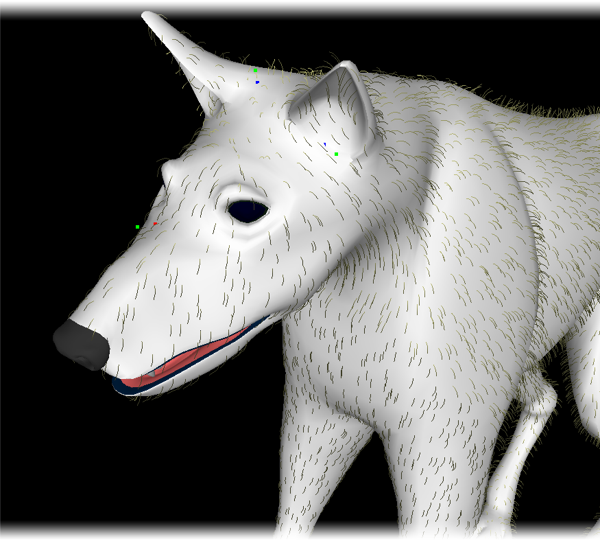
Left: ‘Interpolating’ Splines; Right: ‘Approximating’ Splines
Add Guide
To place a guide on your model to control the fibers, click this button (or press the hotkey ‘g’) then select a polygon on your model that will serve as the placeholder for your guide. You can only place one guide per polygon.
To add many guides in one go, use the ‘Grow’ button to add fibers to your model and set the ‘Fiber Qty’ setting to the number of guides you require. Then click the ‘Okay’ button to commit your settings. Run the Strand Modeler again and use the ‘Add Guides’ popup menu selecting the layer that contains the fibers you just created. These will then load up as guides and not fibers. Or you can select ‘Current Fibers’ option which is a much quicker way of doing the same operation.
- Scale (Guides) - Scales the length of the selected guides, this will also scale the length of any fibers they are controlling as a result.
- Del Guide (Delete Guide) - To delete a guide hold down the Shift key and drag a box selection using your mouse over the guide you wish to delete (normal left mouse clicking doesn’t select a guide as this is how you move guide knots, not select them). You can continue to use this same method to select multiple guides. When a guide is selected the last knot will be highlighted white. You can now click the ‘Del Guide’ button to remove the selected guides.
- Add Node (Guide Knot) - To add a new node (or knot) click this button, It will add a node / knot to ALL guides. Currently, all guides must have a uniform node / knot count.
- Del Node (Guide Knot) - Clicking this button will delete the last node or knot from ALL guides.
- Add Guides (Load Guides) - You can add or load guides in a number of ways using this popup menu. You can load guides previously saved on layers in your object. 2-point polygon fiber chains can also be loaded back in as guides, and not fibers.
Guides can be created from fibers currently growing on the surface. Note: guides created using this method take on the exact shape of your current fibers, so any styling done to them will be reflected in the shape of the guides.
You can also create guides based every polygon on the currently selected surface - guides will be created matching each polygons ‘normal’ vector. Or you can create guides based on every single point on the currently selected surface; again these will be created using the point normal vector.
Save Guides
Saves the current guide set to the next available layer in Modeler.
Select Node (Knot)
This popup allows you to select either the First / Last node or knot on every guide (it selects all knots on every guide because any deletion of knots must be equal on all guides). You can also use Previous / Next to step through intermediate knots, or use the ‘None’ option to deselect.
Clear Guides
Clear all guides on the surface.
IK Guides
By default, when manipulating guides using the mouse, they use an IK (Inverse Kinematic) method of handling the guide chains which keeps all knots at an equal distance apart. If you wish to override this method, uncheck the ‘IK’ option. You will now be able to move knots anywhere you desire.
Interpolation
Guides have several ‘Interpolation’ methods available to them to further refine their area of influence on the fibers. Clicking the root knot on a guide changes its interpolation method (the color also changes to show which mode you’re in) and if applicable the radius of influence the interpolation has.
Left: Sharp Wide; Right: Interpolate Wide
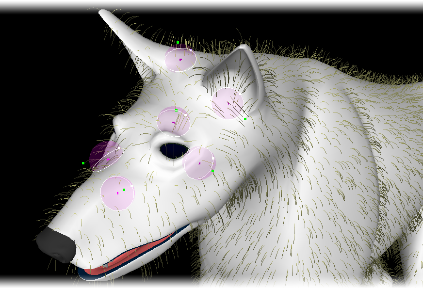
Left: Radius Sharp; Right: Radius Sharp w/fx

Left: Radius Interpolated; Right: Radius Interpolated w/fx
Bundled
- Radius - Sets the radius of influence for interpolation modes that support it.
- Bundle % - The bundle percentage pulls all fibers in the radius of influence together forming a ponytail.
- Bundle Bias - Sets how far along the fiber's length they start to bundle together. At 0% the bundling starts nearer the tip of the fibers, at 100% bundling starts nearer the root.
Random Tab
This tab contains controls for randomizing the appearance of the fibers to create a shaggier look.
- Length - Randomizes the lengths of the fibers.
- Jitter X - Randomizes the X axis direction the fiber as it leaves the object's surface.
- Jitter Y - Randomizes the Y axis direction the fiber as it leaves the object's surface.
- Jitter Z - Randomizes the Z axis direction the fiber as it leaves the object's surface.
Gravity Tab
Contains controls for simulating gravity affecting the fibers to create a more natural appearance.
- Strength - The percentage of gravity affecting the fibers. Gravity bends the fibers in the direction of the arrow in the gravity direction control box.
- Use Normals - Percentage of force pulling fibers into the direction of the surface normal. Useful for the creation of surface-hugging fibers instead of being pulled only in the direction of gravity.
- Gravity Direction - The gadget allows you to change the direction you want the gravity force to be directed. To modify the click and drag the arrow using the mouse.
- Reset - Reset the gravity direction arrow to point down.
- Slope - Changes the force of the gravity effect according to the slope of the surface. Fibers on upward and horizontal facing surfaces receive more of the gravity strength, whereas fibers on downward and vertical surfaces receive less of the gravity force.
Tools1 Tab
Tools for fiber styling can be found on this tab.
- Curl % - Percentage of curl. Use in combination with curl turns to create various curl types. These require many edges for the smoothest effect.
- Curl Turns - The quantity of curl revolutions. Set to 1 a curl would make a single 360 degree curl.
- Randomize Curling - Randomize the phase of the curl start.
- Kink - Sets the percentage of back and forth kinking like pleats or accordion fold.
- Slope Shorten - Shorten the fibers according to the slope of the surface. At 100% the fibers facing down are scaled to 0 and fibers in between are scaled accordingly.
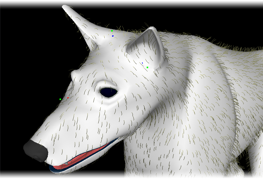
- UV Bias - Set the directional bias to be applied over each polygon laying down according to the direction chosen. Think of this like a joystick at the North Pole. Setting UV Bias to have a specified direction lays all the fibers over into this direction. Handy for the creation of parts and the whorl at the top of the head.
Bias works by laying a fiber up or down against its underlying polygon. It can be used to create sleek lay-down types of hair. To illustrate, say you are doing a Wolfman. In the normal UV position, the hair part would be at the top of the head when contoured. All the hair would be flowing down over the face. If you changed the UV contouring setting appropriately, the same operation would produce the part at the nose. Then the hair will flow from the nose back across the face, more like animal fur.
- Reset - Reset the UV bias and directional bias back to default.
- Dir Bias - Use this to tip the “UV bias joystick” at the North Pole into a different orientation.
Tools2 Tab
Tools for fiber styling can be found on this tab.
- Clip Object - Select another modeler layer as a clipper object to cut the hair that intersects it. The clipper object is shown in wireframe. For instance, you can use a box in another layer to clip hair into a flat top style. Imagine hair growing into a form and stopping where it intersects.
- Clip Transformation - The clip object can be moved by selecting the transform and using the Ctrl key to manipulate it.
- Reset - Resets the clip object back to the origin.
- Hide - Hides the clip object.
- Collision - Set the fiber collision with the surface. These are subject to effects and be aware that guides plus effects can drive fibers into the surface since by nature those are predetermined and subject to interpolation.
Guide knots themselves are subject to collisions and can be placed down on a surface. - Axis Mirror - Only available when using guides and is handy for creating a symmetrical hair part. Place the guides on one side and fibers on the other side to use them in a mirrored fashion.
- Length VMap - Choose an existing weight map to alter the length according to the weight map values from 0 to 1.
- Density VMap - Choose an existing weight map to alter the local fiber density according to the weight map values from 0 to 1.
- Make UVs - UV coordinates are created for the fibers, 0 at the base and 1 at the tip. Useful for weighting animated fibers using clothFX.
Options Tab
Contains preferences for the FiberFX Strand Modeler.
- Fiber Color - Sets the color of the fibers within the Interface. This does not affect the fiber's color when rendered.
- Bkg Color (Background) - Sets the color of the viewport background within the Interface.
- Grid - Draws an X-Z grid in the viewport.
- Reset Current Surface - Reset current surface to default settings, any styling will be lost. Guides will not be deleted.
- Surface Offset - Push points off the polygon by set amount. Useful to offset single point polygons from the surface.
- Knots Only - Show only the guide knots, turning off the spline drawing.
- Ends Only - Show only the root and tip knots, hiding any knots in-between.
- Fat Lines - Thickens up the fibers and guides within the interface to make them more visible.
Strand Tool
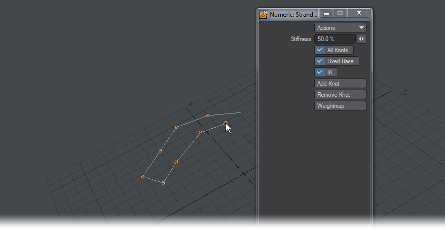
This is an interactive Modeler tool for adjusting fiber strands using IK after creating them in Strand Modeler. When launched the Strand Tool scans the selected layer and builds a list of fiber strands. A handle is drawn at the end of each strand and inverse kinematics is used to calculate the new position when moved.
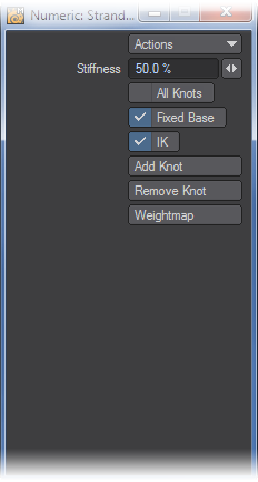
Pressing the N key brings up the numeric panel allowing you to set the IK strength. The numeric panel also lets you toggle all knots to adjust interior knots in a strand.
The LMB is used for dragging your control points around and the RMB for scaling the distance between control points.
- All knots - Show handles for all knots for dragging. When off only the end handle on a chain will be shown.
- Fixed base - When off, the chain's base knot is not selectable for editing.
- IK - Switch for inverse kinematic chain edit handling. With this on, chains will move in a sinuous fashion, with it off only the control point you are moving will be displaced.
- Add knot - Add knot to end of chains.
- Remove Knot - Removes the last knot on chains.
- Weightmap - Create weightmap containing 0<>1 values, prompts for a name.
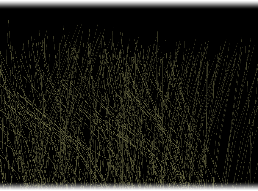
Strand Maker
This Modeler tool allows you to create fiber strands using standard LightWave Modeler tools. When you run Strand Maker, it scans the polygons in the current layer then moves to a new layer and builds fiber strands based on the geometry.
You can also use LightWave Modeler's curve drawing tools like ‘Sketch’ and ‘Spline Draw’ to create fiber strands by hand or convert whole objects into fibers. Any objects with edge loops will create fibers that are continuous, whereas open-ended curves will create strands exactly matching them.
Once these strands have been creating, you can use them back inside the Strand Modeler as fiber guides for further controlling your fibers.
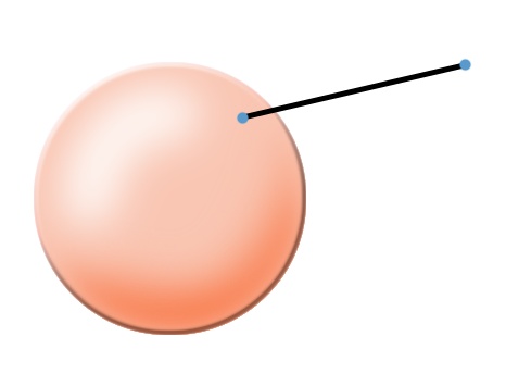
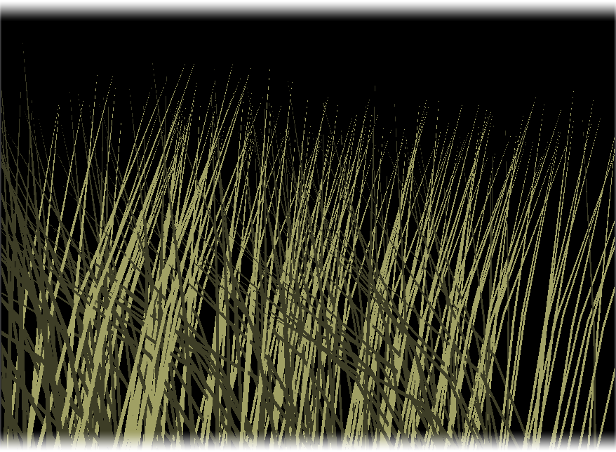
In the quick example below, creating a ball object, delete half to create a hemisphere. Flattening it in the Y-Axis and finally converting the geometry to fibers using Strand Maker could be the beginnings of a spider's web.
Converting Existing Geometry to Fiber Strands Using the Strand Maker
This tool has no interface and is a one-click way to create two-point poly chains from polygons for use with FiberFX. Since FiberFX now works with curves directly, this tool is less needed.