Texture Guide
This command allows you to interactively create a UV Map for selected polygons.
How do I use this tool?
To use this tool, make sure that one of your viewports is set to UV Texture, and select the polygons you would like to map. (If there are no selected polys, this tool will map all visible polygons.) If you would like to see the texture on your object while you make the UVs, you will need to assign an existing UV Map to that surface in the Surface Editor.
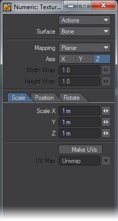
Click the command, and open the Numeric Panel, if it’s not already open. Click on the Actions button, and choose Activate from the drop down menu. The rest of the panel will light up, and the selected polys will be visible in the UV Texture viewport, if you are working with an existing map.
Click Make UVs at the bottom of the Numeric Panel, and either type a new name into the UV Map field to create a new map, or choose an existing map from the drop down menu. The list contains all the names of all the UV Maps used during the current session, whether or not the objects remain open, and whether or not the maps have any points assigned to them.
When you do, that map will become the active map in the VMap Bar at the bottom of the screen, and you’ll be able to see the UVs for the selected polys in the UV Texture window. The fun is about to start!
Choose the Surface you would like to make the UVs for. All the visible surfaces in the object will be listed.
Then choose your Mapping method. There are five to choose from.
Planar
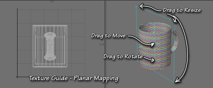
Planar is very similar to the Planar Mapping method you may already be familiar with. It projects the UVs onto the UV Map using a flat plane. When you choose it, you’ll see that plane represented as a orange rectangle in the viewports. You can choose the axis using the X, Y, Z buttons below the Mapping field. As you do, you will be able to see the results of the various orientations in the UV Texture viewport.
You can scale the map interactively by dragging the corners of the orange mapping rectangle, or by using the spinners or typing numbers into the fields in the Scale Tab. As you do, you will notice that, the larger the mapping rectangle, the smaller the map, and vice versa. This is because the object is occupying a smaller (or larger) percentage of the mapping rectangle. If you hold down the Ctrl key before you begin to drag, the scaling will be constrained to the last drag direction.
You can change the position of the plane by dragging the center cross, or by using the spinners or typing numbers into the fields in the Position Tab. Holding the Ctrl key will constrain the dragging to vertical only. Notice as you drag that when you drag right, the mapped object moves left in the UV Texture viewport, and vice versa. This is because it’s occupying the left (or right) side of the mapping rectangle.
You can rotate the mapping rectangle in the direction perpendicular to the rectangle by clicking and dragging on the dotted orange handles that extend from the center square. However, you can only interactively rotate on the axis perpendicular to the rectangle. If you want to rotate it in all three directions, you will have to use the numbers or spinners on the Rotate Tab. The tab uses Heading, Pitch, and Bank; controls that you should be familiar with from Layout.
Heading, of course, controls movement around the Y axis, Pitch around the X axis, and Bank around the Z axis. So, if you have chosen the Z axis for mapping, you can drag to change the Bank, but Heading and Pitch can only be changed in the Numeric Panel.
Notice, once again, that the object appears to move in the opposite direction to your movement when you drag, because you are changing the corner of the mapping rectangle that it occupies.
Cylinder
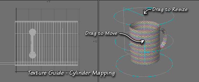
Cylinder is the same as the Cylindrical Mapping mode you have seen in other places. It projects the vertices onto a cylinder, and then unwraps that flat onto the UV Map. The cylinder is visible as a simple orange wireframe cylinder in your viewports.
Choose the axis you would like to use as the length of the cylinder by clicking on the appropriate button (X, Y, or Z.) You can also choose the Width Wrap, which determines how far the polys will spread in the U direction on the map. You can adjust it to keep the polys proportional as you change the scale of the cylinder.
You can change the height of the cylinder by dragging on the top or bottom line. To change the other two directions, you must use the spinners or type the numbers into the fields in Scale Tab of the Numeric Panel. Once again, the larger the cylinder, the less space the polys take, and the smaller they appear on the map.
You can change the position of the cylinder by dragging the central orange cross. If you want to be more exact, you can use the fields in the Position Tab of the Numeric Panel.
Finally, you can rotate the cylinder; but only by using the fields in the Rotate Tab.
It’s interesting to note that each mapping method inherits the Scale, Position, and Rotation that are already present. So, if you wish to interactively rotate the cylinder, simply start with Planar Mapping, rotate the rectangle, and then switch. If you chose the correct directions, your rotation will be in place.
Spherical Mapping
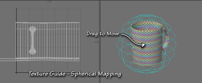
Spherical Mapping, once again like Spherical Mapping in other parts of LightWave, projects all the points onto a sphere, and then unwraps it onto the flat surface of the map. The sphere is represented by a orange wireframe sphere in your viewports.
As always, choose the axis you wish to use as the poles of the sphere. You can also adjust both the Width Wrap and the Height Wrap, spreading the polys out in the U or V direction, to obtain the desired result.
You cannot interactively change the Scale or Rotation of the sphere; you have to do all of that using the tabs in the Numeric Panel. You can, however, change the position by dragging the center blue cross, and you can watch the UVs update in real time as you do so.
The regular caveats about size and direction which seem to be backwards apply again, of course, as does the note about the persistence of previous adjustments, as long as you haven’t closed the tool.
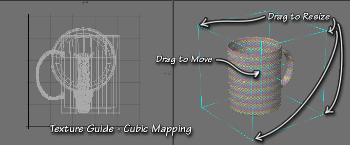
Cubic Mapping
Cubic Mapping corresponds to the Cubic Mapping you may know from the Surface Editor. The projection space is represented by a orange cube in your viewports.
You can scale the cube interactively by dragging on any of the corner handles, or you can use the spinners or type numbers into the fields in the Scale Tab for greater accuracy. You can position it by dragging the center orange square, as always, or by using the Position Tab. To rotate, though, you have to use the Rotate Tab, and type or spin. The usual caveats apply here, too.
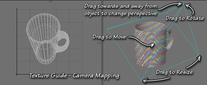
Camera Mapping
Camera Mapping is an extremely flexible planar map that uses perspective. It’s represented by an orange pyramid in the viewports. You can think of the flat, rectangular part of the pyramid as the picture that will be used for the map, and the point as the camera lens.
You can scale the rectangle by dragging on its corners, or by using the Scale Tab of the Numeric Panel. You can change the position by dragging the center orange across in any viewport, or by using the Position Tab. You can change the rotation by dragging the point of the pyramid in any viewport or by using the Rotate Tab.
You can change the perspective amount by moving the point towards or away from the object. This changes the Camera field of View. As is normal with cameras, the wider the field of view, the more perspective you have. (You can do a kind of fisheye UV Map, if you are so inclined.) The narrower the FOV, the less perspective.
All the usual caveats apply here, as well.
As you do all of this, no matter which Mapping type you are using, you may find that the UVs have moved out of the UV space. It’s not at all uncommon for them to do so. If you can’t find them, zoom out. (and if all else fails, close and reopen it, they will show up again)
When you are pleased with your results, tap the Return key or the Spacebar to drop the tool and make the UVs.
You will notice that there are no points in them anywhere; which means that you can’t perform any direct manipulations on them. They might be exactly what you want, in which case, you’re finished.But, if you would like to do more, it’s easy to turn this map into a normal one, with points. Just use the Unweld command (Detail > Points > Unweld). This will put points on all the polys, allowing you to use all the Modify tools, as you normally would. If your models are simple enough, you can Unweld selected points; if not, you can effectively Unweld the entire model. Just be sure not to move anything in X,Y,Z space, and the Merge command (M) will put it all back together again when you’re finished mapping.