UV
What are UV Maps?
Sometimes, when mapping textures onto objects, you will find that the normal projection mapping just doesn’t work. This usually happens when the object is organic, or irregular in shape. For those occasions, there’s UV Mapping.
UV Mapping adds two extra coordinates to the points in your object; those on the U and V axis, running horizontally and vertically through a flat plane on which you can paint your texture. Since the coordinates are assigned to points, it’s essentially as if that painted texture was fixed to the surface of the object, with pins where all the points are. No matter how irregular your object is, or how it moves or flexes, those pins stay in place, and the texture stays right where you put it.
Technically, it’s not as accurate as projection mapping, because the texture is really only exact at those points, and merely interpolated everywhere else, but artistically, it works.
The trick is to make the map first. LightWave has the tools for that.
UV Texture Maps
Sometimes, standard image mapping tools (i.e., planar, cylindrical, and spherical mapping) may be somewhat limiting where the surface is irregular in shape. These techniques usually work well only where you can globally map the entire texture image using a linear interpolation along two axes. The object geometry essentially has no influence on how the texture is applied.
However, what if you could assign areas of a texture image to points on the surface, essentially tacking it down at key points? Well, you can with UV mapping in Modeler. Between the tacks, the image is stretched smoothly.The U and V refer to texture map coordinates and are really not much different than the XYZ coordinates you are familiar with. In fact, UV mapping is the process of setting up a relationship between the two dimensions of an image, U and V, with the three dimensions of an object surface, XYZ.
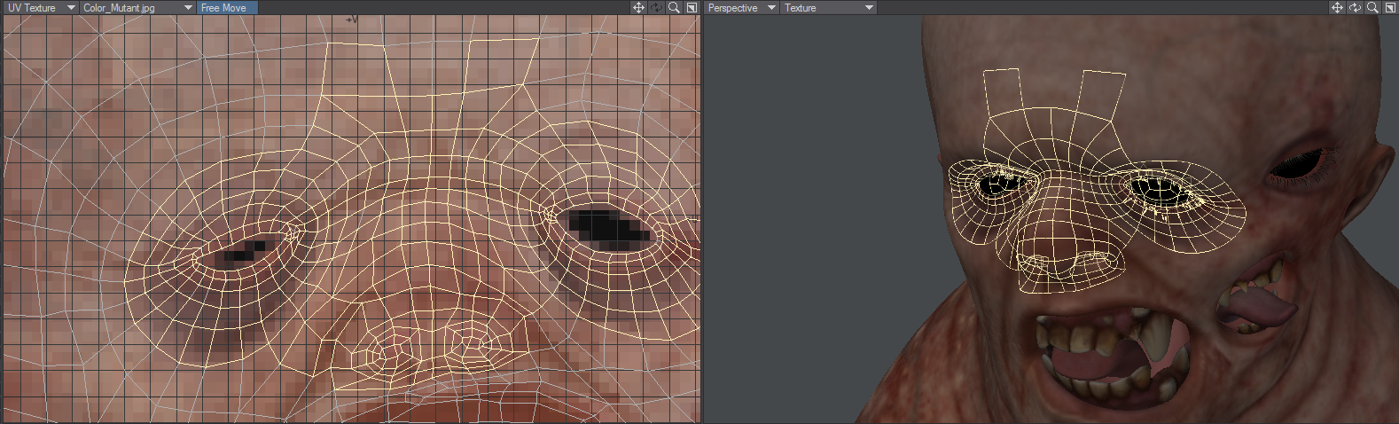
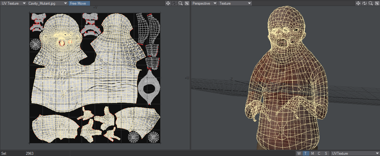
UV Map on the LightWave 10 Creature Kit Mutant character by Luis Santos. Note the selected polygons in both views.
Once this relationship is set up, changing any parameter (i.e., U, V, X, Y, or Z) will also relatively change the appearance of the texture mapping. With UV mapping, the object provides additional information for texture mapping, which can be different for any given point on the surface. The texture is more or less stuck to points on the surface using a relationship that you define.
UVs and Projection
UVs have to come from somewhere. For existing polygonal models, the choices are limited to setting the UV coordinates for each point in the object manually, or applying some projection, which automatically generates the 2D texture coordinates from the given 3D point positions. In LightWave, you can create UVs by using projections, which also happen to be the same as the standard projections for texture mapping (i.e., planar, cylindrical, and spherical).
Usually, the projection for the UV map is not perfect for the model everywhere. The projected UV map must be tweaked - eyes and nostrils moved over the right parts of a face, or texture features matched to geometry features.
Keep in mind that standard projection mapping is more accurate because it has some exact, continuous value over the entire surface. UV mapping, on the other hand, is technically accurate only at small sample points. The surface is interpolated for the large areas in between the sample points. Adjusting the sample points so that the interpolated areas look right is more exacting and the reason why UVs are thought to be more difficult to use.
For illustration purposes, let’s say you had your texture image printed on a piece of very flexible rubber and wanted to fit it on a toy car made of wood. You could conform the rubber material to contours of the car by tacking it down with thumbtacks. That is more or less what UV mapping does. However, it is a little bit reversed: what you do is tack the UV points down onto the image.
Discontinuous UVs
VMaps support discontinuous values across polygon boundaries, which are useful for UV texture coordinates, gradient weights, and other VMap-controlled surfacing parameters.
Discontinuous UVs are automatically used when appropriate with Modeler’s modeling tools.
Unweld Command
The Unweld command (Detail > Points > Unweld) creates multiple copies of the selected points so that none are shared by two polygons. Each polygon is given its own copy of the selected vertices, and VMap values for the polygon are made continuous over the new vertices. This tool is the key to being able to edit discontinuous UVs.
Merge and Weld Commands
When points are merged with the Merge Points (Construct > Reduce > MergePoints) or Weld Points (Detail > Points > Weld) command, any introduced discrepancies between VMap values are resolved with discontinuous UVs.
Merge points will no longer merge points that are at different locations in any of their morphs. This prevents distortions of the topology or discontinuities in the morph VMaps. It also provides a method to force seams in the mesh.
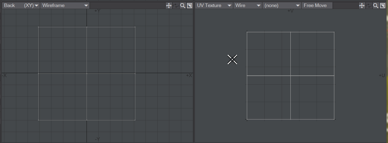
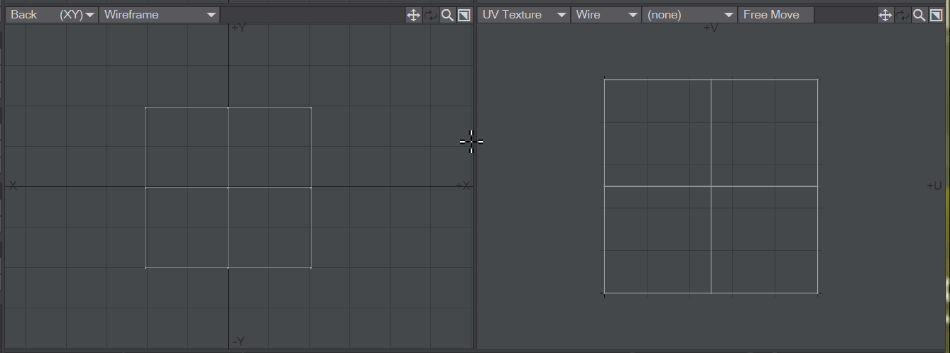
Free Move
When in UV Texture mode in the viewports and Free Move is active, selected polygons will separate into a new island when modified.


Free Move on and off
 Display Styles
New to 2019 are the following UV viewport display styles that compare the polygon size of the object's geometry and adds them all together for the total area, plus each individual polygon, then does the same for the polygons in the uv map to have two values for each:
- Wire - The default display mode is the way the UV window has been displayed since it was available
- Stretch - Shows the difference in edge lengths for the totals. Blue means the edge lengths are shorter in the UV map compared to the geometry, Orange means the edges in the UV map are longer than the source geometry. Edges that are dark blue are the same length
- Scale - Shows the difference in polygon area between the UV map and the geometry. If the polygon is smaller in the UV map, then it is colored orange. If the polygon in the UV map is larger than the source geometry it is colored blue. Polygons that are sized similarly in the UV map compared to the geometry are transparent.
- Angle - The whiter the polygon in the UV window, the greater the difference between the angle the UV is showing compared to the geometry angle. The ideal for an optimum UV is to move its representation in the UV viewport to be transparent.
- Overlap - When polygons in the UV map overlap, they are highlighted in the UV window with red.
The calculations needed to show these different states of UV maps are quite expensive, so it's good to go back to the standard Wire to preserve Modeler stability when you are done
UVs Outside the Box
You may have noticed that UV coordinates can appear outside of the UV box. That is, have U or V values less than 0 or greater than 1. The texture is essentially tiled, so these points are still attached to some part of the texture. It is sort of like the old Asteroids video game where the ship moves off the edge, but appears on the opposite side.
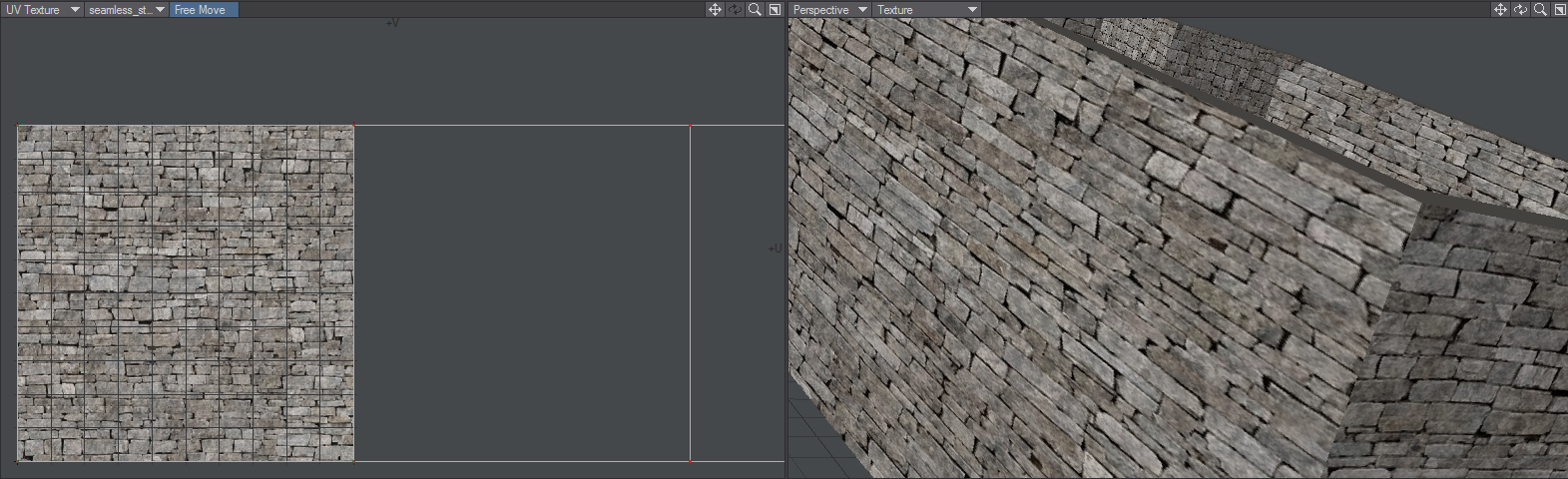
The image shows a wall made in LWCAD with a UV map that only encompasses one polygon of the wall. The other polygons in the UV map are outside the 0,1 square and so repeat what is inside it.
It may help you understand the result by thinking of two rotation keys in Layout of, say, 0 and 720 degrees. From the viewer’s perspective, the orientations at those keyframes are the same; however, there is a (motion) path between the keys that LightWave interpolates. For UVs, there is a texture path. LightWave interpolates the texture between the UV coordinates.
Let’s say you had U coordinates at .9 and 1.3. Now although 1.3 and .3 would be at the exact same position on the texture, there would be a big difference in the interpolation path of .9 to 1.3 and .9 to .3. The latter would be backwards.
UDIM
UDIM is a way of assigning multiple images to a single UV map, using a number to indicate blocks of UV space separated into ten columns of U before V increments. This makes parsing an image list used for texturing simple given that the images will have numbered filenames (1001, 1002, 1003... 1011, 1012, 1012...). It also simplifies the Image Editor with a single UDIM image in the list of images, rather than several numbered images. UDIM's major benefit is that it allows texture maps to be as detailed as necessary, with image maps at different resolutions for different areas of the object. As an example, in days gone by and with only one UV map, the map would need to be high resolution to get all the detail for important areas while less important ones got too much dedicated space. With UDIM, you can use high-resolution tiles for important details like facial features but consign things like the soles of feet to share a tile with other elements of lesser importance.

In this example screenshot with a model exported from MakeHuman, we see the head and mouth get a UDIM tile, followed by the body and eye sockets. Next, the right and left hands, followed by the feet on a single tile. It's probably overkill, but each eye has its own tile, finishing up with both pupils on a single tile.
UDIM Workflow