UV Interpolation
Usually Subpatch interpolation behaves differently on the outer edge of a mesh than inside a mesh. Since discontinuous edges are outer edges relative to a UV map or UV map island, but are inside edges relative to the mesh, it is not always possible for LightWave to automatically perform a correct Subpatch interpolation over discontinuous edges or over edges that are shared by multiple UV maps. For these types of situations, the following interpolation types have been offered to get the least distortion out of a UV map.
Interpolation Type
Linear - The UV map is interpolated linearly, most similar to the original mapping option and does not use any subpatching at all.
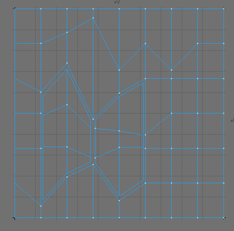
A UV map with two UV islands enclosed by a 3rd large UV island. Linear Interpolation Mode
- The edges on the very left and right of this UV map are discontinuous, as are the edges along the two small islands in the centre. In this case the biggest problem is that some vertices are shared by all three UV islands. This makes many of the interpolation- methods fail. The situation would be even more severe, if each UV island was in its own UV map.
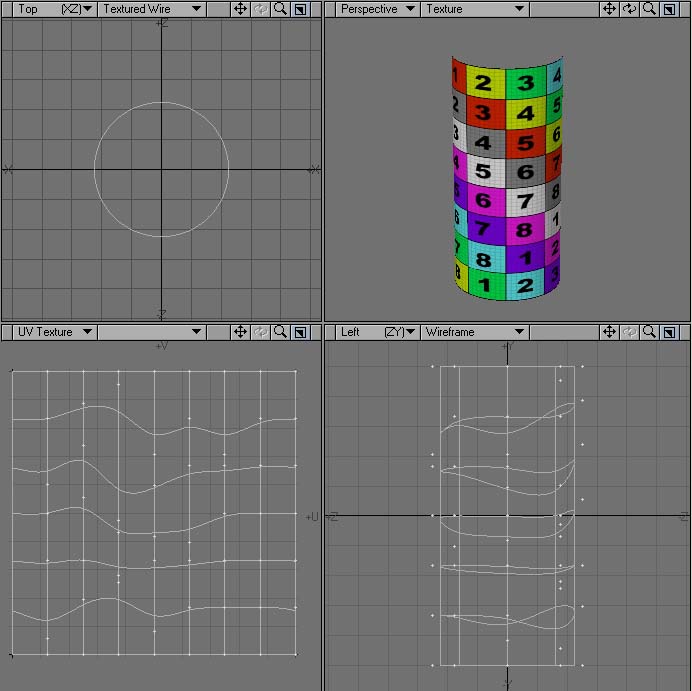
- Subpatch - All Edges are interpolated along the subpatch lines, as if the UV map was a subpatch mesh. (Note that the discontinuous edges do not line up.)
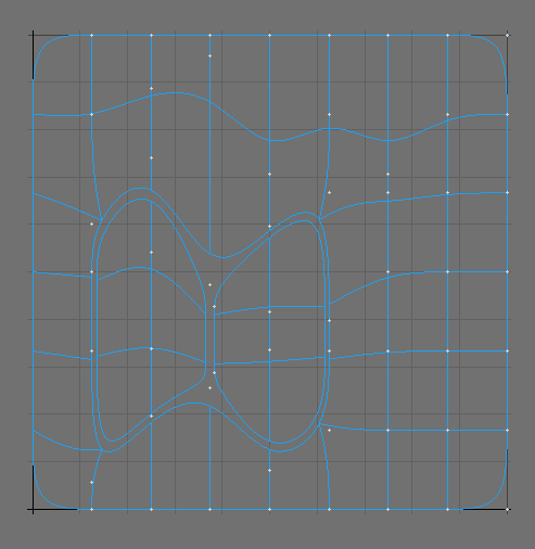
Subpatch Interpolation Mode
- Linear Corners - Corner-Points that are along the outer edge of the UV map, but not the edge of the mesh, are interpolated linearly. Notice that it looks better than subpatch, but the discontinuous edges still do not meet up.
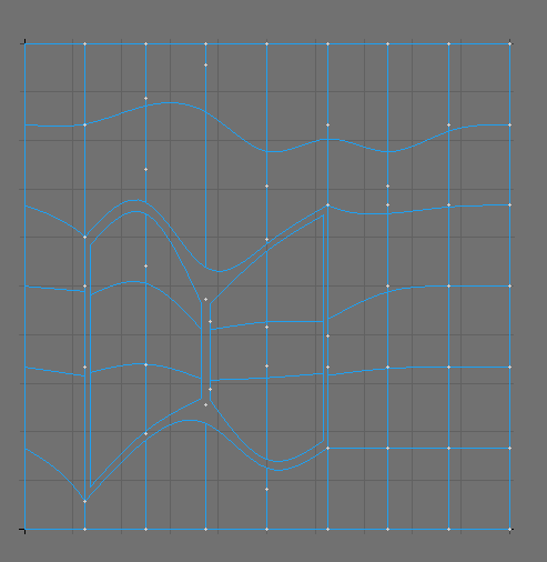
Linear Corners Interpolation Mode
- Linear Edge - Edges that are along the outer edge of the UV map, but not the edge of the mesh, are interpolated linearly. Discontinuous Edges now line up, but due to lack of cubic interpolation, some distortion may still occur.
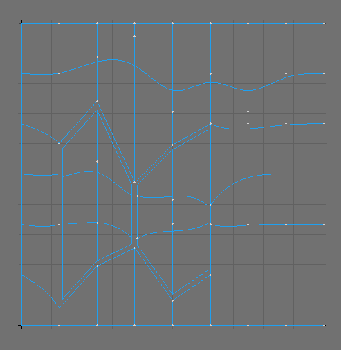
Linear Edges Interpolation Mode
In this special case only the “Linear Edges” method would allow for well aligned discontinuous UV edges. However you would have to allow for some distortion along these edges.
Across discontinuous edges: Interpolation occurs along discontinuous edges. This method usually provides less distortion along discontinuous edges. A discontinuous edge can be considered a point that shares two separate polygons on a mesh, yet falls on the edge of the UV map so the two polygons are on opposite edges of the UV map. This option lines up the points so the two edges meet up. Please note that this option does not work across multiple UV maps.
Across Discontinuous Edges Interpolation Mode
If heavy scaling is used or parts are rotated, Across Discontinuous Edges can produce errors. However, this solution is recommended first, since most of the time, the least distortion occurs at discontinuous edges.
The Subpatch Interpolations can be further edited in the Assign UV Coordinates window and the Vertex Maps Panel.
Axis
Choose the axis you wish to align your UVs to: X, Y or Z.
Settings
In addition to choosing the axes, you can also decide whether to leave the Center and Size settings on Automatic, or to adjust them Manually. If you click on Manual, the Center and Size fields will become active. For most purposes, it’s recommended to simply leave them on Automatic. Once you have a UV Map and are ready to paint it, don’t make a screenshot, which will be of poor quality at best, and will need to be manipulated before you can use it. Instead, go to File > Export >Export Encapsulated Postscript, choose Texture UV from the View field, and make an .eps file, so you can have clean, high-resolution maps.