UDIM Workflow
UDIM is a way of assigning multiple images to a UV map, using a single number to indicate blocks of UV space separated into 10 columns of U before V is incremented. This makes parsing an image list used for texturing simple given that the images will have numbered filenames. It also simplifies the Image Editor with a single UDIM image in the list of images, rather than masses of numbered images.
A UDIM workflow is vital in other applications such as Mari and Substance, but even purely in LightWave can be extremely beneficial for a number of reasons. The first is that surfacing in LightWave only allows one UV map per texture meaning that you need to divide areas into multiple surfaces if you wish to use different UV maps or fit everything into one giant map that has the limitation of being bigger than it needs be for unimportant details and yet always too small for those details that really matter. Furthermore, if you do use multiple surfaces for the different UV maps, there will always come an area you wish to cross between two UVs and thus two surfaces. UDIM is a cure for these problems.
As an example, here is a VPR screenshot of 18 objects, all planes for simplicity, each UV-mapped.

They are all textured using what seems to be a single image in the Image Editor, but is in fact 16 separate PNG files. If we go into Modeler, we can see how the planes are arranged.
In this GIF animation we show the UV space. Then we show plane_001 of our scene, which we can see fills the UV space. We show the UDIM image used and can see it extends far beyond the traditional UV space. Showing plane_008, then plane_000 shows where they sit on the UDIM image. Black tiles indicate missing images - either deliberately or because the image sequence has ended before the U reaches 10.
While this example is artificially simple to make it more comprehensible, the UDIM technique means that multiple images can be assigned space in UV coordinates for UV mapping to take place while simplifying the image count. This example also shows one UDIM array used with multiple objects, but it can also be used for a single object with multiple maps (many other 3D applications only allow one UV map per object).
Traditionally in LightWave when polygons fall outside the 0-1 UV space there is a repeat of the texture. When using a UDIM workflow this is no longer true. To regain the normal behavior it suffices to use a non-UDIM image.
Creating UDIM image sequences
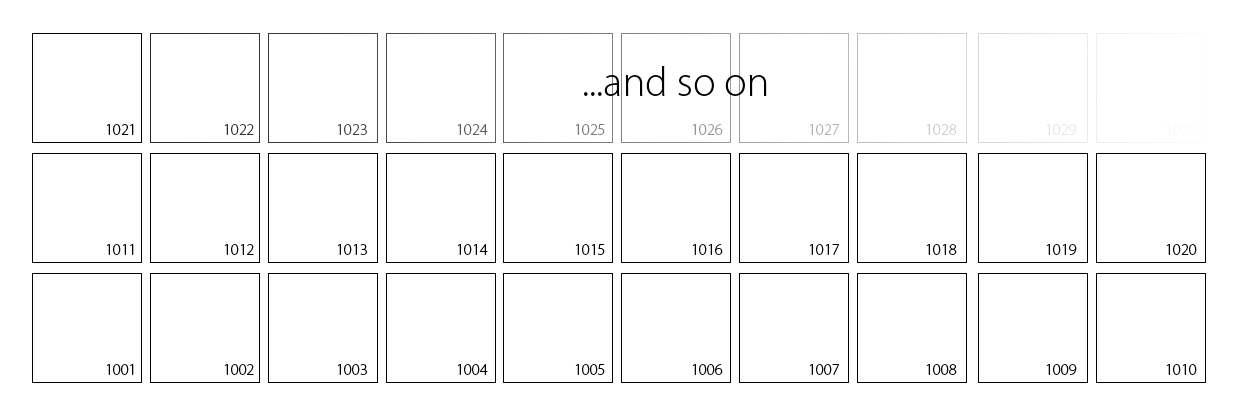
UDIM sequences are images with numbering starting at 1001 counting upwards. You should not start at a higher number. If you miss numbers (1004, 1006, 1007, etc.) there will be a black tile where the number would be. Tiles are created horizontally from left to right. Once the tenth tile has been placed a new row starts. The UDIM sequence name will be the filename before the numbers. If you use a separator (an underscore, period or hyphen for instance) it will be kept as part of the UDIM sequence name. The images in a UDIM sequence do not all have to be the same size, this means that some tiles can be very detailed while others have less.
Creating UDIM UV maps

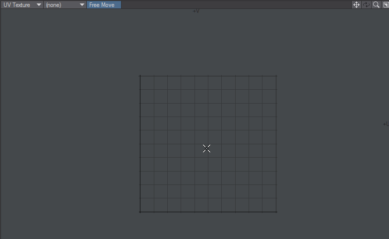
In order to create the tiles needed for a UDIM UV map, when you create the UVs for your object, keep to the same UV Texture Name and select the tile number from the field near the bottom of the requester. As stated above UDIM tiles are ten to a row, like so:
The padding field below ensures that you remain within a UV tile. UDIM maps are very sensitive to the boundaries of each tile so it is best to make sure you have some padding. 0.05 gives a five percent margin, which should be enough to ensure separation. If you aren't using UDIM, the padding can be ignored.