Filter List
Black & White
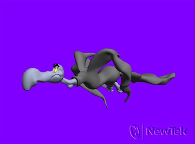
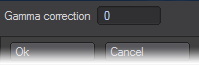
Creates a Black and White version of your render. Double clicking on the item in the list will bring up the Black and White panel where you can alter the gamma correction for the contrast levels.
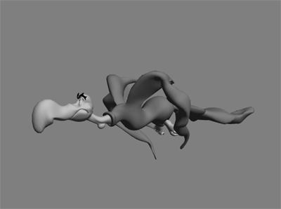
Left: Black and White Image Filter Applied, Right: Normal Render
Exposer
This filter normalizes high dynamic range (HDR) images for using as Image Maps and HDR output for displaying in applications that are not HDR-savvy. The intensity mapping is non-linear, similar to the light response process in the human eye.
This filter processes the HDR output created by radiosity and renders into better-looking, brighter pictures. It does this without impacting the accuracy of the lighting simulation, which can happen if you add ambient light or crank up lights unrealistically. It is really an essential part of the camera simulation, for a perfect digital camera. (The Virtual Darkroom filter is similar, but more complex. It simulates the two-stage process of film response to light, and print emulsion response to projection through the film negative.)
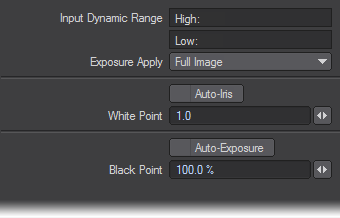
Although you can add this filter on the Image Editor, it is of limited use there and more useful as an Image filter on the Processing Tab of the Effects Panel. This is mainly because most images you load are not HDR images, so pre-processing is not necessary and normal gamma should probably be used, if necessary. Moreover, if you do load an HDR image, it’s probably because you want the extra data. (Using the HDR Exposure filter will eliminate some, if not all, of the extra data.)The Input Dynamic Range is an informational display showing the High and Low pixel-intensity values encountered in the last processed image. Note that when the panel first appears, this information is not yet known.
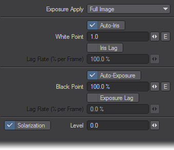
If you do not want the filter applied to the Full Image, set the Exposure Apply pop-up menu to Foreground to apply it only to scene items or Background to affect only the background (i.e., where your alpha would be black).
The White Point is the input intensity considered to be the hottest white. Anything above this will be the same white in the output. This control is overridden by the Auto-Iris option, which sets the white point based on the actual input image data. Adjusting the white point is similar to cranking down an iris on a film camera to limit how bright parts blow out in a photograph.
The Black Point, expressed as a percentage of the nominal black point (1/255), is the darkest non-black pixel level in the input image that will be preserved. Anything darker will come out black. The Auto-Exposure option overrides Black Point by using the actual image data to determine a black point in the incoming data. Lowering the black point is similar to increasing the exposure time for a photograph.
Once these values are set, the filter translates the incoming image intensity - in a process very similar to gamma correction - so that the darker colors get more of the output range than the brighter colors. In other words, the filter changes the spacing of intensity levels so more levels are devoted to low intensity, darker details.
Full Precision Blur
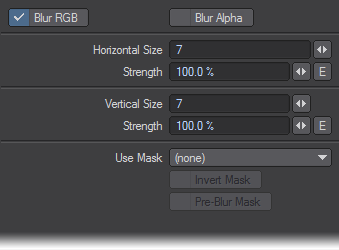
This filter will soften an image by blurring it. Change the Size values to increase the amount of blur horizontally or vertically. The Strength settings determine the amount of the effect. You can also choose whether to affect the RGB (color) and/or alpha data.
You can use the Rendered Alpha (channel) or a Special Buffer as a mask using the Use Mask pop-up menu. If you want the mask computed prior to the blurring, check the Pre-Blur Mask option, otherwise the mask accounts for any blurring. To reverse the mask, check Invert Mask.
The Special Buffer setting on the Advanced Tab of the Surface Editor can have a value from 0 to 1, with 0 meaning no blur and 1 meaning full blur.
Full Precision Gamma
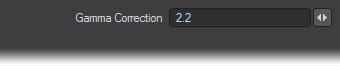
Display devices have a non-linear relationship between pixel values and physical light intensity - they do not excite the display phosphors linearly. This non-linearity must be compensated for to correctly reproduce intensity. The Gamma Correction value is the exponent value in the correction formula and determines how to convert pixel values to light intensity. The default, 2.2, is a common value used on images bound for video, but is not necessarily the optimum value.
Glow
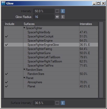
Glow will create a halo around surfaces based on their intensity. At the top of the panel there is a global intensity that can be enveloped and a Glow Radius setting that is also global. Intensities can be set and enveloped for individual surfaces in a scene and the result is multiplied over the final render. The alpha does not show the glow.
HDR Exposure
This filter normalizes high dynamic range (HDR) images for using as Image Maps and HDR output for displaying in applications that are not HDR-savvy. The intensity mapping is non-linear, similar to the light response process in the human eye.
This filter processes the HDR output created by radiosity renders into better-looking, brighter pictures. It does this without impacting the accuracy of the lighting simulation, which can happen if you add ambient light or crank up lights unrealistically. It is really an essential part of the camera simulation, for a perfect digital camera. (The Virtual Darkroom filter is similar, but more complex. It simulates the two-stage process of film response to light, and print emulsion response to projection through the film negative.)
Although you can add this filter on the Image Editor, it is of limited use there and more useful as an Image filter on the Processing Tab of the Effects Panel. This is mainly because most images you load are not HDR images, so pre-processing is not necessary and normal gamma should probably be used, if necessary. Moreover, if you do load an HDR image, it’s probably because you want the extra data. (Using the HDR Exposure filter will eliminate some, if not all, of the extra data.)
The Input Dynamic Range is an informational display showing the High and Low pixel-intensity values encountered in the last processed image. Note that when the panel first appears, this information is not yet known.
If you do not want the filter applied to the Full Image, set the Exposure Apply pop-up menu to Foreground to apply it only to scene items or Background to affect only the background (i.e., where your alpha would be black).
The White Point is the input intensity considered to be the hottest white. Anything above this will be the same white in the output. This control is overridden by the Auto-Iris option, which sets the white point based on the actual input image data. Adjusting the white point is similar to cranking down an iris on a film camera to limit how bright parts blow out in a photograph.
The Black Point, expressed as a percentage of the nominal black point (1/255), is the darkest non-black pixel level in the input image that will be preserved. Anything darker will come out black. The Auto-Exposure option overrides Black Point by using the actual image data to determine a black point in the incoming data. Lowering the black point is similar to increasing the exposure time for a photograph.
Once these values are set, the filter translates the incoming image intensity - in a process very similar to gamma correction - so that the darker colors get more of the output range than the brighter colors. In other words, the filter changes the spacing of intensity levels so more levels are devoted to low intensity, darker details.
Lscript and LScript/RT
Both allow you to run an LScript on a finished image.
Negative
Simply inverts the RGB values for the image.
Python
Applies a Python script to an image.
Python Black & White
Python version of the Black and White script.
Python Negative
Python version of the Negative script.
Sketch
Controls
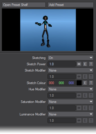
Open Preset Shelf & Add Preset: Sketch settings can be added to and taken from the presets shelf. When creating a preset, the thumbnail image is taken to be the preview image currently being shown (see below).
Preview
The preview image shows the effect of this Sketch plugin instance to the last image processed. The image will update as the Sketch settings are changed. Click on the preview image to force an update if needed.
Because the preview image is usually much smaller than the actual image, the preview is only an approximation of the effect.
Sketching
Sets whether sketching is enabled or disabled. This does not affect the hue, saturation, and luminosity modifiers.
- On - enable computation of sketch outlines
- Off - disables computation of sketch outlines. This effectively sets the sketch value to 0.
Sketch Power
Larger numbers makes the edges sharper. Typical values are between 0.5 and 3.
Sketch Modifier
Modifies the “sketch” value. 0 means no edge here, 1 means a very strong edge.
- None - leaves the value alone
- Scale - scales the value by the given factor
- Remap - arbitrarily change the sketch value, usually through an expression or texture
Sketch Color
The color to use for the sketch edges.
Hue Modifier
Changes the base colors of the image.
- None - does nothing to the hue values
- Rotate - moves the colors through the spectrum
- Scale - scales the colors towards the start/end of the spectrum
- Remap - arbitrarily change the hue values
Saturation Modifier
Changes the color saturation of the image.
- None - does nothing to the saturation values
- Steps - quantizes the saturation values in the given number of steps
- Scale - scales the saturation values
- Scale around mid - scales the saturation values around the mid point
- Remap - arbitrarily change the saturation values
Luminance Modifier
Changes the color intensities of the image.
- None - does nothing to the luminance values
- Steps - quantizes the luminance values in the given number of steps
- Scale - scales the luminance values
- Scale around mid - scales the luminance values around the mid point
- Remap - arbitrarily change the luminance values, usually through an expression or texture
Gradient Parameters
For textures used as Sketch settings, a number of custom gradient parameters are available:
- Sketch - the “sketch” value, between 0 (no edge here), and 1 (very strong edge here)
- SketchDir - the direction of the sketch edge
- Luminance - the luminance value at the current pixel
- Hue - the hue value at the current pixel
- Saturation - the saturation value at the current pixel
Sketch Channels
For envelopes and expressions used as Sketch settings, a number of custom channels are available in the Sketch group. Note that these channels are read-only (they are prefixed with an “r” as a reminder), and will only contain valid values during the evaluation of the Sketch plugin.
- rSketch - the “sketch” value
- rSketchDir - the sketch direction
- rLuminance - the luminance value at the current pixel
- rHue - the hue value at the current pixel
- rSaturation - the saturation value at the current pixel
SpriteEdger
The Sprite Edger image filter “unmixes” anti-aliased object edges from the background. It can remove background color fringing if the object is not rendered over black. It can also clip the alpha channel to form a 1-bit (0 or 1) mask. It can even use this mask to clip the RGB imaged edges, setting the pixels to the background color if they are outside the mask.
![]()
Textured Filter
Use Textured Filter to add the selected texture to the image before use. You could use this filter to add, say, an animated Fractal Noise pattern to a simple black image. Since textures are three-dimensional, particularly procedurals, use the Axis setting to use the X, Y, or Z of the texture.
The differences between the Axis selection can be subtle.

To see procedurals in viewports:
You can use Textured Filter to see procedural textures in your Layout viewport! Basically, you apply the procedural texture(s) to the image using Textured Filter and then map the image to the surface. Here’s how you do it:
- Load an image into the Image Editor. It really doesn’t matter what image you use since it will be obscured by the textures.
- On the Image Editor’s Processing Tab, add Textured Filter. Double-click it in the list window to access its options. Click the Texture button to access the Texture Editor.
- Change the default initial Layer Type to Gradient. This provides the underlying color. You can leave it white or change it.
- Add one or more procedural texture layers and set as you would normally.
- Load your object and open the Surface Editor.
- Click the Color attributes Texture button. Leave Layer Type set to Image Map on the Texture Editor that appears.
- Set Projection as you would normally and select your image from the Image pop-up menu. The procedural will now appear in your viewport.
This operation requires a lot of computations and Layout may seem sluggish as it computes the texture.
The image preview window on the Image Editor will show the texture as well. Thus, you can double-click the window to bring up the Image Viewer, from which you can save this compiled image. This can then be image mapped back onto the surface without all of the calculations required with Texture Filter.
If you use an image sequence instead of a still image, you can even see an animated texture! Note that if an animated texture is applied to a still image, it will not appear animated.
Video Legalize
The Video Legalize filter might be more appropriately named Hot Video, since it assumes that pure black, RGB 0, 0, 0, is mapped to the proper pedestal by the encoding device (e.g., 7.5 IRE for NTSC). The encoding device may not, however, correct hot pixels - that is, colors that exceed certain video specifications. This is where VideoLegalize steps in.
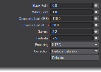
Pixel values are generally scaled into IRE units using the Black Point, White Point and Pedestal settings as follows: Level = Pedestal + (100 - Pedestal) * (pixel - Black) / (White - Black). White is always 100 IRE and PAL Black is 0 IRE. NTSC black is 7.5 IRE, thus for NTSC, the level would be computed: Level = 7.5 + 92.5 * (pixel - Black) / (White – Black).
Normally, an RGB level of 0.0 is black and 1.0 is white. If those are used for the Black Point and White Point settings, the NTSC level will be 7.5 + 92.5 * (pixel - 0.0) / (1.0 - 0.0) or just 7.5 + 92.5 * pixel. When the pixel is 1.0, the level is 100 IRE, and when the pixel is 0.0, the NTSC level is 7.5 IRE.
The actual computation is more complex than the above since other operations, like gamma correction, can happen.
The settings default to NTSC encoding, but you may also select PAL from the Encoding pop-up menu. (Note that you also need to click the Default button after selecting a new Encoding item.) You may change the individual settings from their defaults, if desired.
The Correct pop-up menu determines how the image is corrected to fall within the specified limits.
It is highly recommended that you use Video Legalize (as a post-process image filter) if you plan to use your images for video.
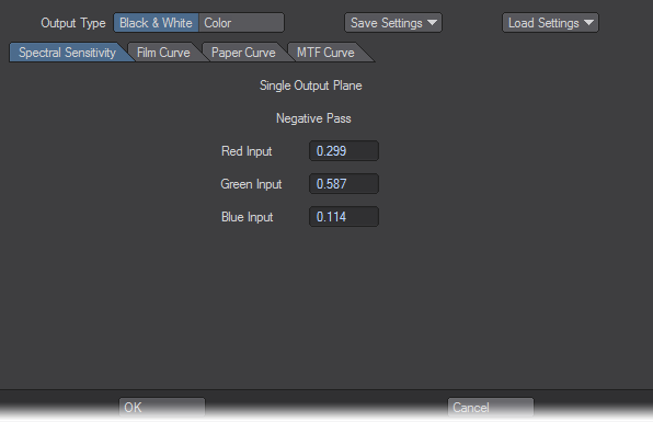
Virtual Darkroom
The Virtual Darkroom filter simulates the photographic capture of images. It is based on A Model for Simulating the Photographic Development Process on Digital Images, by Joe Geigel and F. Kenton Musgrave in the SIGGRAPH ’97 conference proceedings.
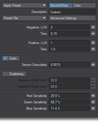
Global settings are the four controls located at the top. Output Type specifies whether the output image is Black and White (single-plane greyscale) or Color (three-plane RGB).
Basic Settings
Basic Settings control everything except for those settings on other tabs. Negative LUX is the illumination value for the negative pass - analogous to scene capture with a camera - which will affect overall brightness. Negative Time is the exposure time for negative pass, essentially the Exposure setting on the virtual camera. Positive LUX is the illumination value for the positive (printing) pass. Think of this as the brightness of the bulb in the enlarger or printing mechanism. Positive Time is the exposure time during the printing pass of virtual enlarger.Enable Scattering will activate the internal scattering effect. Negative Width and Negative Height are the width and height, respectively, in millimeters, of the virtual negative. These values are used in scattering and grain calculations. Enable Grain will activate the grain effect. Selwyn Granularity controls the intensity of the grain. Increasing this value increases grain, decreasing it will decrease grain.
Advanced Settings: Spectral Sensitivity Tab
If Output Type is set to Color, there will be six sets of RGB percentage controls. Each RGB trio specifies the percentage of the black and white output plane that is contributed by the input image plane named in the control. For example, the RGB trio in the upper-middle defines how the output from the negative passes on the spectral sensitivity module creates the green plane.If Output Type is set to Black & White, you specify what percentage of the red, green, and blue planes of the input image are used when they are combined into a single black and white image. This transition takes place in the negative (first) pass. During the printing (second) pass, there is only a single input plane, so spectral sensitivity is not used.
Film, Paper, and MTF Curve Tabs
You can enter up to 21 pairs that define the characteristic curve of the film and paper, and the function for modulation transfer used for scattering calculations. For each pair, the first value represents log (exposure) and the second value represents the density.
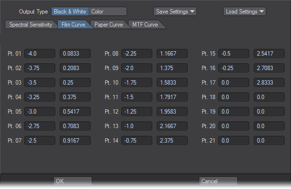
For all Curve tab entries, points should be entered in order starting with Pt. 01. If Output Type is set to Color, curves must be set for each output plane by selecting the appropriate Red Plane, Green Plane, or Blue Plane sub-tab.
VR Camera Export

This Image Filter will take stereo renders (from any camera) and bundle them correctly for use in compositing applications or websites for a stereoscopic workflow. Its settings are as follows:
- Destination - A choice of:
- Image Viewer - Sends the left eye and right eye images to the LightWave Image Viewer along with an image composited in the fashion you choose in Stereo Type.
- Image Files - Saves the left eye and right eye images in the format chosen, along with an image composited in the fashion you choose in Stereo Type.
- Image Type - The still image format you wish to use for the Image Files setting
- File Output - The directory for outputting composited stereo renders
- Stereo Type - Presents three choices:
- Left Over Right - the left eye and right eye renders are stacked vertically
- Left / Right - the renders are placed side-by-side
- Anaglyph - Creates a single image to be viewed with red-blue glasses
| Left over Right | Left / Right | Anaglyph |
|---|---|---|
 |  |  |
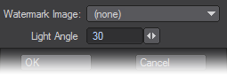
WaterMark
The WaterMark filter embosses an image in the lower-right quarter of your render. You can select any loaded image; however, grayscale images using a black background work best. The Light Angle field determines the direction of the implied light source.
 +
+  =
=