Tools
BlackBody Radiator
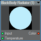
A Black body is an object that absorbs all energy falling on it. In LightWave, it can be used to give a color suitable for fire or explosions. The Color output is decided through a Kelvin temperature between 1000-25000, where 6500 is equivalent to daylight (and equivalent to 1).
Color Scalar
The Color Scalar node allows a color to be converted into a scalar. Double clicking the node will present a dropdown list of modes that determine how the conversion occurs. These are:
- Average - this outputs a scalar as the mean of the three color components.
Scalar = (Red + Green + Blue) / 3.0 - Maximum - outputs the scalar as the largest of the three color components.
Scalar = Max(Red, Green, Blue) - Minimum - outputs the scalar as the smallest of the three color components.
Scalar = Min(Red, Green, Blue) - Red Channel - outputs the scalar as the value of the red component.
Scalar = Red - Green Channel - outputs the scalar as the value of the green component.
Scalar = Green - Blue Channel - outputs the scalar as the value of the blue component.
Scalar = Blue - Luma - outputs the scalar as the luminance of the input color.
Scalar = CCIR 601 luminance values formula Y’ = 0.299 R’ + 0.587 G’ + 0.114 B’ so (Red x 0.299 ) + (Green x 0.587 ) + (Blue x 0.114 )
ColorTool
The Color Tool node takes the input color and provides a set of controls that allow it to be manipulated or processed and then output. The available manipulations are:
- Hue - allows the hue of the input color to be shifted by any number of degrees. The HSV color model specifies H as Hue being an angle with red at zero degrees, green at 120 degrees, blue at 240 degrees, and so on. The input color is converted to HSV and the derived hue shifted by the specified amount.
- Saturation - works in much the same manner as Hue. Again, as with the HSV color model, S is the saturation where 0% is the absence of any hue (gray scale) and 100% is full color saturation. The input color is then converted to HSV. This control is used to specify the saturation. This has the effect of being able to fade colors to gray.
- Brightness - allows the overall brightness of the color to be controlled. Again, this is based on the HSV color model and here it is the V, or value, that is specified by this control. This control works in the same way of the brightness control on a television.
- Contrast - allows the contrast of the input color to be altered. This control works in the same way of the contrast control on a television.
Compound
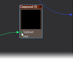
A Compound node is a container for other nodes, or networks of nodes, simplifying complex networks and making for easy reuse. The easiest way to understand it is with a quick example.
Double-clicking on the Compound node will enter a new Node editor with Compound as its title. You will see two nodes, an Input and an Output. If you have dragged an output to the Compound already, the Input node inside the Compound Node editor will show it as an output. A nodal network can be built inside the Compound Node editor and when either the Compound’s Input or Output nodes are double clicked you will be returned to the main Node editor.
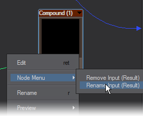
Inputs to the Compound node can be renamed by right clicking on the entry. Renamed entries are also renamed inside the Compound node window.
You can rename the Compound node and also use the notes function to make its function more understandable. Double clicking to enter the Compound will put Compound in the title bar.
Example - Simplifying the Benchmark Marbles nodes
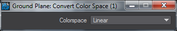
Convert Color Space
For use with images that are already profiled, pipe the image's color output through the Removed output to linearize them. Or if your images are linear use Applied to add the color space selected in the node's interface.
Why is this handy? Assuming you're using the sRGB preset, then the Color Constant node will be supplying the linearized version of the color on its output connection (it removes the Picked Colors space). Something like a vector node does no such conversion therefore connecting a vector node to a material's Color input will produce a brighter color compared to the Color constant node with the same numerical values. Pipe the vector node through this node and "remove" the same space as Picked Colors and they'll then match.
EdgeShader
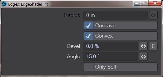
 The edge shader will perform a rendertime smoothing of hard geometry edges. It's not a replacement for good modeling, but it will create a smooth appearance for less important scene items. The controls are:
- Radius - the size of the rounding effect. The default is 10 mm, and while you can go bigger, the effect quickly becomes unrealistic depending on the scale of your object
- Concave - The Edge shader acts on concave edges by default
- Convex - The Edge shader acts on convex edges by default
- Bevel - Add a straight bevel to an edge. The field determines what percentage of the created edge is a hard bevel
- Angle - The Edge Shader will only work on edges between polygons that are at an angle greater than this field. The default is 15 %
- Only Self - If you have multiple objects or surfaces using the Edge Shader, and they encroach on each other's position, the Edge Shader will smooth over the join unless this option is checked
Limiter
The Limiter node clamps each channel of the input color between the user-specified low and high limits. Therefore, none of the Red, Green, or Blue components of the input color will be output as being lower than the value specified by the Low input. Conversely, none of the Red, Green, or Blue components of the input color will be output as being higher than the value specified by the High input. Imagine three Clamp nodes each with the same limits placed on the red, green, and blue components of the color.
Make Color
The Make Color node allows a color to be constructed using three scalars. The scalars used are input on the Red, Green, and Blue inputs, respectively, and must each vary between 0.0 and 1.0.
Make Vector
The Make Vector node allows a vector to be constructed using three scalars. The scalars are input on the X, Y, and Z inputs, respectively.
Mixer
The Mixer node allows two colors to be mixed based on a scalar using the standard nodal blending modes. In other words, it can be used to composite two colors. The Fg Color is mixed with the Bg Color using the Opacity as the alpha component for the mix. The two colors will be mixed based on the selected Blending mode. For more information about the blending modes see the Common Input and Outputs section. The mixed, or blended, color will be output on the Color output, while the Alpha output is driven with the value used for the opacity input.
Occlusion
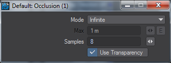
Occlusion is a shading method that looks at how accessible areas of a polygon are to ambient light. It is not as accurate as true radiosity, but much faster to calculate and can be used as a "dirt shader". There are two modes - Infinite and Range. Ranged can be driven by a distance or a node.
Patina
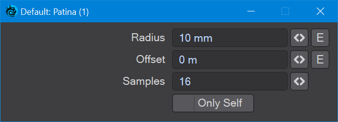
The Patina node can add Wear (a convex shader) to a surface, or Dirt (concave) based on a radius and offset. The fields are as follows:
- Radius - The area to be used for the Wear and Dirt outputs
- Offset - Offsets the evaluation position to get rid of artefacts if encountered
- Samples - The number of samples to use for Patina
- Only Self - Hits are only from only occlusion by the geometry in the same object with the same surface
The Patina offset will correct shading artefacts by offsetting the evaluation position
Demonstration of Only Self toggle use with two objects
Random Integer
Creates a random integer based on the Seed value input either in the Edit Panel or from an integer input connection.
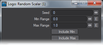
Random Scalar
Creates a random scalar value based between the Min and Max Range in the Edit Panel. These ranges can also be enveloped and the Edit panel offers switches to include the Min and Max values.
Random Vector
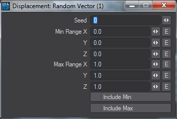
Like Random Scalar, but for vectors.
Vector Scalar
The Vector Scalar node allows a vector to be converted into a scalar. Double clicking the node will present a dropdown list of modes that determine how the conversion occurs. These are:
- Maximum - outputs the scalar as the largest of the three vector input components.
Scalar = Max(X, Y, Z) - Minimum - outputs the scalar as the smallest of the three vector input components.
Scalar = Min(X, Y, Z) - X Channel - outputs the value of the X component of the input vector.
Scalar = X - Y Channel - outputs the value of the Y component of the input vector.
Scalar = Y - Z Channel - outputs the value of the Z component of the input vector.
Scalar = Z - Length - outputs the length of the input vector.
Scalar =Length(X, Y, Z)