Move, Rotate and Scale Parts in LightWave 2019
 LW2018_parts_tutorial_content_03.zip
![]()
The ability to natively move parts around with nodal displacement was added in LightWave 2018. Additionally, the modifier stack brings a lot of flexibility to nodal animation. You can have multiple instances of nodal displacement, which makes organizing, simplifying and reusing nodal displacement easier than it ever was.
Newtek introduced the Mesh Part node - a part is a polygon or group of polygons that share common points. A cube is a part that consists of 6 polygons and 8 points. The Mesh Part node allows you to set up nodal displacement networks that can move, rotate and scale all the connected points within a part as a single unit. In this tutorial I am showing some node setups that I have used to control parts.
Move, Scale and Rotate Parts
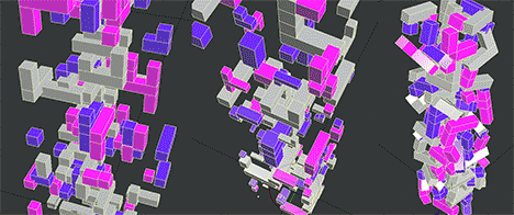
Animated gif showing parts being moved, scaled and rotated
Move Parts
The Mesh Part node provides information about the part that each point in connected to. This allows each point in a part to be transformed in the same way as all the others. In this node setup the part positioned is scaled so that all the parts move away from a common center.
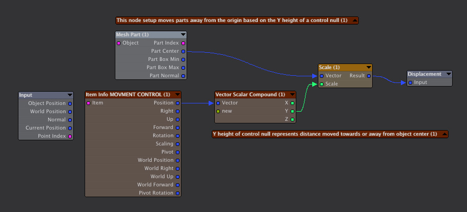
Node setup showing how to move parts away from the object center using the position of a null to control the animation
Scale Parts
In this example the part center is subtracted from the current position of the point that is being evaluated. This, in effect, moves the part to 0,0,0 for scaling purposes.
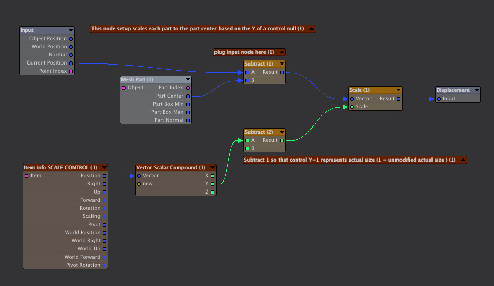
Node setup showing how scale each part
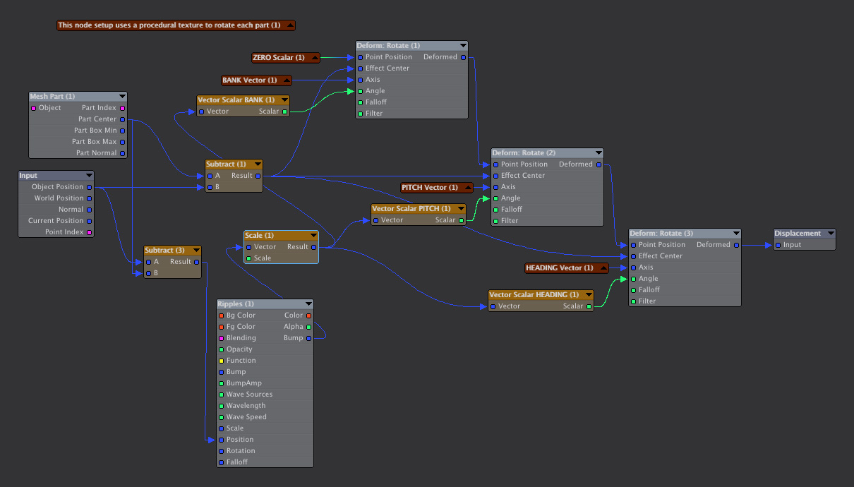
Rotate Parts
A node new to Lightwave 2018 was the Deform: Rotation node. I am not sure I understand exactly how this node works. Perhaps there is a way to use it to accomplish a rotation in one step but I wasn't able to get that to happen. With some trial and error I did manage to put together this node network that will rotate a part around its center.
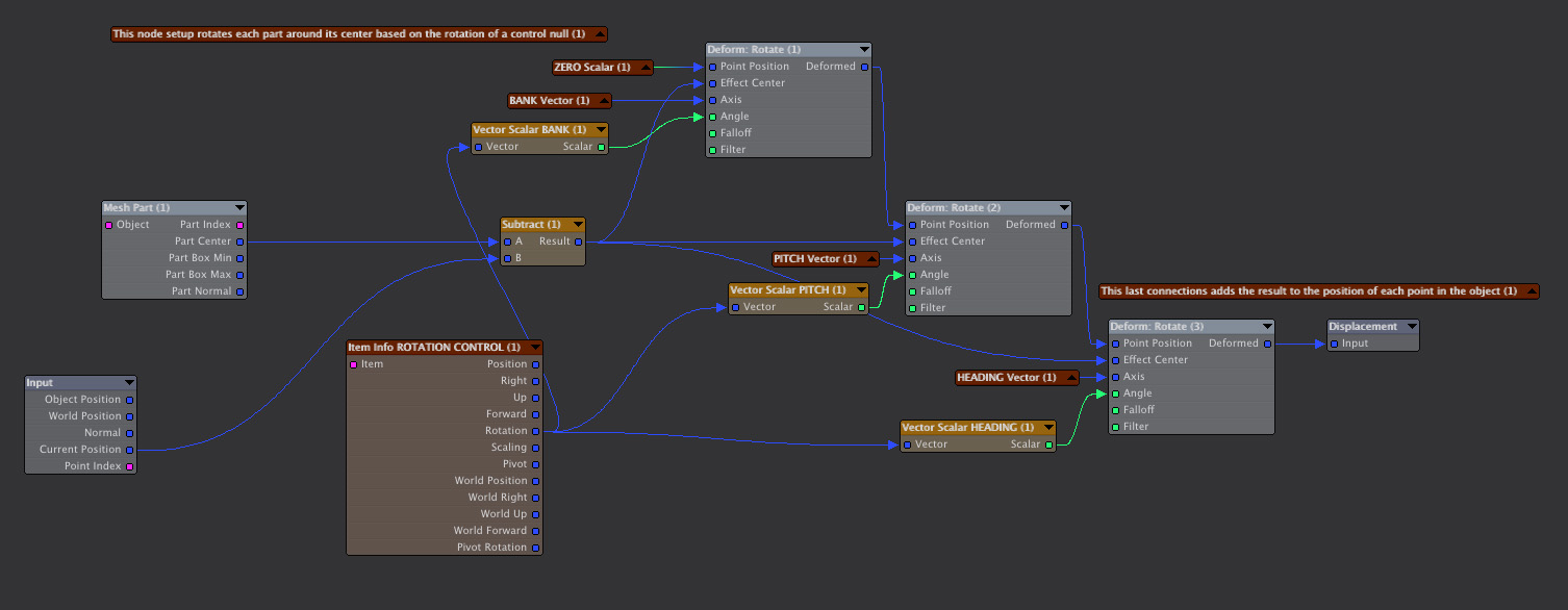
Node setup showing how rotate each part
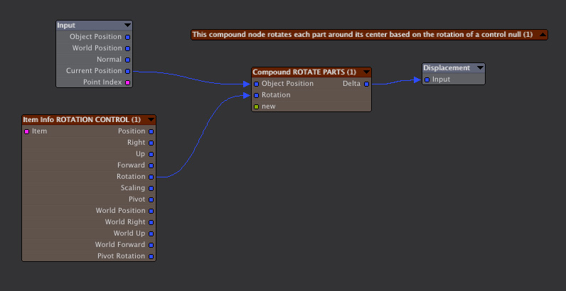
The same node network as the one above but the rotation network is in a reusable compound node
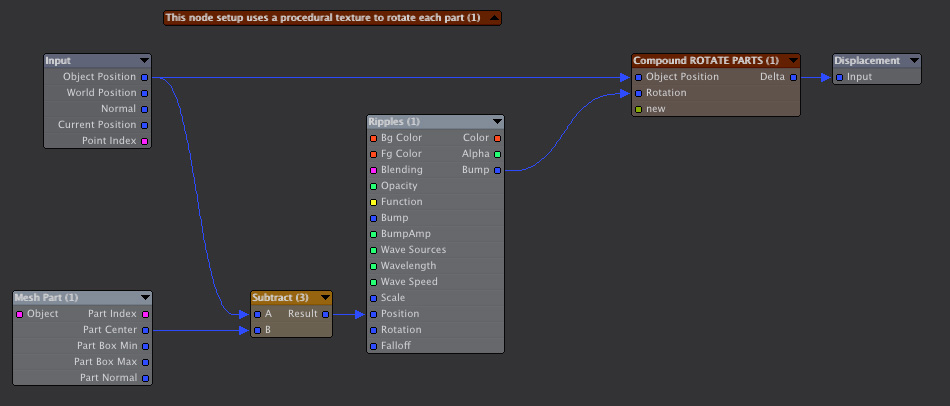
Using a Procedural Texture to Move, Scale and Rotate Parts
In these examples, a procedural texture is used to animate the parts. To keep the example simple I used the Ripples texture which is animated automatically. Other procedural textures can be animatied by linking them to a texture reference null.
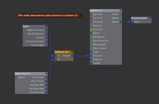
Node setup showing how move parts based on a procedural texture
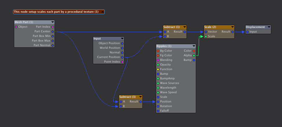
Node setup showing how scale parts based on a procedural texture
Node setup showing how rotate parts based on a procedural texture
Documenting Node
This node network uses an unconnected node as a label to explain the setup's purpose. Also a complicated looking portion has been sequestered into a compound node
Say you have a project where you need to create a certain displacement effect. You have an idea for how to set up nodes to do this. You start with a few nodes and experiment by adding nodes and connecting them in different ways. You might add connections that make perfect sense to you in your gestalt of creation. Finally you get it to working the way you want and you move on to the next project. But the next time you look at it months or years later it is an opaque tangled mess. I’ve had the experience of looking at node networks I set up in the past and have no memory of how they work. For me, once a network gets to a certain level of complexity it becomes very hard to understand. Sometimes I have found it easier to re-create something from scratch rather than trying to figure how a messy network works. That is why I think it’s very important to document your node networks:
- Give node’s descriptive names. You can do this by selecting the node and pressing the N key. Then you can change the name of the node. I like to leave the original name of the node in place so that you know what type of node it is and add a simple description after that.
- Use disconnected nodes as labels to describe the overall purpose of the network and also label individual sections. You can also use the note field at the bottom of the node window, but I find this less useful as you don't see the note until you select a node.
- Encapsulate different parts of your node network in compound nodes if possible. This simplifies the look of the network.
- Keep node networks as simple as possible. The simpler they are the easier they are to understand and reuse. That’s why Lightwave 2018’s displacement stack is such an improvement. A stack of simple nodal displacements can add up to a complex animation.
- Once you have a useful setup working save it as a separate scene. I have saved a library of scenes that contain possibly useful nodal displacements.
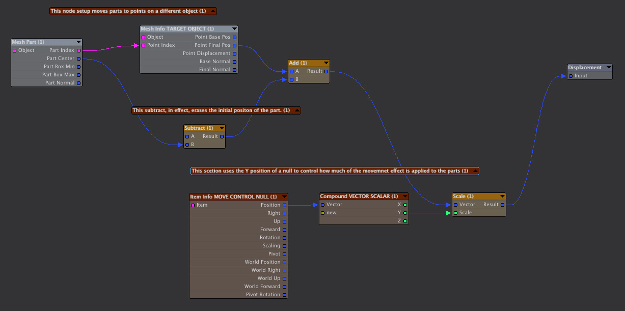
Moving and Rotating Parts to Align With Points on an Object
Moving Parts to Points
One important thing to note is that when you plug a node network into the Displacement node the results of your nodal calculation get added to the position of the points in the object. So, to erase the initial position of the parts, you should subtract the part’s positon from zero as show in this example. This allows the rest of the node network to explicitly set the position of each part.
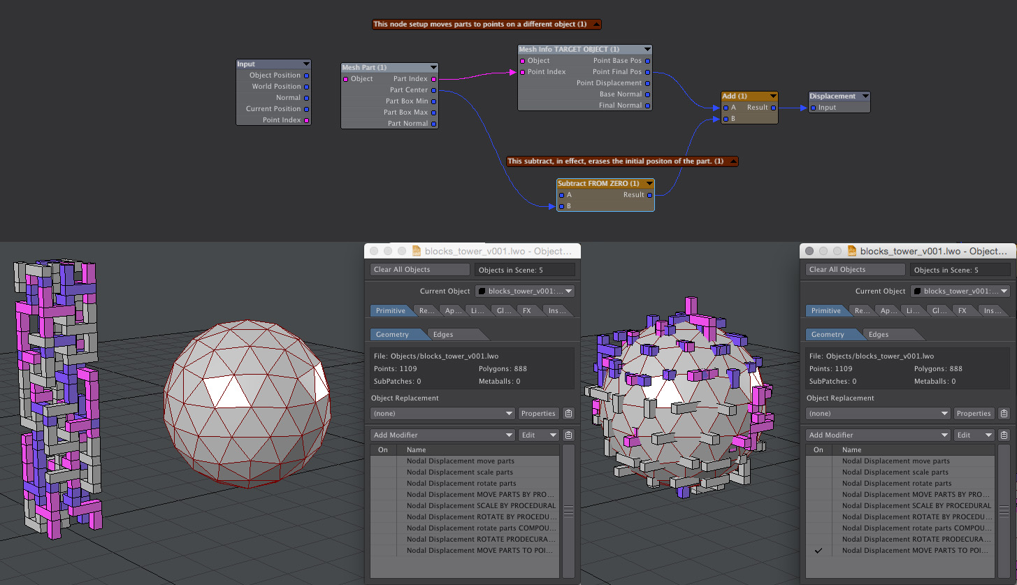
This node setup moves parts to points on a reference object
Rotating Parts to Align with Point Normals
Unlike Lightwave’s instancing, which has aligning to object normal built in, we have to do some trigonometry if we want parts to line up with an object’s normals. I put together an ArcTan2 function as a compound node which calculates an angle given an x and y coordinate on a Cartesian plane. This function is a nodal implementation of the ArcTan2 description in Wikipedia. The node setup is probably very inefficient because it calculates six possible answers then uses the logic node to erase the five incorrect ones. Note that in this example the parts are moved to the points by the node network above. The rotation happens in a completely independent Nodal Displacement.

This node setup rotates parts to align with point normal. Note that the compound node ARCTAN2 is used twice. This function does not exist in Lightwave nodes (there is a third party Math nodes collection with ArcTan2 and many others here). So if all the wiring in that node were out in the open, so to speak, then the node network would look very complex and much harder to understand
Controlling Parts Animations
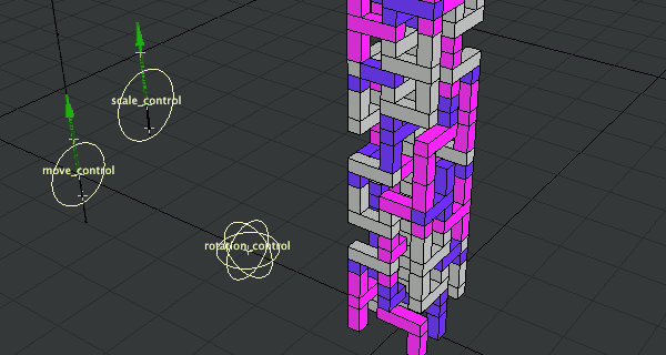
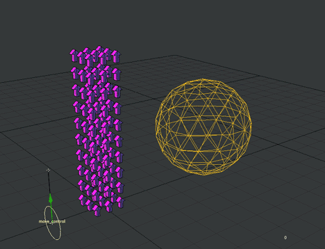
Controlling the Animation of Parts using Reference Nulls
I find using the animation of nulls to control nodal displacement networks to be very useful. This example has a simple animation setup. The move control can be animated between zero and one on the Y axis. This value is used to scale the effect of moving parts. If Y is zero then it wipes out the nodal calculation leaving the parts in their base positon.
Using one reference null to control animation
Using two Nulls to Animate Parts over Time
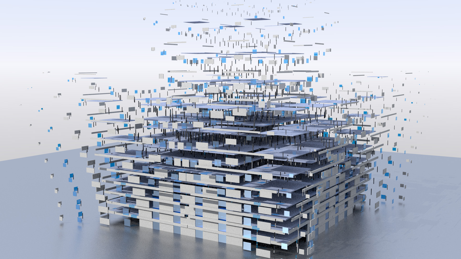
Animating from one state to another is fine but sometimes you need a more complex animation. Very complex animations can be created by getting parts to be displaced at different times. A setup using two control nulls can achieve this. In this example a building assembles itself as parts fly in and scale as they move into place. The Y positions of two control nulls are used to control the animation. Parts above the top null are invisible because they are moved away from their real position and scaled to zero size. Parts below the bottom control null are in their base position. Parts in between are in a blended state.
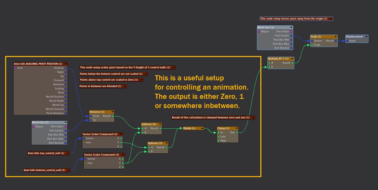
Using Multiple Nodal Displacements
In Lightwave 2018 you can have multiple instances of Nodal Displacements. This let you keep your networks organized and understandable. You can easily make copies of your networks to make changes, layer different animations and effects and to experiment with alternate versions. By referencing control nulls the various nodal animations can be synchronized.

Effects like this are easily achieved with a mix of Part Move node setups
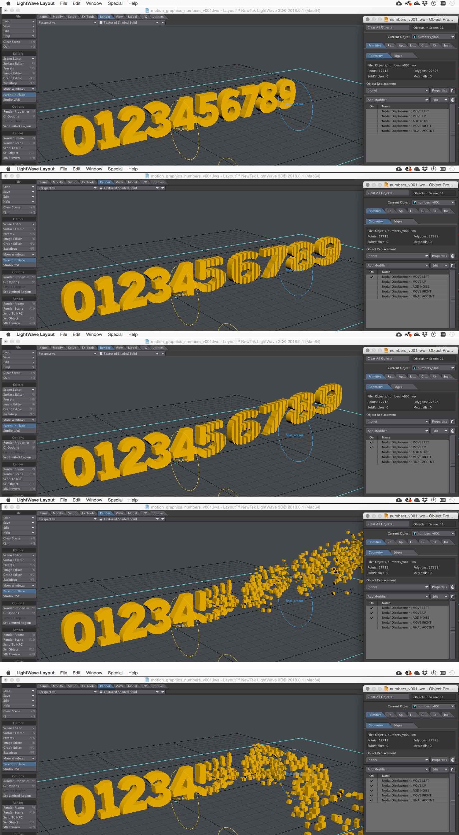
This animation is accomplished by layering five different Nodal Displacements
Using Procedural Textures to Control Animations over Time
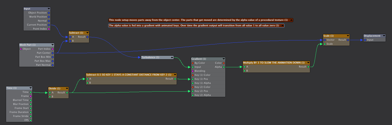
You can use procedural textures as a basis for animating parts at different times. This node setup moves parts away from the object center. The parts that get moved are determined by the alpha value of a procedural texture. In this example the Time node is used as input for the animation. The time controls the position of a gradient’s alpha value keys. Over time the gradient output will transition from all value one to all value zero.
![]()
Conclusion
I have had fun exploring the new possibilities for using deformations in Lightwave 2019. You can download all the content for the examples from this link:
LW2018_parts_tutorial_content_03.zip
-Joe Lertola