Extend - More
This group contain tools that are no longer so required, but could still prove useful in the right circumstances.
Edge Bevel
Edge Bevel is a tool for rounding or splitting edges. It can be used in either point, edge or poly mode. In point or edge mode, the edges, or the edges that are defined by selected points, will be split (beveled). In poly mode, only the outer edge of the selection will be split.
Select Edge Bevel (Multiply > Extend > More > Edge Bevel) to Bevel selected polygons or edges (by point selection). The Bevel can be adjusted by scrubbing in the interface or by using the numeric window. Further adjustments can be made until the tool is dropped (space bar).
You can bevel edges on multiple layers at once and the bevels will be on the same layer as the original polygons.
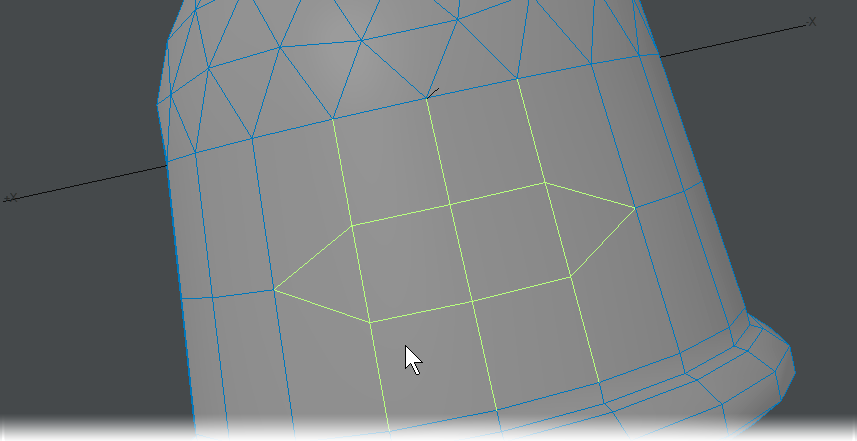
Steps for beveling an edge:
- Choose the edges you would like to bevel.
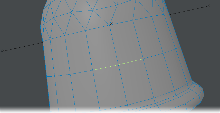
- Choose Multiply > Extend > More > Edge Bevel and adjust the Move setting.
If only one point is selected, nothing will happen when the tool is run (it’s an Edge Bevel tool, not a Point Bevel tool)
If all or no polygons are selected (in poly mode), the tool will do nothing because it bevels only the outer edge of the poly selection. If they are all selected, there is no outer edge.
If you want to round the edges on a cube that is higher resolution, select only the edges of the cube, not any of the points between edges.
Use the Preview Mode on slower machines to speed up interactivity. To use the tool in Preview Mode, make selection first and then choose Edge Bevel from the Multiply Tab. To adjust size of bevel, click and drag on screen. When it is at the desired position, right click and it will set it. The size of the bevel can still be adjusted more if needed or if finished, just drop the tool.
Edge Bevel will give unpredictable results if the points selected have missing adjacent polygons.
Edges that are not in the outer edge category can also be split. Selecting any two or more points in a row will define an edge to be split. Therefore, on outer edges, the hard corners will become soft, on inner edges, the edges will be split but stay on their current plane.
Create Rows
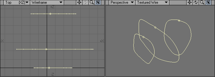
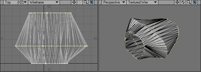
Creates a row of polygons based on the first row of selected points and the last selected point. The order of selected points on the first row does not affect the tool.
The first row of points is selected then the last point. The first row determines the number of polygons created. The first and last point selected determine the edge of the first polygon. In step 3 the last point selected was at a different angle and so the "fin" was extruded at an angle. 4 shows multiple rows can be selected. Here, all points on the original grid were selected before the last point.
Extender Tool
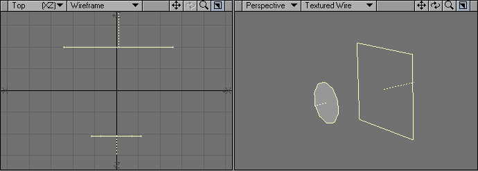
This tool has been superseded by Extender Plus. The Extender command (Multiply > Extend > More > Extender) clones selected points and creates new geometry connecting the original points and the clones. Essentially, Extender is like using Smooth Shift with 0 Offset, except with points instead of polygons.
Steps for extending points (edges):
- Select the points that make up the edge you would like to extend. Remember to select the points in order and counterclockwise.
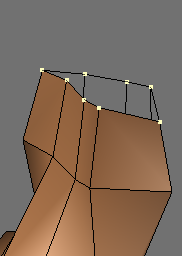
- Choose Multiply > Extend > More > Extender , then move the selected points away from original points.
In Subpatch mode, newly created geometry will be in Polygonal mode. Extender Plus doesn’t have this limitation.

Selecting the points out of order may have unwanted results.


Left: Points selected in order, counter clockwise. Right: Same points selected randomly.
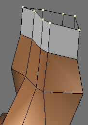
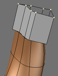
Rail Bevel Tool
Rail Bevel (Multiply > Extend > More > Rail Bevel) is a very fancy beveling tool that works in a similar manner to the normal Bevel tool. Dragging your mouse left/right adjusts the new bevel geometry’s distance from the original polygon. Dragging up/down adjusts the inset direction (towards or away from the polygon’s center). The Ctrl key constrains the change to a given degree of freedom - just like the normal Bevel tool.

The difference between Rail Bevel and Bevel is that Rail Bevel uses a profile from a background layer to generate several bevel operations in a single step.
The profile is a series of points you create. They can be unconnected, or part of a polygon or curve. The only important factor is point order, which is normally determined by their order of creation.The profile is treated as if it were oriented based on the polygon’s plane and extrudes along the direction of the polygon’s normal.
Each point in the profile is treated as a bevel. X=Inset, while Y=Length.
Steps for using Rail Bevel:
- Create some geometry in a layer that you plan on extending.
- In a new layer create a curve with the profile you would like to use for your bevel. Your profile must be created in the Back/Front viewport to work.
Place the curve in the Background layer and your object in the Foreground layer. Select the geometry you would like to bevel.
Click and drag to create your bevel. Dragging your mouse left/right adjusts the new bevel geometry’s distance from the original polygon. Dragging up/down adjusts the inset direction.
Press the Enter key to confirm.
The placement of the curve has no effect on the final outcome.
New geometry inherits VMap and face/curve properties of the original polygon.
Rail Bevel works with multiple polygons selected.


If you have multiple profiles in different layers, you can apply them one after another by selecting them (one at a time) as the background layer while using Rail Bevel.
Router Tool
The Router tool (Multiply > Extend > More > Router) will create custom beveled Edges. The numeric window will come up as soon as you select Router and will give you several options to work with.

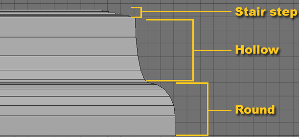
Router has three bevel types to choose from: Round, Hollow, and Stair Step.
Round: This option will create a “convex” curve profile.Hollow: This option will create a “concave” curve profile.Stair Step: This option will cascade the newly created geometry.
- Depth - Adjusting the Depth setting changes the Height of the newly created geometry.
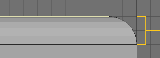
- Edge Width - Edge Width controls the Inset of the bevel.
- Steps: Adjusting the Steps setting will change the number of segments created

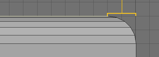
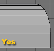
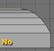
- Bevel on Corner?: Choosing Yes (Default) will constrain the bevel curve to the Depth and Edge Width settings. Choosing No will use the Depth divided by the number of Steps to configure the curve along the edge
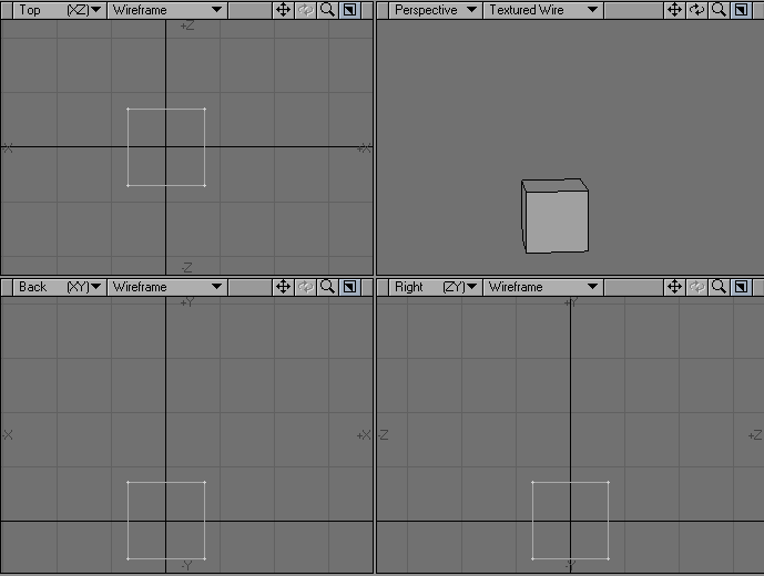
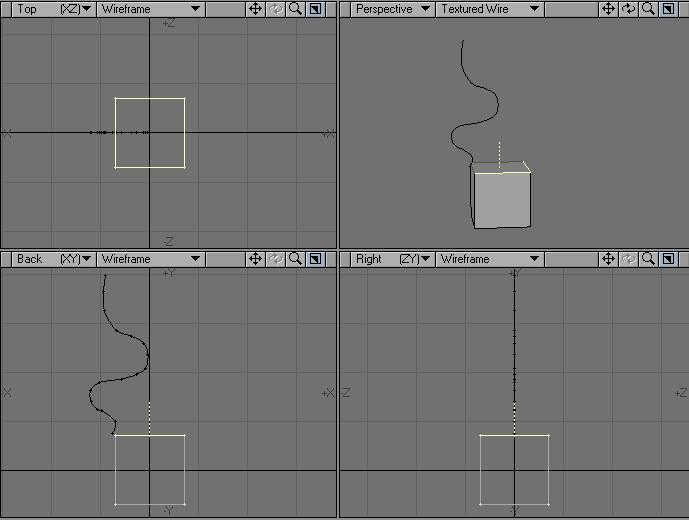
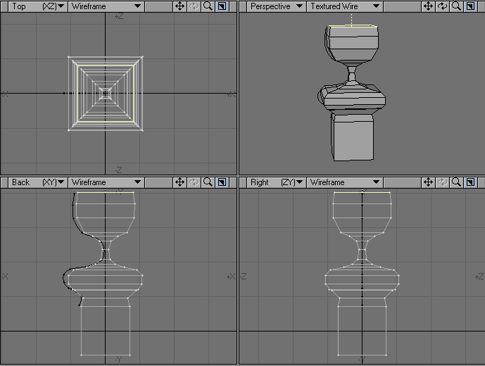
Motion Path Extrude
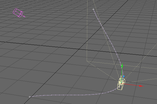
Motion Path Extrude (Multiply > Extend > More > Motion Path Extrude) will extrude geometry along a motion path saved out of Layout.
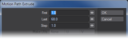
- First - This option defines the first frame in the motion file that will be used.
- Last - This option defines the last frame in the motion file that will be used.
- Step - This option determines how many segments will be used in the extrusion, by setting a sampling ratio relative to the number of frames of the motion path. The lower the number, the more segments.
Step Examples:
First Frame 1, Last Frame 60, Step 0.5 - 120 Segments
Step 1 - 60 Segments
Step 2 - 30 Segments
Step 3 - 20 Segments
Make UVs Option
The Make UVs option at the bottom of the numeric panel assigns some default UVs based on the geometry of the object. Note that a UV Texture Map must be currently selected or this option will be ghosted.
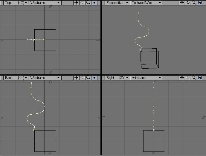
Steps to extrude along a motion path:
- Create a motion path for an Item in Layout.
- With the item still selected go to File/Save/Save motion file. Be sure the file has the .mot extension.
- Open the Modeler and create an object.
- Select Motion Path Extrude ( Multiply > Extend > More > Motion Path Extrude ). Select the path saved above and change settings in the numeric window as needed.
- Click OK.
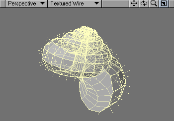
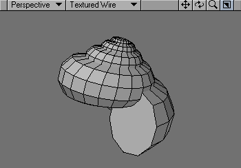
Seashell
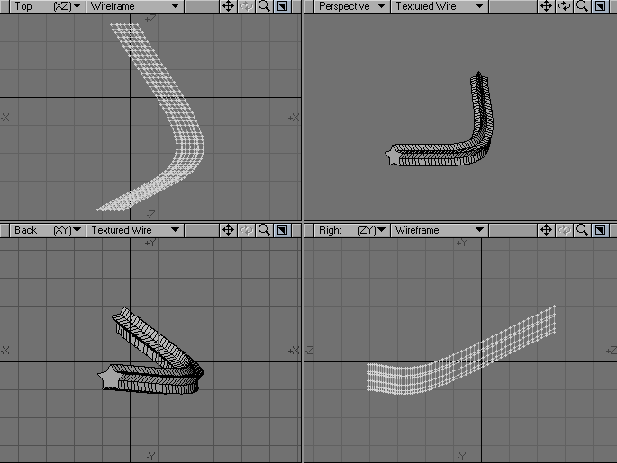
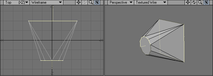
The Sea Shell tool (Multiply > Extend > More > Sea Shell) lets you interactively make seashell shapes. Essentially, this is like using the Lathe with a scaling factor on an object.

Open the numeric panel to set options.
- Axis - the perpendicular axis around which the shell is twisted.
- # of Loops - the number of times the source polygon is twisted fully.
- Sides per Loop - is the number of segments to use per loop.
- Shift per Loop - controls the vertical shifting of the loop.
- Scale per Loop - the scaling factor achieved after each loop.
Make UVs Option
The Make UVs option at the bottom of the numeric panel assigns some default UVs based on the geometry of the object. Note that a UV Texture Map must be currently selected or this option will be ghosted.
Steps for using the Seashell tool:
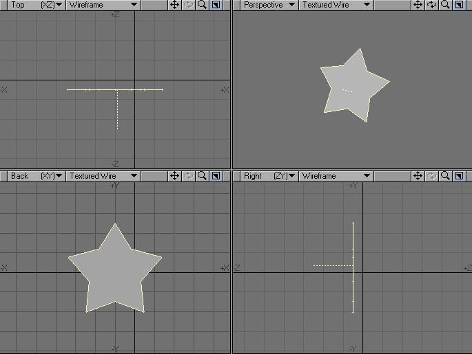
- Create a flat polygon that you would like to apply Seashell to.
- Choose Multiply > Seashell and set the options to your liking.
- Press Enter on the keyboard.
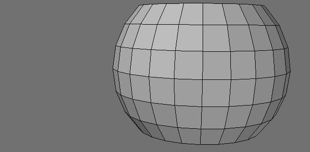
Spikey Tool
The Spikey tool (Multiply > Extend > More > Spikey) subdivides the selected polygons and moves the center point out in the direction of the surface normal giving a spiked appearance. Simply select the tool and drag your mouse pointer in a viewport.
Steps for using Spikey:
- Create an object that you would like to use Spikey on.
- Choose Multiply > Spikey , and open the numeric window.
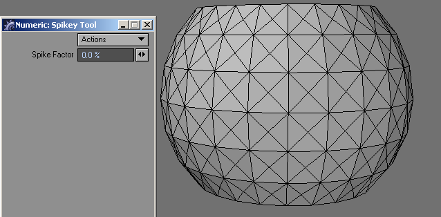
- Left click and drag in the viewport or use the Spike Factor input field on the numeric window to adjust the spikes.
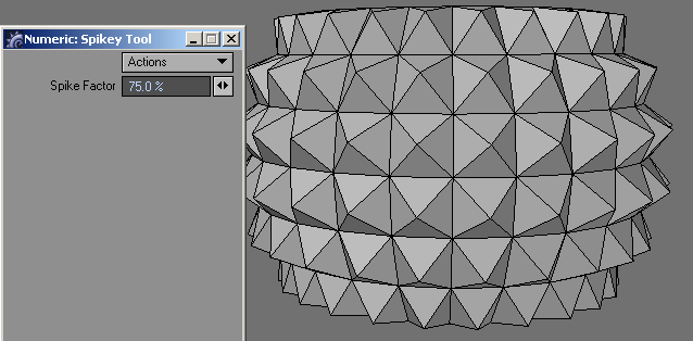
- Press Enter to confirm the changes.
Using Spikey with a Spike Factor of 0 is a good way to subdivide a polygon for deformation.
Create Skin
With the Create Skin command (Multiply > Extend > More > Create Skin), you can cover a series of polygons or curves with a polygon skin. The shapes do not need to have the same number of points in common. This is also called lofting.
- Select the geometry to be skinned.
- Choose Multiply > Extend > More > Create Skin.
The polygons or curves must be selected (or created) in the order that you want them connected.
This operation can only operate with elements from the same layer.
Create Skin works best when you use single-sided polygons for the framework. Double-sided polygons can result in strangely skinned objects.
If you skin using curves, the curves will remain in the Modeler workspace following the operation. However, they do not become part of the resulting skinned object.
Although Create Skin is similar to the Make Spline Patch command (Construct > Patch), which uses curves, the difference between the two commands is significant. The Make Spline Patch command tends to follow smooth contours, which maintains a rounded surface. Create Skin tends to connect curves with straight-line segments, which creates less smooth profiles.
Morph Polygons
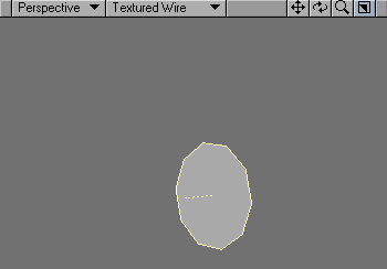
The Morph Polygons command (Multiply > Extend > More > Morph Polygons) will create a number of connected intermediate polygons between two selected polygons or curves that have the same number of points. They will have an outer surface, as if you also used the Skin command on them.
- Select the two polygons/curves that you would like to skin.
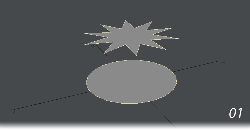
- Choose the Morph Polygons command ( Multiply > Extend > More > Morph Polygons ) and set the number of segments and click OK.
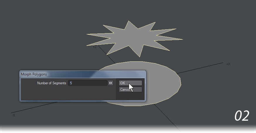
- The result is
Morph Polygons works best when you use it between single-sided polygons.
To get a twist effect, rotate the source or target polygon a little.
If you morph using curves, the curves are treated as straight-edged polygons, and will morph in a linear fashion. The curves also remain in the Modeler workspace following the operation, although they will not be part of the morphed object.
The Number of Segments field defines the number of morphed steps you desire between the two selected polygons.
As with the Morphing function in Layout, the Morph Polygons command is dependent on point order. As such, you should create the source and target from the same polygon. You may need to flip some polygons after using this command.