Expressions
Introduction
Expressions are an advanced LightWave 3D feature that uses mathematical formulas to modify the value of any animation channel. Expressions let you make the motion of scene items dependent on other item motions or factors in a scene. You could, for example, force an object to stay between two other objects, keep feet from going through the floor, or even control the entire posture of a character based on its feet! The possibilities are endless.
There are two types of expression, "Bracket" expressions and "LScript" expressions. Each has their advantages and disadvantages. Bracket expressions take their name from the fact that the channel they are reading is always enclosed in square brackets, "[" and "]". The LScript expressions have a syntax similar to that of LScript. You can use much of the LScript documentation to help with the use of the functions available for using in LScript expressions.
You can obtain a reference of available functions from the LScript documentation or from Expression Builder.
Graph Editor: Expressions Tab
Expressions are built right into the Expressions Tab on the Graph Editor. This implementation has several advantages over the channel expression modifier. First, expressions are not an attribute for a single channel. Instead, the expressions stand alone and channels are attached to them. This allows you to attach multiple channels to a single expression! Moreover, you can save and load libraries of expressions you create.
To get interactive updates in Layout for expressions, make sure you have Auto Key active.
To create an expression:
- Click the New expression button. No channels need to exist in the Channel Bin nor does any channel need to be selected-expressions stand alone.
- Enter a name for your expression in the Name field.
- Enter your expression in the Value field.
You may also copy the selected expression by clicking the Clone button. This creates an independent copy that you can alter.
Additive Expression
You can use the Value variable to make an additive expression. Value is equal to the (base) keyframed value. For example, if the camera's keyframed X position was 2m and the Light's keyframed X position was 3m, the expression Value + [Light.Position.X], placed on the camera's X position, would move it to 5m.
Note that editing an item in Layout with an additive expression attached (e.g., Value + [Null.Position.X]) can cause recursive updates, since you're changing the Value. There are a few work-arounds:
- Do the edit in the Graph Editor;
- Turn off the expression in the Graph Editor. Perform the edit and then turn it back on; or
- Add a null and animate it the same way as the item itself (except without the expression). Then, replace Value in the expression with the null's corresponding channel (e.g., if Value was the item's Y position, then use the null's Y position instead).
To rename an expression:
- Make sure the expression is selected. Its name will appear in the Name field. To select a different expression, choose it from the Expressions... pop-up menu.
- Type a new name into the Name field. This will have no effect on any of the expressions channels.
To attach an expression on a channel:
- Make sure the expression is selected. Its name will appear in the Name field. To select a different expression, choose it from the Expressions... pop-up menu.
- Select the channel(s)in the Channel Bin.
- Click the Apply button. The modified dot (•) will appear to the left of the channel name in the Channel Bin. The expression must be legal, of course.
It is possible to attach multiple expressions to a single channel, but this is not recommended. The expressions will be evaluated in the order they were attached; however, there is no way to determine that order.
To determine what channels are attached to an expression:
- Make sure the expression is selected. Its name will appear in the Name field. To select a different expression, choose it from the Expressions... pop-up menu.
- Click the Get Channels button. The contents of the Channel Bin will be replaced with the channels attached to the current expression.
The name of an expression on the Expressions... pop-up menu will list the number of channels attached to it in parentheses.
To remove a channel from an expression:
- Select the channel(s)in the Channel Bin.
- Click the Remove button.
Libraries
You can save all of the existing expressions to a file on your hard drive by choosing Expressions... > Save Library. To load a previously saved library, choose Expressions... > Load Library. If an expression exists with the same name, it will be replaced. Otherwise, the library of expressions will be added to the list.
You can clear all unused expressions by choosing Expressions... > Clear Unused. This clears out any expressions that do not have any channels attached.
Expression Syntax
LightWave supports two types of expression syntax. The first is identical to the Channel Expression syntax (e.g., the x position of a light at time t is given by Light.pos(Time).x). This works normally, as does all of the control syntax (x < 5 ? y : -y).
With integrated expressions, you can also use a bracket notation syntax to reference any channel in the system. By placing square brackets ([]) around a full channel name, you may access any channel in the system. This includes MorphMixer channels, envelopes, and so on (e.g., [Camera.Rotation.H]). You can freely mix and match the two methods of referencing item information ([Light.Position.X] and Light.pos(Time).X).
Channels referenced in this way will be evaluated in a dependency-conscious way. In other words, if channel X references channel Y, which has an expression that follows channel Z, then the bracket notation insures that the Y channel's expression (referencing Z) is evaluated before computing channel X.
Bracket notation expressions may also take an optional time argument. The syntax is [Channel,Time_arg] where Time_arg may be any legal expression, but cannot include anything using the bracket notation syntax. An example of a bracket notation expression that follows the camera's X position, but lags by half a second, would be [Camera.Position.X,Time - 0.5]. To make it lag by four frames, it would be [Camera.Position.X,Frame - 4].
To use bracket notation expressions:
- Add two null objects named Control and Action to an empty scene.
- Animate the Control null on its Y axis.
Attach the expression
[Control.Position.Y]
to the Action null. This would lock the two together on the Y axis; wherever Control goes, Action follows.
Change the expression to
[Control.Position.Y,Time]
. This has the exact same result. As such, unless you want to modify Time, you do not need to use the time argument.
The expression
[Control.Position.Y,Time - 1]
would lock Action to Control, but give it a one second delay.
The expression
[Control.Position.Y,Frame]
also has the same result as the original expression, but differs in that it feeds the time of the current frame to the expression. This lets you do something like:
[Control.Position.Y,Frame - 30]
.
[Control.Position.Y,Time - 1]
and
[Control.Position.Y,Frame - 30]
yield the exact same results (assuming 30 fps). One expression is working with seconds and the other is working with frames.
Make sure you use spaces around math operators, like the minus sign used above. Not doing so may confuse the expressions parser, which allows some of those characters in scene item names. Loops are not allowed and the system will report an error if any are detected.
Bad Expressions
If an integrated expression is erroneous, an error dialog will appear when you attempt to apply it or otherwise exit the input field (e.g., using TAB key, ENTER key, mouse click, etc.). Also, the Apply button will show Uncompiled instead of Apply.
Subexpressions
An expression may reference another expression (subexpression). The format is identical to other bracket notation calls, except that in place of a channel name, you supply an expression name. Time may still be specified, just as if it was a channel reference.
So
[myCenter, Frame - 5]
would cause the system to evaluate the expression
myCenter
at the current Frame - 5 and return that value.
If the subexpression contains a reference to the Value variable, then the current value of the channel - whose expression is using the subexpression - will be used. In other words, all expressions within an expression are using the same Value variable.
Also, subexpressions may not themselves contain subexpressions. There will be no error, but any sub-subexpression will always return 0.0 upon evaluation.
Vector References
Bracket notation references to channels may also reference a vector for position, rotation, or scale. This works with the built-in expression functions that take vectors as parameters.
For example, this expression shows how you could find the center X coordinate of two items using scalar values:
([Left.Position.X] + [Right.Position.X]) / 2.0
Here is an expression that performs the same feat, but using vectors:
center ([Left.Position], [Right.Position]).x
An advantage to the second method is that items with spaces in the names can now be referenced by vector functions.
Expressions Tree
The Scene list area for the Graph Editor has an Expressions Tab. The Expressions tree shows all the expressions in the system. The first column reflects the active state of an expression. You may toggle the expression on and off by clicking in the On column. All attached channels will be affected.
The Attached column shows the number of channels attached to the expression.
Double-click an expression name and the contents of the Channel Bin will be replaced with the channels attached to that expression. You will also select the expression. Hold the Shift key and double-click to add the channels without removing any.
If you right-click an expression name, a pop-up menu appears, allowing you to delete the expression. This will detach any channels that may be using it.
Expression Builder
The Expression Builder is a "wizard-type" feature designed to help you write expressions. To access it, click the Builder button on the Graph Editor's Expressions Tab. This will guide you through setting up a single function as an expression.
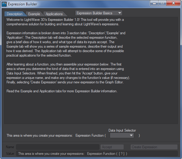
To use, first select an expression function from the Expression Builder Basics pop-up menu at the top.
The Description Tab gives you a description of what the expression is. The Example Tab gives you an example of how to use the expression. The Applications Tab explains why the expression might be used.
Once an expression "template" is chosen you will be presented with a composite of the expression below the info windows where you are presented with pop-up menus to set what values and/or channels are driving each of the components.
Once you've set the inputs, click Accept. You will be able to rename and modify the expression on the lines below. Click Create Expression to add the expression to the Graph Editor's list.
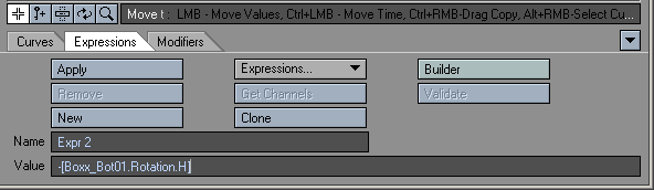
Bracket Expressions - Syntax
Bracket expressions always have the channel reference enclosed in square brackets and have the general syntax as shown in the figure.
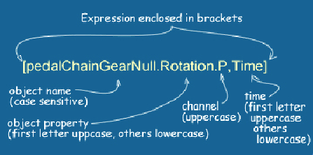
You can also use "Frame" in place of the "Time" and you can also do things like refer to earlier times e.g. [objectName.Position.X, Time – 0.1]
The primary disadvantage of Bracket expressions is that they may only be used via the Expressions Tab in the Graph Editor.
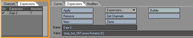
LScript Expressions - Syntax
LScript expression are not enclosed by square brackets. The object property is all lowercase, as is the channel - see the figure below.
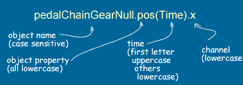
LScript Expressions are generally used via the Modifiers Tab in the Graph Editor, or, more typically, via the Motions Options Panel.
One advantage of LScript expressions applied in the Motion Expressions Panel is that they can act after an IK example.
LScript expressions can also be used to create expression-controlled displacements via the Displacements Panel where the expression can act before or after a bone deformation.
Using Expressions - Examples
Example 1: Expression Basics: Rotating a Gear
William Vaughan says: "I've been using LightWave for many years now and Expressions have always been something that I considered too technical, something that I'd give my math friends to work on. It wasn't until recently that I found out that it's quite simple to use expressions. This tutorial will walk you through setting up a basic expression that will help speed up animating gears on a Mech."
Creating an Expression:
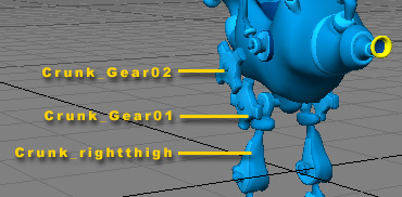
- Load the Crunk scene attached here.
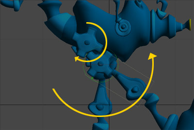
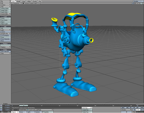 Our goal in this setup is to have the gears automatically rotate when the Thigh "Crunk_rightthigh" is rotated. The lower gear "Crunk_Gear01" is already setup to rotate by being parented to the thigh. We can do this because the lower gear's pivot point is in the same place as the Thigh. The upper gear "Crunk_Gear02" doesn't share the same pivot point and needs to rotate in the opposite direction. You could manually animate the upper gear but using an expression will save you the hassle.
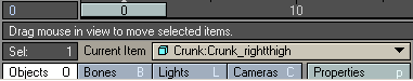
- Select "Crunk_rightthigh" as the Current Object.
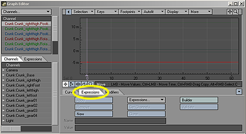
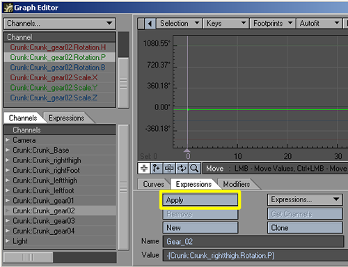
- Open the Graph Editor by clicking on the Graph Editor button, or use the keyboard shortcut of Ctrl F2 .
- Click on the Expressions Menu Tab located under the graph display.
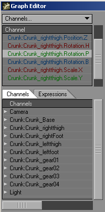
- Click the button labeled "New" and give it a name. I chose to name mine "Gear_02".
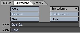
- In the Value field, select "Value" and replace it with "-".
The "-" will make the gear spin the opposite way of the thigh by giving it a negative value.
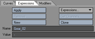
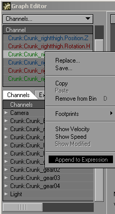
- We want the Gear to spin the opposite way of the Thigh by giving it a negative value of the Thigh's Pitch. The "-" makes it negative, now all we need is the Pitch value of the Thigh. From the Channel List choose "Crunk:Crunk_rightthigh.Rotation.P".
- Right-click and choose Append to Expression.
 The Value Field should look like this:
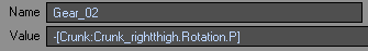
Congratulations! You have just written your first expression. Now that wasn't so hard was it? All we need to do now is apply this expression to "Crunk_Gear02" and we'll be finished with the setup.
Applying an Expression:
- Now that we have our Expression let's apply it to the Gear. From the Channels list select "Crunk_Gear02".
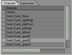
- From the Channel List choose "Crunk_gear02.Rotation.P".
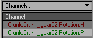
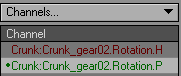
- Click Apply.
A small dot is placed next to the channel to let you know that it has an expression attached to it.
Let's take a look at what happens when we rotate the Thigh.
- Close the Graph Editor window and make sure that Auto Key Create is selected.
- Select "Crunk_rightthigh" as the Current Object, and rotate its Pitch.
Crunk_Gear02 should rotate on its Pitch in the Opposite direction of Crunk_Gear01 and Crunk_rightthigh.
Well, there you have it. Your first expression applied and in action. We've only scratched the surface on the power of Expressions in LightWave.
Example 2: Expression Builder
In this example we will use the Expression Builder to center the hips of a character between its two feet. This example assumes the character's hips are not determined by any form of IK calculation. If that is the case you will need to use LScript expressions (applied via the Motion Options Panel) as only Lscript expressions can act after IK.
Assume the name of the character's two feet are "footLeft" and "footRight" and that the position of the hips are controlled by a single null called "hip". To center the hip null we will fix its X and Z coordinates (and leave the height, Y, to the animator).
Open the Graph Editor and load the hip channels. Click on the Expressions Tab - your panel should look like the figure.
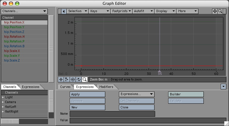
If you select your hip null before opening the Graph Editor the hip channels will automatically be added to the channel bin.
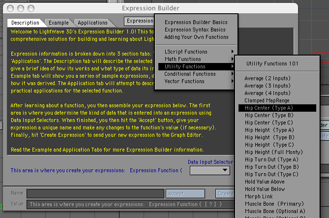
First we will create the bracket expression to center the X coordinate of the hip null. Click on the Builder button to open the Expression Builder Panel, click on the Expression Template button at the top of the panel and select the Hip Center (Type A) menu option as shown below.
This brings up the expression template - all you have to do is say which channels you want to slot into the template. Expression builder will then create the full expression for you and add it to the Graph Editor. The template for hip centring can be seen below.
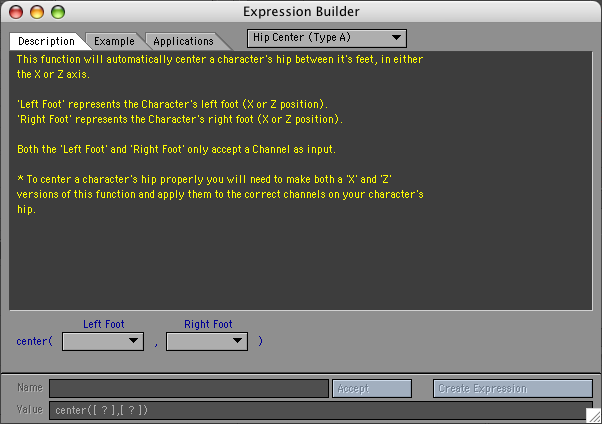
The good thing about the Expression Builder (apart from creating a template for you) is that it also gives an explanation for how to use the expression template. To center the hips we will use the "center" function. This function takes two arguments, the two coordinates between which you want to center the object. The important thing to understand is that the expression can only center in one dimension. To center in two dimensions (ie. the X and Z coordinates) we use the expression twice. Once to center the X coordinate and a second time, using the Z coordinates, to center in the Z direction.
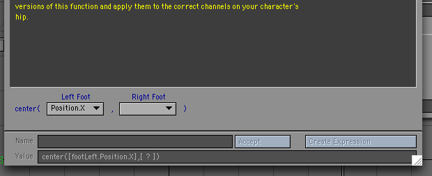
Back to the Expression Builder template First for the X direction. We need to enter the X position of the left foot and the right foot. To do this for the left foot click the Left Foot pop up menu button and select the Channel option to bring up the Channel Selection Panel as shown:
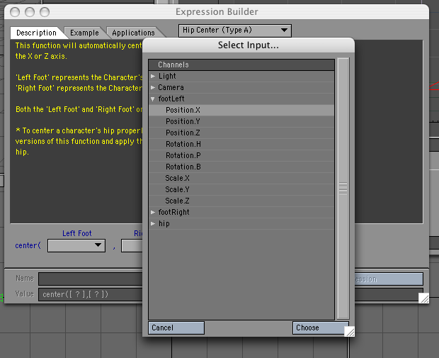 and then select the "Position.X" of the footLeft object. Click Choose and you should notice that the X position channel of the footLeft object has been entered into the expression (which is written in the "Value" field on the panel) as shown:
 Do the same for the "Right Foot" pop up menu, but now select the Position.X channel for the rightFoot object. The Expressions Builder Panel should now look like this:
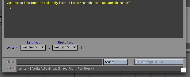
Now, click the Accept button to accept the expression. Expressions Builder gives the expression a name in the Name field - usually something like "newExp_2" - delete this and replace it with something meaningful like "centerHips_X". Finally, click Create Expression - this tells Expressions Builder to enter the expression in the Expression fields in the Graph Editor. Close Expressions Builder and the Graph Editor should now contain your expression as shown below.
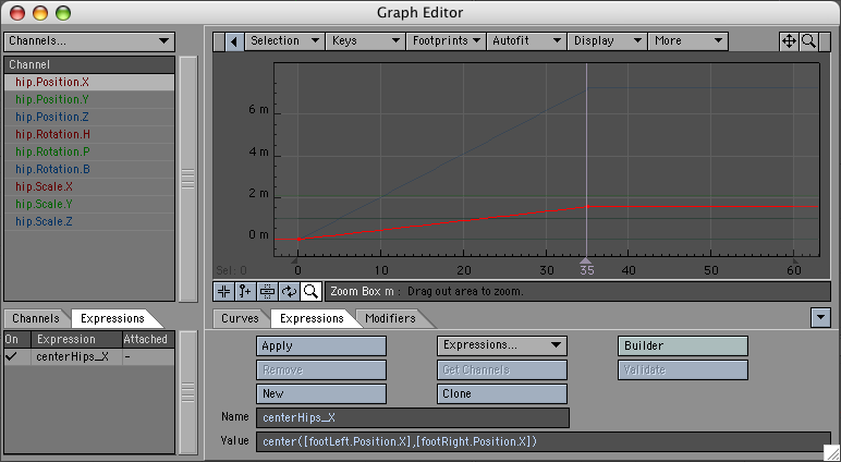
In order for the expression to actually affect the X coordinate of the hip object we need to "Apply" the expression the X channel of the hip object. To do this select the "hip.Position.X" channel in the channel bin and then click the Apply button. The hip.Position.X channel should then have a dot to the left of the name to show that that channel has an expression applied to it. If you have the Always Show Modified switched on in the Graph Editor options then as soon as you apply the channel the modified curve will appear in the curve window as shown:

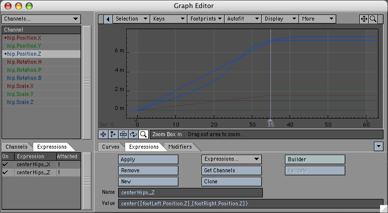
We still have to center the Z coordinate of the hip object. To do this you could use the Expression builder again (choosing the Position.Z channels for the foorLeft and footRight template slots), however, there is a quicker method. Since the expression for the Z coordinate is similar to the X coordinate we can create it by "Cloning" the centerHip_X expression. You do this by clicking the Clone button (on the Expression Tab of the Graph Editor). This will create the same expression, but with the new name "centerHip_X (Clone)". All you need to do is edit the expression name – change it to something like "centerHip_Z" and then change the X's in the actual expression to Z's. Then select the hip.Position.Z channel in the channel bin and click "Apply" to get:
Your hips will now remain centered between the character's feet no matter what the feet do.If you look at the Utility functions in Expression builder you will notice there are several variations of hip centring which are a little more complex to set up but they give you more control over your character.
Example 3: Joystick Control for Morphs
In this more advanced example we will use Expression Builder to create the expressions for a joystick control. The joystick will be used to control the blinking of a character's eyes.
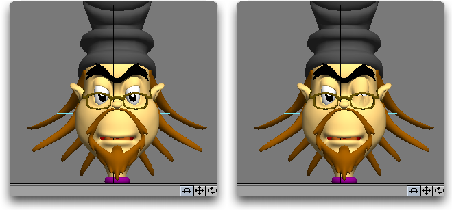
Overview: We begin by explaining what we are trying to do. The blinking of a character's eyes is modelled using four morphs: A left eye blink, a right eye blink, both eyes blinking and both eyes opening wide. We will control the left and right eye blinking by moving a null to the left and right respectively. The opening and closing of both eyes will be controlled by the same null, not with the left/right motion, but with the up/down motion of the null. We will call this null the "joystick" null. The big advantage of using this method is that if we move the null both sideways and up (or down) ie. diagonally, we will simultaneously combine all four morphs by using only one controller - the joystick null.
How do we achieve this with expressions? We will use four expressions:
- blinkLeft,
- blinkRight,
- blinkBoth and
- wideOpen.
Each expression will connect the joystick null to one of the four morph channels:
- object.Body.Eyes.Blink_Left,
- object.Body.Eyes.Blink_Right,
- object.Body.Eyes.Blink_Both and
- object.Body.Eyes.Wide_Both.
(The actual object in the screenshots is called William_Rig.) There remains one further hurdle: when the joystick null moves, it will move a certain distance (eg 50mm) which will need to be converted into a morph percentage. When using morphs, 100% is actually represented by the number 1 (and 0% by 0). Thus if we want a distance change of 50mm to correspond to a morph percentage change of 0% to 100% a function called "maprange" will convert this range of 0 to 1 for us.
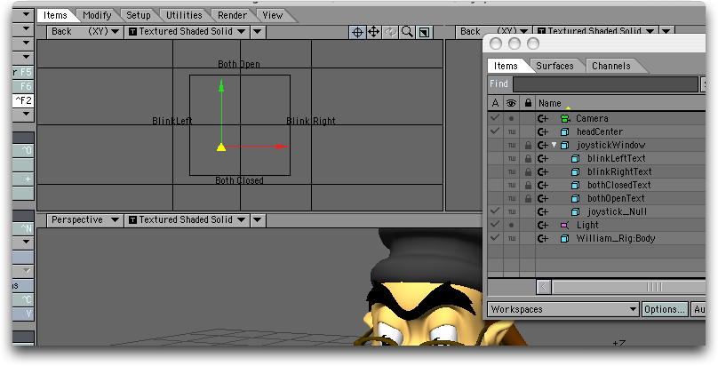
The joystick is just a null which we will move in the XY plane to control the morphs. The utility of the joystick approach is greatly enhanced if there is some graphic on-screen indicating which directions correspond to which morph changes, and also, where 0% position is. For this example we have created all of these using five other nulls. Four nulls are used with an "Item Shape" custom object whose only purpose is to place some text in the viewport. The last null has a square as the custom shape showing the range for the joystick (and the center). Also, all the nulls are parented to the "square window" null. This allows us to position the whole joystick control setup anywhere in the scene. For convenience, the joystick is usually placed in a viewport by itself (or alongside any other such controls).
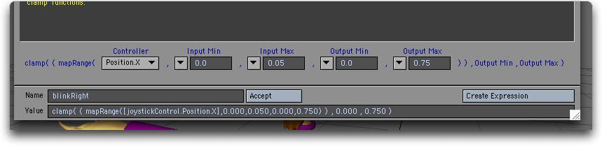
We will start by creating the BlinkLeft expression. This expression will control the closing of the left eye as the joystick moves from O to A (see the figure).
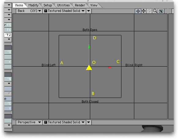
In terms of distance the null is moving from X=0 (at O) to X=-50mm (at A) the full range of the eye closing corresponds to a morph percentage change of 0 to 75% or, for the expression, a change from 0 to 0.75.
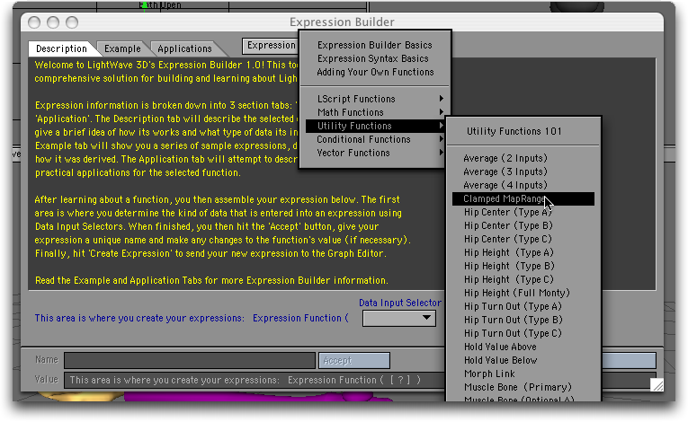
We will use Expression Builder (EB), so open the Graph Editor, click the Expression Tab and click the Builder button. Once the EB is open, use the pop-up menu to choose the Clamped Range utility function as shown:
We now have an expression template with five inputs.
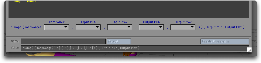
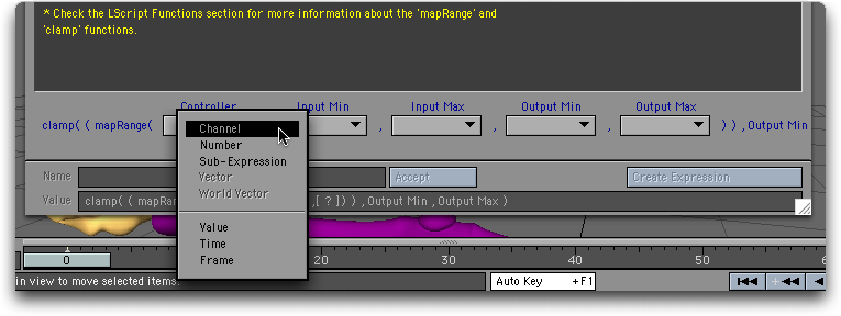
This is the function that "maps" the range of the joystick controller (ie. –50mm to 0mm) to the range of the morph (ie 0.75 to 0.0) To use it we need the joystick controller to go in the first input, so, select the "Channel" from the Controller input
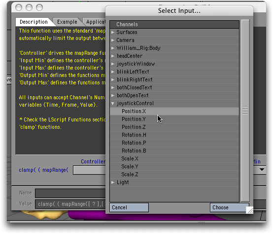
and then select the X position channel of the joystickControl object.
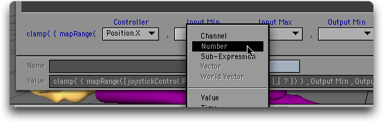
Now, the "Input Min" is the minimum value (as a number) that the joystick controller will take. In this case it is –50mm, or –0,05. Thus, choose the number option in the "Input Min" popup,
and enter –0.05. Similarly, for the remaining three entries: The "Input Max" is the maximum value we expect the X coordinate of the joystick to take (for controlling the left wink – it will actually move to +50mm for the right blink, but for the left wink we want an X value of 0 to correspond to the 0 morph percent. Thus the "Input Max" is 0. For the "Output Min" we want 0.75 – the morph percent that corresponds to –50mm (which isn't actually the smallest number), and for the "Output Max" we want 0 (giving a morph percent of 0%). Once all your numbers are entered, the template should look like this:
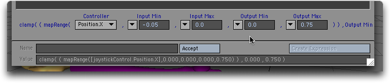
Now, click the Accept button, which tells EB to accept all your template entries. EB usually gives the expression some generic name; so delete it and type in "winkLeft" for the expression name.
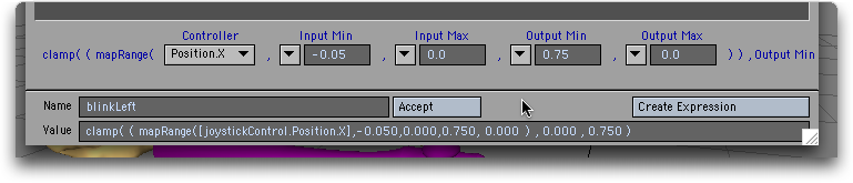
Finally, click the Create Expression button. This tells EB to send the expression to LightWave. If you now open the Graph Editor and click on the Expression Tab you should see your expression!
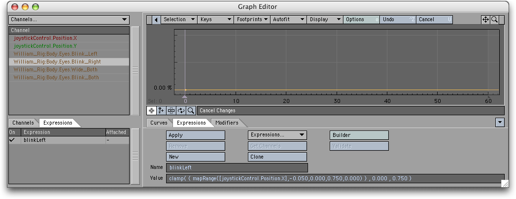
You can close the EB Panel as we won't need it until later. Back in the Graph Editor (GE), we now have to attach or apply the expression to the channel which it is going to control ie the left blink morph channel. To do this you need to get the channel into the channel bin (the list is on the top left of the GE). In our scene the morph channel is called William_Rig:Body.Eyes.Wink_Left". Once it is in the channel bin select it and then click the Apply button on the Expression Tab. A dot should appear next to the morph channels name telling you it now has an expression attached to it.
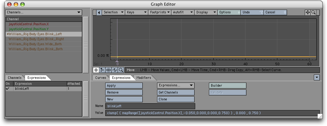
That's it for the left eye winking. If you move the joystick controller's X position from –50mm to 0 the left eye should wink.
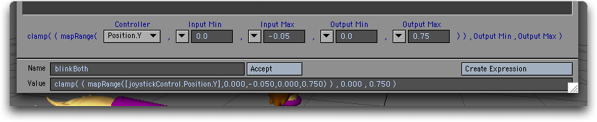
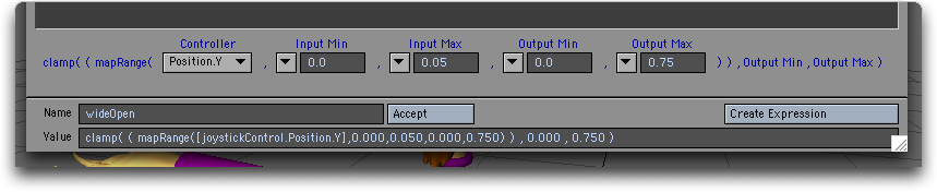
We now have to repeat this three more times to create the expression to control the right wink, the wide open case and the both closed case. The process is exactly the same except that the numbers entered into the Expression builder need to be changed and, for the blinkboth and wideOpen cases, it is the Y position of the controller that is used. These three EB Panels are shown below:
Wink right
Blink Both
Wide Open
Once you have applied these three expressions to their respective channels your joystick controller should be fully functional.
One last thing. Why is the "clamp" function part of each expression? The maprange function can take values outside the range of the "output" min and max values i.e. it can give negative morph percents or percents greater than 100%. But the clamp function stops this from happening. It takes in the values of the maprange function and forces them to stay within the range of the very last two numbers in each expression (in this case, the range 0 to 0.75)
Connecting LScripts to Expressions
You can write an Lscript function, or user defined function (UDF), using all the keywords available in LScript and then access the function in an expression.
Employing embedded LScript, users can now write their own functions to use with LightWave Expressions.
Expressions UDFs are used just like any built-in Expressions function. Parameter passing is limited to simple data types - strings, numbers and vectors. As long as an expression evaluates to one of these data types, it can be used as an argument. Expressions UDFs are stored in the LightWave->LScripts directory within their own directory called "expressions". A default library of functions can be maintained within this directory called "library.ls". This library of functions is automatically loaded into the Expressions engine when LightWave is initialised, and its defined functions are consequently available to any LightWave expression or Expressions UDFs that references them.
Additionally, individual Expressions UDFs can be stored in their own files in this same directory. The name of the file containing the UDF must exactly match that of the function name being referenced. The file may contain any number of other UDFs to support the main function, but must contain at least a UDF whose name and argument count matches that being referenced in the expression.
Data exchange between UDFs is not limited in their types. UDF-to-UDF calling is exactly the same as it is in LScript.
By way of example, assume the following files exist in the required directory:
\LightWave\support\plugins\scripts\LScript\expressions->library.ls
\LightWave\support\plugins\scripts\expressions->channelValue.ls
The "library.ls" file contains the following content:
locateChannel: fullchannel
    {
        parts = parse(".",fullchannel);
        group = ChannelGroup(parts[1]); // start with root channel group
        lastgroup = group;
        subgroup = nil;
        x = 2;
        while(group)
        {
            // scan sub-groups to match parts[x]
            // if a match can't be found, then it
            // is probably the start of the channel
            // name
            subgroup = ChannelGroup(group,subgroup);
            last if !subgroup;
            if(subgroup.name == parts[x])
            {
                group = subgroup;
                lastgroup = group;
                subgroup = nil;
                ++x;
            }
        }
        if(!lastgroup) return(nil);
        // anything left in the parts[] array are the components
        // of the channel name itself. put them together for
        // channel searching
        channelname = "";  // avoid creating an array
        psize = parts.size();
        while(x <= psize)
        {
            channelname += parts[x];
            if(x < psize) channelname += ".";
            ++x;
            }
        // scan the defined channels in the final group to see
        // if we can match the channel name
        chchannel = lastgroup.firstChannel();
        while(chchannel)
        {
            last if chchannel.name == channelname;
            chchannel = lastgroup.nextChannel();
        }
    return(chchannel);
    }
    // replace the built-in clamp() function
    clamp: val, lower, upper
    {
        result = val;
        if(val < lower)
        result = lower;
        else if(val > upper)
        result = upper;
        return(result);
    }
While the "channelValue.ls" file contains the following content:
    chan;
    chanName;
    channelValue: channel, time
    {
        if(chanName != channel) chan = nil;
        if(!chan)
        {
            // cache the channel for speed
            chan = locateChannel(channel);
            if(!chan) return(0);
            chanName = channel;
        }
        return(chan.value(time));
    }
In Layout, you might then enter an expression like: clamp(channelValue("WashLight.Intensity",Time),0.0,1.0)
This will invoke the channelValue() UDF, which then invokes the locateChannel() UDF (defined in the default library file "library.ls") to resolve a string channel reference to an actual LScript Channel Object Agent. The channelValue() UDF returns the value of the specified Light Object's intensity value at the current time. This value is then passed to the (script) clamp() UDF (also defined in "library.ls") to keep it in a specified range.
Alternately, you could use the Graph Editor's direct channel reference syntax with the UDF call:
clamp([WashLight.Intensity,Time],0.0,1.0)
UDF references that have been loaded into the Expressions engine are automatically updated the next time they are evaluated when their respective files have been modified. For instance, if you have expressions referencing channelValue(), altering the last line of the function to read:
return(chan.value(time) + 1.0);
will instantly return new values the next time the expression is evaluated (e.g., on the next frame).
Object References
Objects are referenced by their name. The system does not currently support space characters (' ') in object names, so cloned objects (i.e., "Null (1)", "Null (2)", etc.) cannot be used unless they are renamed.
The "Scene" object is the only pre-defined object in the system. All other object references must equate to an object in the current scene.?
Built-in Functions
All the built-in functions are described in the coding manual available with the SDK.
A vector is a group of related values. They could relate to position (X, Y, Z), rotation (H, P, B), color (R, G, B), etc. To get only one component, use a selector as demonstrated below.
Expressions react to interactively moved items, even if Auto Key is turned off.
You may use XS, YS, and ZS as aliases for Scale.X, Scale.Y, and Scale.Z.
Sample Expressions
HeadLight.rot(Time).h
returns the heading rotation value of the HeadLight item at the current time.
Left.pos(Time).x + Right.pos(Time).x
returns the sum of the Left and Right items' positions on the x axis.
<1,2,3>.y returns 2
<1,1,1>.rgb returns <255,255,255>
<.5,.25,1>.rgb returns <127,63,255>
BackLight.color(frame / Scene.fps).rgb
returns RGB vector value for color BackLight at a user-defined frame converted to a time index using the Scene object's fps setting. The frame variable is returned to the caller and can have its value explicitly set before each evaluation of the expression.
2 * "1 2 3".asVec.y returns 4
((Scene.usingLR ? (Scene.lr.right - Scene.lr.left) : Scene.width) / 2).asInt
finds the horizontal center of the frame.
Object References
Objects are referenced by their name. The system does not currently suport space characters (' ') in object names, so cloned objects (i.e., "Null (1)", "Null (2)", etc.) cannot be used unless they are renamed.
The "Scene" object is the only pre-defined object in the system. All other object references must equate to an object in the current scene.
Built-in Functions
| double | sqrt(double) | ||||||||||||
| double | exp(double) | ||||||||||||
| double | log(double) | ||||||||||||
| double | sin(double) | ||||||||||||
| double | cos(double) | ||||||||||||
| double | tan(double) | ||||||||||||
| double | asin(double) | ||||||||||||
| double | acos(double) | ||||||||||||
| double | atan(double) | ||||||||||||
| int | random(int,int) | ||||||||||||
| double | vmag(vector|double,double,double) | ||||||||||||
| (int|double|vector) | abs(int|double|vector) | ||||||||||||
| double | ceil(double|vector) | ||||||||||||
| double | floor(double) | ||||||||||||
| double | cosh(double) | ||||||||||||
| double | sinh(double) | ||||||||||||
| double | tanh(double) | ||||||||||||
| double | mod(double|vector,double|vector) | ||||||||||||
| double | pow(double,double) | ||||||||||||
| double | rad(double|vector) | ||||||||||||
| double | deg(double|vector) | ||||||||||||
| (double|int|vector) | max(double|int|vector,double|int|vector) | ||||||||||||
| (double|int|vector) | min(double|int|vector,double|int|vector) | ||||||||||||
| double range | (double,double,double) | ||||||||||||
| double | selector(double,double,double,double) | ||||||||||||
| double | step(double,double,double) | ||||||||||||
| double | round(double,int) | ||||||||||||
| double | frac(double) | ||||||||||||
| double | fac(double) | ||||||||||||
| double | cot(double) | ||||||||||||
| double | sec(double) | ||||||||||||
| double | csc(double) | ||||||||||||
| vector | cross3d(vector,vector) | ||||||||||||
| double | dot3d(vector,vector) | ||||||||||||
| double | cross2d(double,double,double,double) | ||||||||||||
| double | dot2d(double,double,double,double) | ||||||||||||
| vector | normalize(vector) | ||||||||||||
| vector | center(vector,vector) | ||||||||||||
| vector | extent(vector,vector) | ||||||||||||
| string | parse(string,string) | ||||||||||||
| double | number(string) | ||||||||||||
| vector | vector(string) | ||||||||||||
| string | string(double + int + string + vector) | ||||||||||||
| int | integer(double|string) | ||||||||||||
| string | strleft(string,int) | ||||||||||||
| string | strright(string,int) | ||||||||||||
| string | strsub(string,int,int) | ||||||||||||
| string | strupper(string) | ||||||||||||
| string | strlower(string) | ||||||||||||
| double | randu([double|int]) | ||||||||||||
| string | hex(int[,int[,int|"true"]]) | ||||||||||||
| string | octal(int[,int[,int|"true"]]) | ||||||||||||
| double | angle(vector,vector,int) | ||||||||||||
Common Object Methods and Data (all objects respond)
| vector | pos(double) | ||||||||
| vector | position(double) | ||||||||
| vector | rot(double) | ||||||||
| vector | rotation(double) | ||||||||
| vector | right(double) | ||||||||
| vector | up(double) | ||||||||
| vector | forward(double) | ||||||||
| vector | pivot(double) | ||||||||
| vector | wpos(double) | ||||||||
| vector | wposition(double) | ||||||||
| vector | wright(double) | ||||||||
| vector | wup(double) | ||||||||
| vector | wforward(double) | ||||||||
| vector | limits.pos.min | ||||||||
| vector | limits.pos.max | ||||||||
| vector | limits.position.min | ||||||||
| vector | limits.position.max | ||||||||
| vector | limits.rot.min | ||||||||
| vector | limits.rot.max | ||||||||
| vector | limits.rotation.min | ||||||||
| vector | limits.rotation.max | ||||||||
| vector | limits.right.min | ||||||||
| vector | limits.right.max | ||||||||
| vector | limits.up.min | ||||||||
| vector | limits.up.max | ||||||||
| vector | limits.forward.min | ||||||||
| vector | limits.forward.max | ||||||||
| vector | limits.pivot.min | ||||||||
| vector | limits.pivot.max | ||||||||
| vector | limits.wpos.min | ||||||||
| vector | limits.wpos.max | ||||||||
| vector | limits.wposition.min | ||||||||
| vector | limits.wposition.max | ||||||||
| vector | limits.wright.min | ||||||||
| vector | limits.wright.max | ||||||||
| vector | limits.wup.min | ||||||||
| vector | limits.wup.max | ||||||||
| vector | limits.wforward.min | ||||||||
| vector | limits.wforward.max | ||||||||
Mesh Object Methods and Data
| double | dissolve(double) | ||||||||
| int | points | ||||||||
| int | polygons | ||||||||
Light Object Methods and Data
| vector | color(double) | ||||||||
| int | points | ||||||||
| int | polygons | ||||||||
| double | coneangle.rad | ||||||||
| double | coneangle.radius | ||||||||
| double | coneangle.edge | ||||||||
Camera Object Methods and Data
| double | zoom(double) | ||||||||
| double | zoomfactor(double) | ||||||||
| double | focallength(double) | ||||||||
| double | focaldistance(double) | ||||||||
| double | fstop(double) | ||||||||
| double | blurlength(double) | ||||||||
| double | fovhor(double) | ||||||||
| double | fovhorizontal(double) | ||||||||
| double | fovver(double) | ||||||||
| double | fovvertical(double) | ||||||||
Scene Object Methods and Data
| int | points | ||||||||
| int | polygons | ||||||||
| int | renderstart | ||||||||
| int | renderend | ||||||||
| int | renderstep | ||||||||
| double | fps | ||||||||
| int | width | ||||||||
| int | renderwidth | ||||||||
| int | height | ||||||||
| int | renderheight | ||||||||
| double | aspect | ||||||||
| double | pixelaspect | ||||||||
| double | aspectratio | ||||||||
| int | minspp | ||||||||
| int | maxspp | ||||||||
| int | recursion | ||||||||
| int | maxrecurse | ||||||||
| int | recursedepth | ||||||||
| int | usingTraceShadows | ||||||||
| int | usingTraceReflection | ||||||||
| int | usingTraceRefraction | ||||||||
| int | usingFields | ||||||||
| int | usingEvenFields | ||||||||
| int | usingMotionBlur | ||||||||
| int | usingDOF | ||||||||
| int | usingLR | ||||||||
| int | usingLimitedRegion | ||||||||
| int | lr.x1 | ||||||||
| int | lr.left | ||||||||
| int | lr.x2 | ||||||||
| int | lr.right | ||||||||
| int | lr.y1 | ||||||||
| int | lr.top | ||||||||
| int | lr.y2 | ||||||||
| int | lr.bottom | ||||||||
| int | limitedregion.x1 | ||||||||
| int | limitedregion.left | ||||||||
| int | limitedregion.x2 | ||||||||
| int | limitedregion.right | ||||||||
| int | limitedregion.y1 | ||||||||
| int | limitedregion.top | ||||||||
| int | limitedregion.y2 | ||||||||
| int | limitedregion.bottom | ||||||||
Selector/Converter items
| double | x (selects the first element of a multiple-data type) | ||||||||
| double | y (selects the second element of a multiple-data type) | ||||||||
| double | z (selects the third element of a multiple-data type) | ||||||||
| int | r (selects the first element of a multiple-data type) | ||||||||
| int | g (selects the first element of a multiple-data type) | ||||||||
| int | b (selects the first element of a multiple-data type) | ||||||||
| vector | rbg (converts a vector data into color-normalized data) | ||||||||
| string | asStr (converts int,double,vector to string) | ||||||||
| string | asString | ||||||||
| int | asInt (converts string,double to integer) | ||||||||
| int | asInteger | ||||||||
| double | asNum (converts string,int to double) | ||||||||
| double | asNumber | ||||||||
| vector | asVec (converts int,double,string to vector) | ||||||||
| vector | asVector | ||||||||
A vector is a group of related values. They could relate to position (x,y,z), rotation (h,p,b), color (r,g,b), etc. To get only one component, use a selector as demonstrated below.
Expressions react to interactively moved items, even if Auto Key is turned off.
You may use XS, YS, and ZS as aliases for Scale.X, Scale.Y, and Scale.Z.