Hard Body Dynamics
Hard Body Dynamics (also called Rigid Body Dynamics or Geostatic Simulation) are used to set the physical interactions and characteristics of bodies that are solid, or fixed in shape. Some examples:
- Bowling Pins
- Windowpane breaking
- Objects exploding into pieces
- Dominoes
- Pinball machine
HardFX will easily create rigid body characteristics and behavior when applied to a goal object in a scene. You then need to set the Weight, Reflection, and Collision settings and calculate. The object that has an impact will rotate and move according to its shape and size. It will automatically calculate the result so that the outcome will be more realistic.
You do not have to create individual objects for the pieces that break into parts for calculation. If the points are connected as a continuous surface, or if it is a group, it will be determined as parts. Also, it is possible to create the events as a trigger.
One of the big features is the Edit tool which allows you to adjust the path of the objects by simply dragging the mouse, and to move, rotate, and smooth the motion itself. With this addition, you do not have to calculate every time you make some changes. As a result, you can easily create the movement that you wish.
HardFX is located in the Dynamics Tab of the Object Properties Panel. Choose Hard from the Add Dynamic drop down list and then click on HardFX in the list to open up the HardFX options.
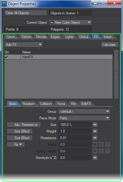
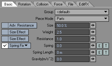
Basic Tab
You can set the basic settings like air resistance, weight, and size.
- Group - you can group Dynamic objects with a user-defined name to prevent unwanted interaction. This also works with ParticleFX controllers. This becomes very handy when you are working on a complex scene and you want certain Wind emitters to only affect certain objects.
<default> Includes all groups.<new group> Creates an individual group and can associate functions within a group.
You can associate with ParticleFX’s functions using group function. If it is in the same group, you can associate settings. Also, just by removing from the group, you can break the association.
- Piece Mode - Setting for how HardFX will treat the object.
- 1piece - Make all polygons as one piece.
- Parts - Make polygons that have common points as one piece.
- 1piece>parts (collision) - When it starts, it will be in 1 piece mode, but with Collision, it will change to parts mode.
- 1piece>parts (event) - When it starts, it will be in 1 piece mode, but with a Collision event, it will change to parts mode.
The event’s detection is made by each part’s pivot.
- Adv. Resistance - Changes the calculation of the air resistance to an Advanced Mode. Usually, the value for air resistance is set only in Resistance; however, by turning Adv. Resistance on, it will include the object’s XYZ ratio. This helps create realistic physical movement like leaves falling.
If the value for the resistance is 0 or the ratio of each part is the same, even if you turn on Adv. resistance, you will not get any effect. In the case of a sphere (with same radius), since XYZ ratio are the same, you will not get any effect.
- Size - used to set the size of the object that will be used for collision. The size will be the percentage of each part.
- Size Effect (weight) - Proportionate to each part’s weight to size. By turning it on, you can set weight proportional to the size (scale).
- Weight - Sets the mass for each part. A higher value will increase the velocity from the items origin, while a lower value slows the velocity.
- Size Effect (Resistance) - Controls the relationship of each part’s resistance to size. By turning it on, you set resistance proportional to size (scale).
If the value for the resistance is 0 or the ratio of each part is the same, even if you turn on Size Effect (resistance), you will not get any effect.
- Resistance - This one is not a characteristic of the object or part itself, even though it can be set per object, per group or per part. Resistance controls the amount of resistance of the environmental medium in which the simulation is taking place. For example, this affects how quickly an object or part moves through the virtual air in the scene. The default is 1.0; raising this number increases the resistance to the item’s movement and lowering to a number between 1.0 and 0.0 decreases the resistance. This allows the simulation of a wide range of gaseous or even liquid media as the environment for the physical simulation. To simulate behavior within a normal atmosphere at sea level, a value of .14 would be appropriate. A value of 1.0 gives the medium a character close to that of molasses. This can be used as a way to differentiate the behavior of differing parts or objects within a given scene.
If you are coming to LightWave from Maya, the function that is most similar from that application is “Damping.”
Fix
Sets a Fix each part’s pivot.
- Free - Will not fix.
- Spring Fix - Fixes with a spring, causing a back and forth motion.
- Fix - Fixes.
- Spring - When Spring Fix is selected, this represents the power of the Spring, which acts like a rubber band.
- Spring Length - Setting for length when spring power is 0. Spring length is the length of the spring and with the length of spring offset of the pivot, it moves freely. Depending on the value of spring, spring length will vary.
- Gravity - Setting for downward (-y) gravity.
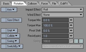
Rotation Tab
The Rotation Tab will set the parameters for rotation.
- Axis -Restricts rotation along the specified axis.
- Free - Not restricted
- x axis - Allows rotation only along the X axis.
- y axis - Allows rotation only along the Y axis.
- z axis - Allows rotation only along the Z axis.
- xz axis - Allows rotation only along the X and Z axis.
- xy axis - Allows rotation only along the X and Y axis.
- yz axis - Allows rotation only along the Y and Z axis.
- Impact Effect - Settings for the effect on rotation when there is an impact.
- Roll - Creates rotation depending on the size and velocity.
- Force - Creates rotation depending on the impact. This is useful for regular physical movement.
- None - No effect to the rotation.
- Stop - Stops the rotation.
If the Impact effect mode is roll, you cannot assign Y axis rotation to the Axis. Roll refers only to X and Z rotation.
- Wind Effect - Setting for rotation from the effect of Wind.
- None - Does not effect the rotation.
- Accelerate - Strengthens the current rotation.
- Roll - Creates perpendicular rotation to wind and moving direction.
- Spin - The object will rotate around the axis that it is moving along..
- Size Effect (torque) - Makes a ratio to each part’s torque to size. By turning it on, you can set torque proportional to the size.
- Torque Min - Sets the minimum value for force for the rotational direction. By combining it with torque Max and giving a different torque to each part, you obtain a different rotation for each part.
- Torque Max - Sets the maximum value for force for the rotational direction. By combining it with torque Min and giving a different torque to each part, you obtain a different rotation for each part.
- Shift - Sets the direction of the pivot shift.
- Random - Moves the pivot point in a random direction.
- x shift - Moves the pivot point in the X direction.
- y shift - Moves the pivot point in the Y direction.
- z shift - Moves the pivot point in the Z direction.
- object pivot - Sets the part’s pivot as the object’s pivot.
- Pivot Shift - Moves the pivot of the rotation towards the direction set in shift. The amount is the percentage of the part’s size.
- Collide - Restricts the movement of Resist (spin).
- Free - Resist (spin) will always be on.
- Collide - Resist (spin) will turn on only when a collision occurs.
- Collide (axis) - Resist (spin) will turn on only when collision occurs and the axis is perpendicular to the collision surface.
- Resist (spin) - Applies resistance to the rotational direction. This is useful when speed decreases by friction.
- Swing - Fixes each part’s position. Useful when you want to create a jiggly movement.
- Free - Will not fix the position.
- Swing - Turns on swing for fixing the position.
- Swing (wind) - Turns on swing and also adds wind to the jiggle.When you have roll or spin selected in wind effect, the effect of the wind will be invalidated.
- Spring - Sets the restoring force when swing is on.
The value for spring power is for each rotational direction.
- Switch By - Changes the setting by the specified trigger.
- Changed group - When the group is changed in Collision, settings will change.
- Event - When an event is given by Collision, settings will change.
- New Impact Effect - Changes the mode of impact effect when the trigger set in “switch by” is given.
Supplement: By default, HardFX sets the axis of the calculated parts to the object’s pivot, unless it is changed by Shift or Pivot Shift.
Set Shift to Object Pivot to make the object’s pivot point the center of the axis,.
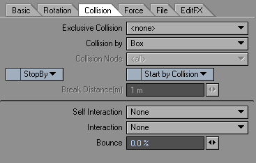
Collision Tab
Settings for collision.
- Exclusive Collisio n- Selecting an item from this list will exclude all other collision objects from the calculation.
- Collision By - Sets the detection method for collision.
- Node - Detects the object’s vertex.
- Box - Detects with a box vertex including the object.
- Sphere - Detects the sphere set, in size, in Basic Tab.
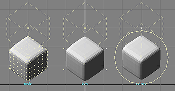
From let to right: node, box, and sphere
- Collision Node - When Collision By is set to Node, you can select the vertex of collision detection by using Vertex Maps.
- Stop By Event - With Collision: Event , the movement will stop. It will move again with startByCollision or RestartByCollision . Event is determined by each part’s pivot.
- StopByStabilizer - will attempt to stop a dynamic object from continually oscillating if the calculation reaches a set amount.
- Start By Collision
- Start By Collision -Usually, an animation starts from the start of the calculation, but when you select StartByCollision, the animation is made after the collision is determined.
- Restart By Collision - The animation is made after the collision is determined. The difference with StartByCollision is that even if there is no collision, the animation is still created.
StartByCollision is valid only with Collision. It will not work with two HardFX.
- Break Distance - Sets the condition for Start By Collision’s collision factor. The calculation will not start if the distance is shorter than the specified distance.
- Self Interaction - Sets the interaction within the same object.
- None - No calculations made for interaction.
- Sphere - Detects the sphere set, in size, in Basic Tab.
- Box - Detects with a box vertex including the object.
- Interaction - Sets the interaction between objects.
- None - No calculations made for interaction.
- Sphere - Detects the sphere set, in size, in Basic Tab.
- Box - Detects with a box vertex including the object.
- Bounce - Sets the power of the interaction. When the relative speed is kept at 100% after collision, the energy of the collision is not lost.
Force Tab
Applies settings for amount and behavior for the types of force that will be applied.
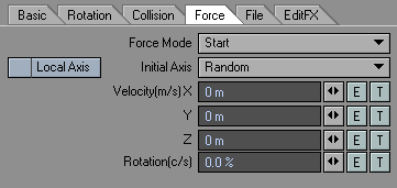
- Force Mode -Sets the type of force that will occur.
- Start - Force will occur at the beginning or when started by StartByCollision.
- break(1piece>parts) - In Piece mode, when you select 1piece>parts, force will occur when it starts to break.
- Event - Force will occur from FX_Collision’s event mode. The detection will be each parts’ pivot.
- Initial Axis - Set the axis of the rotational power.
- Random - Sets the axis to a random direction.
- x - Sets axis to X direction.
- y - Sets axis to Y direction.
- z - Sets axis to Z direction.
- Local Axis - When activated, specification for Velocity(m/s) is set to the object’s local axis.
- Velocity(m/s) - Sets the velocity of the force along the specified axis.
- Rotation (c/s) - Sets the rotational power by rotational speed (cycles/sec).
File Tab
Manages copy, paste, and HardFX’s motion data.
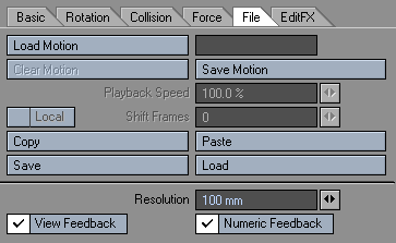
- Load Motion - Loads a previously generated motion file.
- Clear Motion - Clears a loaded Motion file.
- Save Motion - Saves the generated motion to a file, which will be used subsequently to deform the object.
- Playback Speed - This will set the percentage of the playback speed of HardFX data about to be played.
- Shift Frames - Shifts the playback starting frame of HardFX data. By default, the number entered is regarded as a number of seconds to shift the motion of the .mdd file. If you prefer to use frames, enter the number of frames followed by the letter “f”; “-400f”, for example, to shift so that the motion in the .mdd file starts at frame -400.
- Local - Plays back based on the local translations (move, rotate and scale) of the object. Allows an .mdd deformation on an object while respecting new motion applied to that object.
- Copy - Copies the current settings between dynamic objects.
- Paste - Pastes the current settings between dynamic objects
- Save - Saves all the settings contained in the HardFX properties.
- Load - Loads a saved settings file. Similar to using a Preset.
- Resolution - Sets the accuracy of calculation by how big the maximum error is. When it approaches 0 the accuracy increases and errors will decrease, but the amount of calculation will also increase, resulting in longer processing times.
- View Feedback - Sets the feedback in Layout when controlling HardFX. When the display is poor or the display speed is slow, uncheck this.
- Numeric Feedback - Sets the numerical feedback in Layout when controlling HardFX. When the display is poor or the display speed is slow, uncheck this.
EditFX Tab
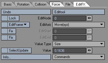
- Edit Tool - Activates the ability to edit Nodes. To edit, you will have to calculate HardFX, or load HardFX data.
- Undo - The Edit tool has its own undo. Click this button to undo the last edit. You can only undo one edit.
- Edit Node - Specify the number of the parts to be edited. If the Edit tool is activated, you can select from the Layout by clicking the parts.
- Lock - Displays whether the parts specified by editNode are in Lock state or not. When parameters like size is changed by Value, it will be in Lock state. In this state, even if the size parameter is changed from the original, the Locked parameter will not change. To activate the size parameter, uncheck the Lock.
- Edit Frame - Specify the frame(s) to be edited.
- All - All frames will be editable.
- After - Can edit frames before the count.
- Before - Can edit after the count.
- Current - Can edit only the current frame.
- Edit Axis - Specify the direction to edit.
- move(xyz) - Move the selected parts.
- move(x) - Move the selected parts to X direction.
- move(y) - Move the selected parts to Y direction.
- move(z) - Move the selected parts to Z direction.
- rotation(x) - Rotate the selected parts to X axis.
- rotation(y) - Rotate the selected parts to Y axis.
- rotation(z) - Rotate the selected parts to Z axis.
- bend(x) - Rotate to X axis by making the center as the location data and rotation data from the selected parts.
- bend(y) - Rotate to Y axis by making the center as the location data and rotation data from the selected parts.
- bend(z) - Rotate to Z axis by making the center as the location data and rotation data from the selected parts.
- Fix Edit Start - Activates EditStart. When activated, the current frame value is inputted in EditStart. When this is not specified, all the frames before the current frame will be edited. When you specify fix, you can get a smooth edit effect with EditStart’s frame, but when you press Ctrl key while dragging, you will get a linear edit effect.
- Edit Start - Fixes the specified frame value and you can get a smooth edit effect between the current frames.
- Fix Edit End - Activates EditEnd. When activated, current frame value is entered in EditEnd. When this is not specified, all the frames after the current frame will be edited. When you specify fix, you can get a smooth edit effect with EditEnd’s frame, but when you press Ctrl key while dragging, you will get a linear edit effect.
- Edit End - It will fix the specified frame value and you can get a smooth edit effect between the current frames.
- Value Type - Select the parts data to edit using value.
- Size - Changes the size parameter for the parts selected in editNode.
- Weight - Changes the weight parameter for the parts selected in editNode.
- Resistance - Changes the resistance parameter for the parts selected in editNode.
- Torque - Changes the torque parameter for the parts selected in editNode.
- pivot(x) - Changes the pivot’s X axis for the parts selected in editNode.
- pivot(y) - Changes the pivot’s Y axis for the parts selected in editNode.
- pivot(z) - Changes the pivot’s Z axis for the parts selected in editNode.
- Value - Sets the value for selected item in Value type. When edited, Lock will be checked. In this state, even if the original parameter is changed, the Locked parameter will not change. To activate the size parameter, uncheck the Lock.
- Selected Update - When activated, you can re-calculate only the parts selected by editNode. To re-calculate, activate Calculate with SelectUpdate checked. You do not have to re-calculate when you move the path or key frame data with editAxis
Command
- Smooth -Referencing the current frame, the movement of the parts that was selected by editNode will be smooth. When editStart and editEnd are not specified, the current position will be copied to all the frames. When editStart and editEnd are specified, it will make the position information smooth from the specified frame to the current frame.
- Make Path - This command will create a Null object whose path is identical to the motion path of the selected part.