Texture Editor
Introduction
While you can vary a parameter over time with an envelope, the parameter is not dynamic over the surface: the value for a particular frame is the value for the entire surface. Textures, on the other hand, essentially let you vary the value dynamically over the surface (as well as in time). A Color texture is probably the easiest illustration. Instead of using the same color on a surface, you can map a picture (a color texture image map) onto the surface that lets the color differ over the surface area.
You can use Image Maps for more than just color. On other surface parameters, the color element is ignored and only the brightness of each pixel varies the value over the surface. For example, you can use an Image Map with Specularity to suggest scratches on a surface. Textures let you divide a surface into thousands of smaller areas and apply a different level of the surface attribute to each individual area.
In addition to Image Map textures, you can also use Procedural Textures and Gradients. Procedurals are mathematically computed images. Gradients act as a type of envelope, except that the value can change over a condition other than time. Select these options by using the Layer Type pop-up menu.
Texture Layers
LightWave can layer surfaces infinitely; once you set the original texture, you can add another layer by using the Add Layer pop-up menu. You can choose to add any of the layer types - the type can be changed later if necessary.
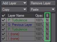
The layer list window shows you all of the layers. The first column indicates whether the layer is active (checked) or not (blank). You can toggle the status by clicking in the column. The next column shows the layer name, which indicates the type of layer. Next is the opacity percentage, followed by the Blending Mode (e.g., + for Additive).
You can choose which layer to work on by simply clicking on it in the window. To remove a layer, select it and then click Remove Layer.
Copy and Paste
You can copy the currently selected layer or all of the layers in the Surface list to a memory buffer by using the Copy pop-up menu. For the Paste operations, Replace Current Layer will replace the selected layer with the buffer contents, even if the buffer contains more than one layer. Replace all Layers will clear all existing layers and then add the buffer contents. Add to Layers simply appends the buffer contents to the end of the list.
The buffer contents will remain until you quit LightWave.
Layer Order
Texture layers are always listed in order from top to bottom. New layers are added on top of existing layers. Keep this in mind when you set up multiple layers. For example, if you want an Image Map with fractal noise across the entire surface including the image, you must map the image first and add the fractal noise afterwards. Of course, you can reorder layers by dragging them with your mouse.
The base Surface settings - those set on the Surface Editor’s Basic Tab - always sit beneath all layers.
Blending Layers
To set the opacity of a texture, use the Layer Opacity field. Reducing the value from 100% makes the overall texture more and more transparent. Setting it above 100% can force a texture layer to unnatural values.
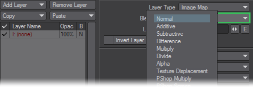
The Blending Mode determines how the layer is blended with other layers. With Normal, underlying layers will be totally covered (i.e., replaced) by the texture, assuming Layer Opacity is 100%. The texture acts like an alpha matte; thinner areas of the texture allow the underlying layers to show through. If Layer Opacity is 50%, you get 50% of the layer and 50% of the underlying layers. Additive, adds the texture (times the Layer Opacity) to underlying layers.
To achieve an even blend between multiple texture layers, use Normal. Then divide the number of the layers into 100% and use the resulting value as your Texture Opacity value. For example, the first (bottom-most) layer would be set to 100% (100/1), the second layer will be set to 50% (100/2), the third layer will be set to 33% (100/3) and the fourth layer will be set to 25% (100/4). Subtractive subtracts the layer from the underlying layers. Difference is similar to Subtractive but takes the absolute value of the difference. Multiply factors the layer by the underlying layers. Multiplying by darker colors will darken the image, while brighter colors will brighten. Divide multiplies the underlying layers by inverse of the layer. This generally has the opposite effect of Multiply.
The Alpha Blending Mode makes the layer an alpha channel on the preceding layer. In other words, it cuts out parts of the preceding layer and makes those areas transparent. White in the alpha image creates opaque areas and black creates transparent areas. Shades in between will do a little of both. If the image, procedural, or gradient has color, the alpha image is based on the brightness of the areas.
Each layer’s Blending Mode is indicated in the right-most column of the layer list.
Texture Displacement displaces (distorts) layers above it, similar in effect to a Bump Map.
PShop Filters
Photoshop-style filters have been added to the Blending Mode menu in the Texture Editor. They are designed to work like the blending modes found in Photoshop. While the names may be similar in some instances, such as LightWave’s native Multiply and the Pshop Multiply mode, the Photoshop modes are mathematically different from the native LightWave blending options, and therefore produce different results.
- PShop Multiply - Blends the base color with the blend color, making the image darker by multiplying the color values together. A black color will make the final blend black. A pure white color will change nothing. Working with colors other than black or white will produce a darker color.
- PShop Screen - The opposite of PShop Multiply, the color values are inverted, multiplied together, then inverted again. A black value will change nothing, while a white color will produce a white result.
- PShop Overlay - A combination of PShop Multiply and PShop Screen, the formula is dependent on the base color. A lighter base color will produce a lighter result, while a darker base will result in a darker color.
- PShop Softlight - Similar to PShop Overlay, except the blend color is the determining factor. A lighter blend color will produce a lighter result and a darker blend color will produce a darker color. Colors are mixed, so a pure white or pure black blend color does not produce a result of pure white or pure black.
- PShop Hardlight - The opposite of PShop Overlay (not PShop Softlight!) and is dependent on the blend color. Multiplies the blend and base colors, with a lighter blend color resulting in a lighter result and dark blends producing darker results.
- PShop Colordodge - The base color is brightened to reflect the blend color by reducing the contrast. A blend color of black changes nothing.
- PShop Darken - The base and blend colors are compared and the darker color is the one used.
- PShop Lighten - The base and blend colors are compared and the lighter color is selected.
- PShop Exclusion - Subtracts the blend color from the base color, or base from blend, whichever has the brighter color value. A pure white blend value will invert the base color value.
Image Properties
After you select one of the Projection settings, use the Image pop-up menu to select or load an image/sequence. Clicking the Edit Image button launches the Image Editor Panel. Here you can adjust certain aspects of the image(s).
The available Image settings on the Texture Editor Panel vary depending on the Projection setting. Two settings always appear, however. Pixel Blending smooths out the pixelation that can occur when a camera gets close to the mapped surface.
MipMap
Mip-mapping is used in LightWave and today’s games to avoid texture graininess at a distance or at a low angle. Basically, lower-res versions of the texture are generated in real time to save time processing the original image to map onto a polygon. Please note that due to the nature of this filtering method, low-res textures may appear somewhat blurry. Mip-mapping is very useful in animation projects because it ensures that the same image is used no matter where the image-bearing object is in the scene, however, the total memory cost for mip-mapping tends to average out at 1.5 times the image size in memory. On still renders, you can turn off mip-mapping to save memory.
The antialiasing Strength value determines the amount of antialiasing. The default setting of 1 should be used in most cases; however, the level may need to be raised or lowered slightly to better match the particular image. This value can be set to higher levels to add blurring effects to the image.
Tiling
Planar, Cubic, and Cylindrical Image Map projection have Tiling (i.e., repeating) options, which you can set independently for the horizontal and vertical repeating directions.
Image used for the following examples
Reset
Reset is the no-repeat mode. The underlying surface will be visible if the image is smaller than the surface area.
Repeat
Repeat tiles the image until it fills the surface.
Mirror
Mirror tiles the image, but flips the image horizontally or vertically.
Edge Edge extends the edges of the image to cover the surface. This setting works best when the outer edges are a solid color.
The repeating options are relevant only if the Scale, Position, and Rotation settings (at the bottom) are set in such a way that the image will not fill the surface area.
Cylindrical and Spherical have Wrapping options that set how many times the image appears horizontally, Width Wrap Amount, and vertically, Height Wrap Amount (not applicable to Cylindrical). This sets how many times you want the image wrapped for the given Scale values. Generally, you’ll want this set at 1.
Wrap amounts can be negative, which will reverse the image as it is wrapped around in the opposite direction.
Texture Placement
Once you set the image properties, you must now scale and position the image. Textures are initially positioned referenced to the X, Y, or Z Texture Axis. For Planar projection, think of the axis as a nail used to hold a photograph to a wall. For Cylindrical, think of the axis as the cardboard center of a roll of paper towels. Spherical is very similar. However, you cannot select an axis for a Cubic map.
For example, a soda can would use a Y Texture Axis because it sits vertically. The fuselage of an airplane, on the other hand, would probably use the Z Texture Axis.
You should generally model objects so that they face the positive Z axis.
If the Texture Axis is perpendicular to a surface (such as the sides of a box using the same surface name as the projected side, the image will run through the surface.
Surface Size, Position, and Rotation
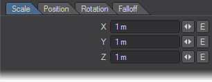
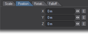
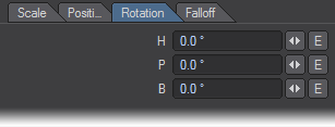
Scale defines the size of the surface to which the texture is applied. Position defines the coordinates of the center of the texture on the surface. Rotation defines how much the texture rotates around the center Position.
Different combinations of Texture Axis and Rotation can achieve the same results.
Generally, you want to match these settings with the actual surface. Automatic Sizing causes LightWave to calculate the Scale and Position of a selected surface and input those values. It computes an imaginary bounding box around all areas using the current surface. This will fit an Image Map perfectly onto the surface.
Use Automatic Sizing for starting values when using procedural textures.
If the Scale is smaller than the surface size, an Image Map will tile across the surface (assuming that one of the Repeat options is active). You might also see the tiling effect if the Position is not set to the actual surface center.
Because LightWave’s textures are three-dimensional, there is no rule stating that the center of a texture must be located somewhere within the bounds of the surface. You can place the texture center outside of the surface and still get a texture to appear across the surface. Textures extend in all directions throughout the virtual space in Layout, but appear only on the surfaces that are set to display them.
There are definitely times where you don’t want the texture sized exactly to match the surface. Such is the case with Procedural Textures, which usually look better when the Scale is smaller than the Surface Size because it adds more detail. Another example is when you use only part of an image that is texture mapped.
Falloff
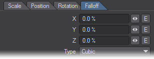
The Falloff values specify the apparent falloff for every unit of distance moving away from the texture center, defined by the Position settings. (The unit of distance is defined by the Default Unit setting on the General Options Tab of the Preferences Panel.) When you animate the Position with an envelope, the position at frame 0 is used as the center for falloff purposes.
The Type pop-up menu determines the shape of the Falloff. (In previous versions, the Falloff was always cubic.) Linear Falloff types (i.e., LinearX, LinearY, and LinearZ) operate only in one direction. If you use 100% LinearX, for example, the texture will fall off only in the positive X direction from the texture center. To fall off towards negative X, use -100%.
With Cubic, the Falloff occurs on both the positive and negative sides. You can achieve a linear-type falloff in both directions by using Cubic and setting the two axes you do not wish to fall off to 0%.
Using a Reference Object
Although you can explicitly set the Position, Size, and Rotation of a texture, you can also assign a Reference Object - normally a Null object - and get similar results. The Reference Object makes all of these settings operate relative to itself. You can better control the texture animation by animating the Reference Object. Moreover, you can use different Reference Objects for different Surface Textures (e.g., surface color, diffusion, specular, and so on).
An object’s pivot point does not affect surfacing.
Freezing Reference Object/Camera
If you set a Reference Object (or Reference Camera used with Front Projection Mapping) and then select (none) from the related pop-up menu, a dialog appears that asks, “Do you want to keep item’s parameters?”.
If you click Yes, you will store the reference item’s state at the current frame in the object. (Don’t forget to save it.)
World Coordinates
Normally, textures are locked to a surface and travel with it, as the object is moved, stretched, rotated, or deformed. Selecting World Coordinates will lock the texture to LightWave’s Origin instead of those of the surface. Moving the object now will result in the object traveling through the texture. All Texture settings continue to be valid, but now are relevant to the World Coordinates.
World Coordinates can create the look of light beams moving through a fog. You create this effect by using transparent light beams with a fractal noise texture for Color and/or Luminosity activated. As the light beam is moved about, it will move through the fog created by the fractal noise. Using World Coordinates on a Transparency Map with Falloff can make a spaceship cloak (turn invisible).


