Surface Editor
Introduction
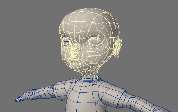
Except for new Primitive objects, LightWave objects are composed of one or more polygons. What each polygon looks like is defined by its surface attributes or usually just surface for short. Groups of polygons can share the same surface, and the polygons need not be contiguous. The polygons can even be in different objects.
Surfacing Objects
Let’s take a simple cube. It has six sides and, therefore, at least six polygons. Each side could have its own individual surface; all six sides could use the same surface or any combination in between.
The polygons that make up a surface are given a name, usually in Modeler. The surfacing information associated with the surface name is stored in the object file. When an object is later loaded, the surfaces used in it are also loaded, including any image files referenced in the surface attributes.
WARNING: Surface settings are saved as part of the associated object file(s), not in the Scene file, with the exception of primitive objects. To save Surface settings, save the object.
Assigning Surface Names
- In Modeler, select the polygons that you would like to surface
When you rename all of the polygons that already have a surface name, use the Statistics Panel (open/close with the Statistics button at the bottom of the interface - or press W) to select them. Also, if you are naming all polygons, you don’t need to select any.
Choose Surface (located at the bottom of the interface, or press Q) to open the Change Surface dialog.
Enter the surface name for the selected polygons and click OK. You can also select an existing surface name from the pop-up menu.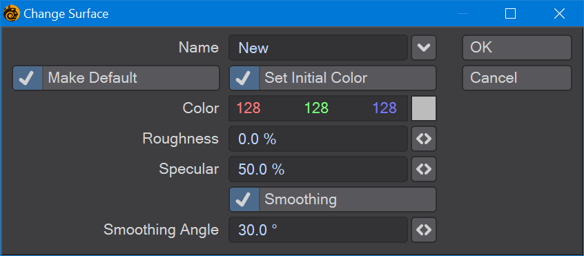
You should strive to give your surfaces meaningful names. For example, say you had a car object. One surface might be called “chrome,” which you apply to the bumper, door handles, antenna, etc. “BlackRubber” might be another surface, which you apply to the tires, rubber gaskets, etc. You might use “RedMetal” for all of the exterior painted metal parts of the car.
To set some basic Surface settings, activate Set Initial Color, and adjust the available settings as desired. You can perform more advanced surface editing using the Surface Editor.
The Make Default option automatically updates the Surface option on Modeler’s General Options Panel ( Edit > General Options ). This controls the default surface name used when you create new geometry.
Click OK to confirm.
Think about your surface names. With the car example above, you may want to name the area of the car to have more granularity and better surface sorting. For instance, you could name the surfaces for the wheels as "wheels.tire", "wheels.rim", "wheels.caliper" and so on. That way, all your wheel surfaces will be gathered together.
Surfacing Ideas
By no means should you restrict yourself to using, say, a procedural texture for what its name implies. The unlimited combination of settings, layers, nodes, and different surface attributes yields an infinite number of visual possibilities.
You are encouraged to load and render the various objects that come with LightWave. Study their surfacing techniques. Change them if you want. However, do not fall into the trap of thinking the surfaces are perfect. Many of them are far from it. Surfacing is an art form, and 3D artists each have their own opinions on the best approaches. You need to develop your own.
Surface Editor Panel

The Surface Editor Panel will list the characteristics of your named surfaces; you can access this panel from both the Layout and Modeler modules. There are four buttons at the top of this list:
- File... - A dropdown menu to load and save individual surfaces or libraries of surfaces
Preview - this button opens the selected surface in a Surface Preview window
Note that the Preview button does not work in Modeler since there is no VPR
- Preset... - A dropdown menu to save surfaces to the preset window
- Edit Node Graph - Opens the Node Editor. You can also double-click on a surface name in the Surface Editor to open the Node Editor
- Search - Searches the surface names. The search can be made case sensitive or cleared using the dropdown
Surface Search
Searching in the Surface Editor is based on the following string:
ObjectName/SurfaceName@MaterialName#ShadingModelName
This means that you can search for objects and get their surfaces, or search for surfaces or materials or even shading methods by preceding them with:
- / - for surface names
- @ - for materials
- # - for Shading models
Regex example 1

To get more control over your searches, you can use Regular Expressions. The last search in the example above reads:
re:mar.+/.+lor
which translates to
RegEx: find all objects starting with "mar" with surfaces starting with anything but having "lor" in them
resulting in only the Marble-GlassTwist object being found with the GlassColor1-4 surfaces.
Regex Example 2
In the same scene, we want to only select surfaces on objects that have swirl in their object name, but just surfaces ending in the letter s. We can do this thanks to regex with re:+swirl.+/.+s@.

I was going to write swirl but decided just to put the wildcard in again.
The Surface Editor regex style is taken from QT. More information and syntax can be found here.
New Panel Hierarchies
New panels (like the Surface Editor, Render Properties, Scene Editor, Scene/Dope Editor and others) have collapsible hierarchies. Holding down the Ctrl key when clicking the expander arrow will open or close all children, holding down Shift will affect all siblings and holding down the Alt key when clicking a closed hierarchy will open that group and shut others. Holding Alt when there are several hierarchies open will maintain the one clicked on and close the others. All of the modifiers can be combined, they are not mutually exclusive.
Surface List
The list on the left has the surfaces available for edit and gives the material used. It is divided into groups by object. Surfaces that have no object can appear here but will be removed when the scene is cleared.
Double-clicking on a Surface name will open the Node Editor
Right-clicking on a surface name will bring up several options:
- Copy - Copies the selected surface or surfaces
- Paste - Pastes copied surfaces. It will paste the same surface over all selected surfaces
- Paste Common - Pastes attributes under the Material: Clip Map, Smoothing, Smoothing Threshold, Vertex Normal Map, Double Sided, Opaque
- Paste Shading Model - Pastes only the shading model used for the copied surface
- Paste Node Graph - Pastes only the node graph used for the copied surface
- Rename - Renames the selected surface. Selecting multiple surfaces will result in a Rename requester for each surface. Hitting Cancel in any of the Rename requesters will cancel any further renames in the selection.
- Select by Same - Brings up choices for selecting similar surfaces
- Name - If there are surfaces with the same name they will be chosen (good for getting rid of duplicates with imported assets)
- Material - Surfaces using the same material will be selected
- Shading Model - Surfaces using the same Shading Model will be selected
- Material/Shading Model - Surfaces matching Material and Shading Model
- Name/Material/Shading Model - Surfaces matching Name, Material and Shading Model
- Load - A submenu of loading choices
- Load Surface - Loads a saved surface
- Load Library by Index - Loads a surface library assigning surfaces by object index
- Load Library by Name - Loads a surface library assigning surfaces by object name
- Load Library by Name, Append Extra Surfaces - Loads a surface library assigning surfaces by object name and also loads surfaces that are contained in the library for which there are no scene objects
- Save - A submenu of saving choices
- Save Surface - Saves an .srf file referencing a single surface
- Save Library - Saves a .lib file referencing all the surfaces for an object or objects. Libraries are named the same as the object that hosts the surfaces saved
- Convert - Offers two choices:
- Layered to Standard Nodes - Converts surfaces created using the T buttons in Surface Editor to a node equivalent
- Layered to Principled Nodes - Converts surfaces created using the T buttons in Surface Editor to a node equivalent based on the Principled BSDF material
Surface Libraries
A surface library is a file containing one or more surface definitions that can be loaded onto an object's surfaces. Surface libraries can be loaded by Index or Name. Loading a library by index means the order of surfaces in the library will be matched to the surface IDs for your object(s). Loading by name will look for exact Surface name matches. The last option - Load by Name, Append Extra Surfaces - will load all the surfaces in the saved library so that they can be copied if the surface naming isn't exact.
Node Conversion
The Surface Editor RMB menu offers Layer to Node conversion. Textures located in T buttons on the main Surface Editor interface are converted to Layer nodes in the node editor, preserving their Layered basis. There is a Base Color node attached upstream to duplicate the use of the base color setting in the Surface Editor.
Converting to Standard
When converting to Principled, the Standard material is included for fallback. Values for Standard channels like Reflection are converted to Principled equivalents where appropriate
Surface Preview
The options to create surface previews.
VPR Surface Picking

Even while VPR is still resolving, you can Shift-Click on part of the image, and the Surface Editor will open with the selected surface, or switch to that surface if the editor is already open.
Mass Surface Changes
You can select multiple surfaces in the Surface Name list and make mass surface changes. Hold the Shift key to select a range of surfaces or hold the Ctrl key to select/unselect surfaces independently.

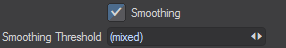
Parameters with input fields that have different settings for the selected surfaces will show (mixed) in the field. If textures are different, the T button will appear in an intermediate state. Differing colors will show as dashes in the color gadget. Changing a surface attribute changes it for all selected surfaces, including mixed states. Shift-clicking on the T or E button removes the texture or envelope for all selected surfaces.
Preset Shelf
If you would like to use the Preset Shelf, click its button on the interface. The Preset Shelf is a resizable floating window that holds a list of previews along with all of the associated settings in Modeler and Layout.
Basic Surface Parameters

All of the Numerical settings have mini-sliders. You can enter a numerical value into the input field or use the slider. The range of the slider is based on realistic settings; however, the input field will accept values beyond the maximum and minimum possible with the slider, including positive and negative values. Keep in mind that, except for maybe Luminosity, values outside the normal range of 0 to 100 percent will be unrealistic.
The surface attributes on the Material Tab are fundamental for virtually all objects. Each represents a particular characteristic of a surface’s appearance. At the top of these fundamental attributes is a Material Selector that allows you to jump directly to an appropriate material for your surface - making something metallic? Try Conductor. Something transparent? Try Dielectric (or try Principled BSDF for either). You may never have thought about it before, but if you look at the surface of objects around you, they differ by much more than their color. Are they shiny? Dull? Do they reflect other items in the room? Can you see through the material? These characteristics help you determine from what materials objects are made.
LightWave attempts to divide the different surface characteristics into controllable parameters. We will detail each Material, starting with the default of Standard.
There are also Material tools. These don't have much interactivity in the Surface Editor and should be edited in the Node Editor:
Shading Models
LightWave has multiple shading models on the second tab at the top of the Surface Editor window. The one you will use most often is probably Photoreal, but there is also Cel, Shadow Catcher, and Sublimation Cel Shader (created by famed Japanese anime studio Sublimation).
Bump Map
Nearly all real-world surfaces have some amount of texture or bumpiness. Such bumps are apparent due to the way light falls across the surface. A Bump Map is applied to a surface to give the appearance of a texture. However, no real geometry is added, and looking across the surface from the side could ruin the illusion. Shadows and edges can also reveal this lack of geometry in certain circumstances. The default setting is 100%.

Left: No Bump, Right: Bump at 500%. Note the silhouette is still perfectly round
If you want your bumps to actually displace geometry, try a Displacement Map in Object Properties > Deform.

Envelopes and Textures
Very few things in the real world have constant surface properties. Color patterns, discoloration, nicks, scratches can all subtly contribute to an object’s appearance. The real world is anything but consistent, but that is what makes things look real. The E and T buttons let you use envelopes and textures, respectively, instead of a static numerical value. The proper use of these features often results in a much more realistic surface.

Envelopes let you vary a value over time. For example, instead of Luminosity having the same value throughout your animation, it can differ on each frame. However, in any particular frame, it will have that value over the entire surface. To vary the value over the surface area, you must use a Texture.
Envelopes use the Graph Editor, and Textures are discussed in Texture Editor. While Envelopes are available on all Materials Texture buttons are only available on the Standard material. Applying textures to other Materials is done through the Node Editor.
Envelopes are not limited to surface values, so you will find Envelope E buttons throughout LightWave.
Surface Smoothing
Smoothing causes objects to appear to have smoothly rounded surfaces even though the object is composed of flat-faced polygons. To do this, LightWave uses a technique known as Phong shading. If the edges of two smooth-shaded polygons share vertices (points), they appear as one continuous, curved surface. The shared edge between them is no longer visible.


Left: No Smoothing, Right: Smoothing
Smooth Threshold
By default, LightWave will not smooth across two polygons if the angle between them is 90 degrees or greater unless you adjust the Smooth Threshold. This value adjusts the range of the smoothing function; it defines the angle beyond which LightWave will not smooth over the seam between adjoining polygons. The angle is measured using the surface normals of the adjoining polygons. If this angle is less than the Smooth Threshold, the surfaces are rendered smoothly. The default of 89.5° assures that any surfaces at right angles (90°) or greater to each other are not smoothed.
As with Bump Mapping, Smoothing does not change the surface’s geometry. As such, the edges of a ball can still expose the straight polygon nature of the object. If this becomes a problem, make the actual geometry smoother. You can use Modeling tools like Subdivide, for example.
Sharing Points
The concept of sharing points is vital in surface smoothing. Unlike the real world, objects, and their points, can occupy the exact same space. A simple cube has eight points and six sides. Any one point is shared by three sides. However, you can create a seemingly identical cube that doesn’t share any points or sides. Each side would be a totally independent polygon, thus there would be 24 points (six sides times four points).
The obvious reason for using shared points and sides is that it creates a more compact object. Remember, the simpler the object, the faster it renders, and the lower the number of resources used (i.e., RAM). However, sometimes, you will find that the polygons need to be separated.
Using Separation
Surface Smoothing can occur only where two polygons share all of the points along an edge. However, sometimes this smoothing is not what you want. For example, if you were Modeling something where you wanted a visible physical break, like a seam, you’d want to cut the polygons away and then paste them right back in. You may also find that when you have a flat surface that rounds over a corner, separating the flat polygons from the initial rounded polygons gives a more realistic look.


Left: Surface Smoothing, Right: Surface Smoothing with Separated Polygons
If you examine objects around you, you should notice that they all have seams. Very few objects in the real world are perfectly smooth, with edges that align. Separating polygons can add subtle detail to objects and give them a real-world look.
Separating polygons will double the points along the previously shared edge since each polygon now has its own set of those points.
Using the shortcut keys, Ctrl X and Ctrl V, to cut and paste is a quick way to separate polygons.
This technique lets you control smoothing by using a single surface name. Although you could create independent surfaces with identical settings - except one has smoothing on and the other does not - you may prefer to have one with smoothing on and use this separation technique to create the seam.
Vertex Normal Map
Although LightWave has no way of generating vertex normal maps internally yet, Layout can still work with them in objects obtained from other sources. This dropdown allows you to select the maps included with the object, or you can choose (none).
Clip Map
The Clip Mapping function, located on the Rendering Tab of the Object Properties Panel and in the Surface Editor, offers a way to quickly alter an object. Basically, it allows you to cut away portions of an object using a texture. This is a great way of creating 2D pop-ups, as well as holes, tears, or grids in objects without having to model them.
Double Sided
Sometimes it’s necessary to see both sides of a polygon, such as when you want to go inside a model (and wall thickness is not a concern). Also, if you import objects from other 3D modeling programs, either directly or through a conversion utility, some polygons may end up facing the wrong direction, which causes the object to render improperly. Click Double Sided to treat all polygons on the selected surface as two-sided.


Left: Single-Sided Polygons, Right: Double-Sided Polygons
As a consequence of using Double Sided, rendering time will increase because LightWave must calculate more polygons. Note also that Double Sided is only a surface attribute. The object, when loaded into Modeler, will show the true single-sided polygons.
Opaque

.png)

.png)
Dielectric without and with Opaque, Principled BSDF without and with Opaque
When surfaces are fully transparent, sometimes the shadows created by such surfaces are weak to non-existent. If you'd like to have solid shadows, use the Opaque switch to create a shadow as if from an opaque surface. Opaque also bypasses raytracing, meaning that shadows are created more rapidly than they would be tracing through transparent materials.