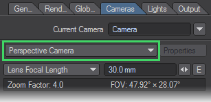
Camera Types
Zoom Factor
The zoom factor drop down menu for each camera type allows you to set a zoom factor equivalent to a real world camera lens. It has four different types of zoom factor for you to choose from, but LightWave defaults to a zoom factor of 3.2, equal to a 24 mm lens. LightWave users that are familiar with real world camera equipment may find that using the Lens Focal Length type on the drop-down menu is the easiest to use. Those who are solely used to LightWave’s way of doing things may be more comfortable using the Zoom Factor type. You can also use the Horizontal and Vertical FOV (Field of View) settings. These set the degree of angle of view.
Left:138 mm lens, Right: 8 mm lens
Smaller Zoom Factor or Lens Focal Length values will produce a wider angle lens effect while larger values give a narrow field of view, similar to a telephoto lens effect. You can create an envelope to achieve effects such as reverse zooms where you pull the camera away while concentrating the field of view. The envelope will be based on Zoom Factor regardless of which mode on the drop down you choose to use.
To correctly match the Camera to the Perspective viewport when using Match Viewport Perspective, set the Lens Focal Length to 30 mm.
Perspective Camera
The Perspective camera is LightWave's standard camera. It uses Unified Sampling and renders in packets.
Advanced Camera
The advanced camera is a multi-purpose camera. With the advanced camera, you can recreate real cameras and lenses. You can shift the lens distortion over time. Custom lenses can be created by using a mesh object
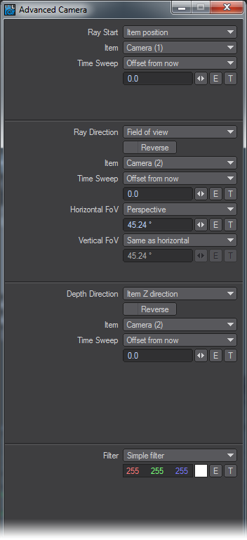
- Ray Start - This item defines the starting position for every Ray in the scene(world coordinate based)
- Item Position - this is used for pinhole type cameras(like the standard LW camera), that is a single point in space as a ray start position.
- Item - the item in the scene to be used as a camera
- Time Sweep : this can be used to control when in time to read the item position.
- UV Position on a mesh - camera plane defined as a UVmap on a mesh, I would probably recommend trying to stay within a semi-square plane as a starting point as you can get highly unpredictable results otherwise, the mesh itself can be animated in any manner(quite fun to play with)
- Mesh - well the mesh used for the camera plane.
- UV Map - Select the UV map you want to use
- Item XY - X and Y start position is taken from the Items coordinate system
- Item - what item to use as ray start
- Time Sweep - same as the item position Sweep function.
- Custom - definable with XYZ using numerical input, envelopes or textures
- Ray Direction - this defines where the rays should go once they leave the starting position, given in world coordinates.
- Reverse - The direction of the ray is reversed.
- Towards Item Position - Each ray goes through the origin of the item.
- Towards UV Position on a mesh - Each ray goes through the matching UV coordinates on a mesh.
- Mesh UV Polygon Normal - same as above but traverses the polygon normal instead of UV coordinates.
- Mesh UV smooth normal - same as above but with normal smoothing.
- Field of View - Behaves mostly like a perspective camera, aligning the rays to move along the Z axis in the FOV defined by the settings. This has a couple of sub-modes you can play with as well:
- Perspective - Standard perspective view with definable X and Y FOV
- Orthographic - Planar projection mode, area rendered is defined by the size of the ray start item.
- Cylinder - Y axis is orthographic while the X axis roams free, this is useful for making things like panoramas.
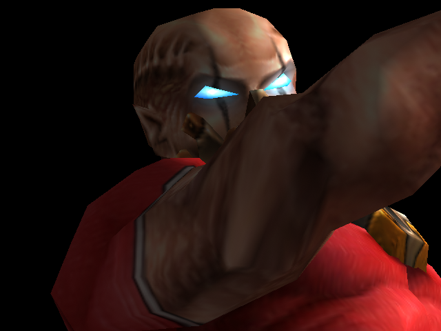
- Spherical - Produces a similar effect as a fisheye lens. The vertical settings will be disabled. The horizontal value controls how many degrees the fisheye lens covers. Note that this mode affects both horizontal and vertical FoV. The field of view has a default value of 45.24.
- Through item XY - rays set to go through item XY, dependant on ray start.
- Custom - Definable with XYZ using numerical input, envelopes or textures.
- Orientation Reference - Determines the orientation of the rays in relation to the selected item.
The depth direction setings are releated to a z-depth map. Normally, Item Z Direction will be the most used, or Same as Ray for a spherical camera, but those shots can be achieved with the Perspective, Shift, or VR cameras respectively. The others are provided for experimentation and are provided as an ultimate method of achieving a shot if more normal methods fail.
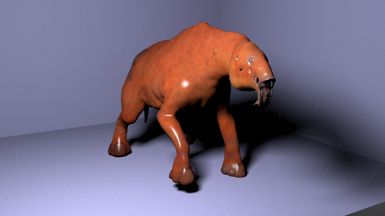
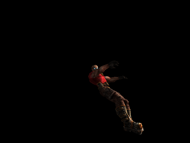
Standard Perspective Camera render
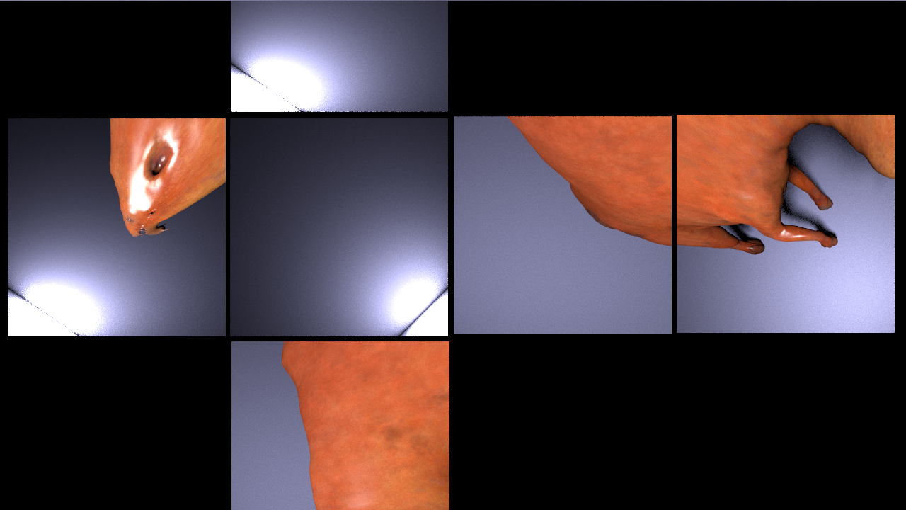
Example of Time Sweep
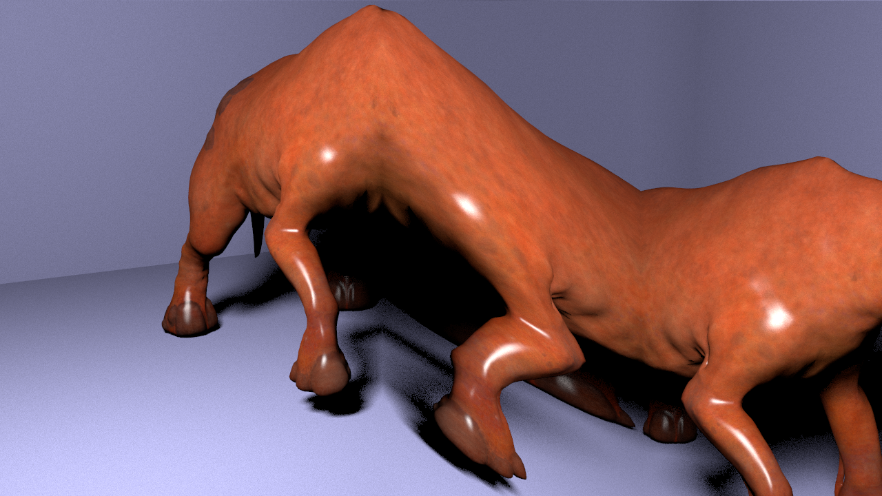
Example of Spherical Camera (camera moved in to the shoulder of the rasper cow)
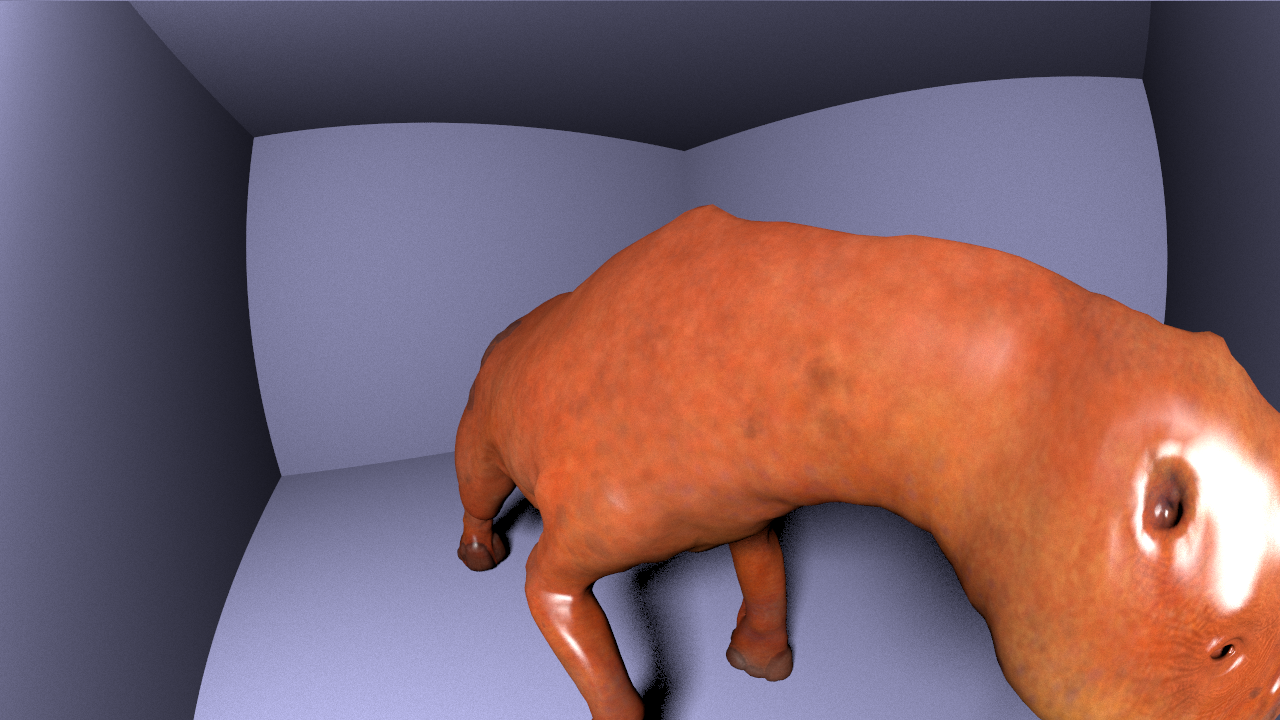
Example of Camera using UVMesh (view mapped to the UVs of the room)
Orthographic Camera
For the Orthographic Camera, the direction is the same for all rays, and the position is determined by the location of the corresponding pixel on the imaginary screen. Perspective of distance between objects is not possible when using the Orthographic camera. An example of using this camera is in top-down architectural renderings.
While it is possible to use the stereoscopic tools with the Orthographic camera, it is not recommended
Real Lens Camera
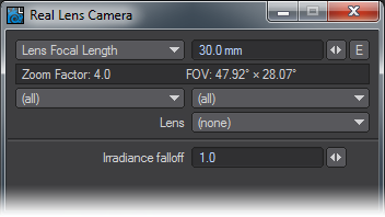
The Real Lens Camera Setting in the Camera Properties Panel will simulate a physical camera lens. Several camera manufacturers are listed and act as filters - selecting a particular manufacturer will limit the models and lenses shown.
Camera and Lens Menus
The first filter (top-left) will select the manufacturer of the camera. The second (top-right) filter will select the camera body. The third (bottom-right) filter will select the lens type.
If the first two filters are left at the default “All” selection, the Lens filter will show all lens types.
Irradiance falloff simulates the darkening towards the boundary of the image, much like a real camera. What is happening on a technical level is the brightness of a pixel is reduced as a function of the angle between the ray and the film plane.
The brightness is proportional to the cosine of the angle between the film plane normal and the ray direction, taken to some power given by the falloff value. So a falloff of 0 effectively disables it as the brightness will always be 1. Higher falloff values make the brightness drop off sharper and faster.
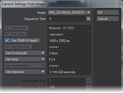
Load Image
The Real Lens camera can take its settings from the EXIF tags in an image or image sequence.The model selection dropdown in the Real Lens camera panel has an “(from image)” option. Selecting this opens a panel in which an image can be selected, and the settings to use from it picked.
There is also support for getting settings from image sequences. Image sequences should first be set up in the image editor. You can set the time in the sequence from which to get the settings.Some settings can be animated, which creates an envelope. Keyframes are set for all frames between the Scene Frame Start and End frame numbers (inclusive). If an image sequence is used, for each frame it will use the settings from the image matching the frame according to the sequence’s settings.
Limitations and cautions
- If Use Model is grayed out, even though a make and model is shown, it’s because the Real Lens camera doesn’t recognize it.
- There is no EXIF tag that says what lens is used. LightWave does put the lens info in the MakerNote for a rendered image, and it will use that if available. Otherwise, it will default to Standard.
- Focal distance is only rarely stored in the appropriate EXIF tag. Some of the most popular digital camera makers keep the focal distance in a proprietary MakerNote (presumably to get you to use their crappy photo software), if at all. Again, LightWave rendered images do store the focal distance correctly (if rendered with DoF).
- The focal length is the actual focal length, not converted to a 35mm film equivalent.
- Exposure is mapped to blur length using the current scene FPS setting and causes photorealistic motion blur to be turned on.
Shift Camera
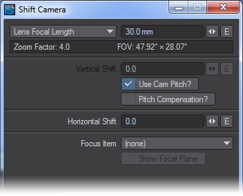
The Shift Camera is a tilt/shift type of camera capable of 2-point perspective views, popular for exterior renderings of building designs for architectural visualization. It works the same as the Perspective camera but removes the vertical perspective from the view. If part of the OpenGL preview is cut off, change the size of the grid with Fixed Near Clip turned off.
- Vertical Shift - Shifts the camera along the vertical plane. The Use Cam Pitch checkbox gives the original perspective correction behavior.
- Horizontal Shift - Shifts the camera along the horizontal plane.
- Focus Item - An arbitrary focus plane can be selected from a dropdown menu of objects. This creates a focal plane from the XY plane of the selected item, allowing items at different distances to remain in focus.
The focus plane can be toggled on/off by checking Show Focal Plane.
The camera must be kept horizontal and not banked, as unexpected results may occur in a render.
Surface Baking Camera
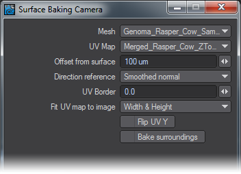
This camera considers each pixel as a UV coordinate, computing the position on a mesh polygon matching that UV coordinate, and shooting a ray at that position from close range.Unlike the Surface Baker shader it is multi-threaded, rendered by the raytracing renderer, it works with ScreamerNet, and works with VPR when not in Draft mode. Furthermore, as it produces a normal render, all the render buffers are available for saving.
The disadvantage is that only one mesh and UV map can be rendered at a time. However, you can set-up multiple cameras, each with its own mesh and map set, and render an animation that is setup to switch to a different camera each frame.
- Mesh - This is the object that you want to bake.
- UV Map - This is the map on that object that you want to use as the baker map.
- Offset from Surface - This is the distance from the mesh surface the ray should be shot from. Too large a value may mean that the ray encounters an intervening surface instead of the intended surface. Too small a value increases the possibility of floating point errors causing the ray to slip through the mesh surface instead of hitting it, or the ray direction to become erratic.
- Direction Reference - Ray directions can be set to be equal to the polygon normal, the smoothed polygon normal, or in the direction towards the origin of the mesh. The ray will still hit the same spot on the mesh. The difference is in the direction in which the ray approaches that point.
- UV Border - This is the ‘overdraw’ of the UV polygon boundaries. Using this setting, you can remove the visible seams in your UV projection.
- Fit UV map to image - This control just determines how to fit the map to the rendered image size. Fit both width and height, or just width or height.
- Flip UV Y - this inverts the map by flipping it around the “Y” axis.
- Bake Surroundings - This allows you to flip the rays around, thereby baking the surroundings instead of the mesh. Use for baking a reflection map or environment map.
Surface Baking Example
VR Camera
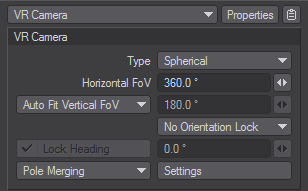
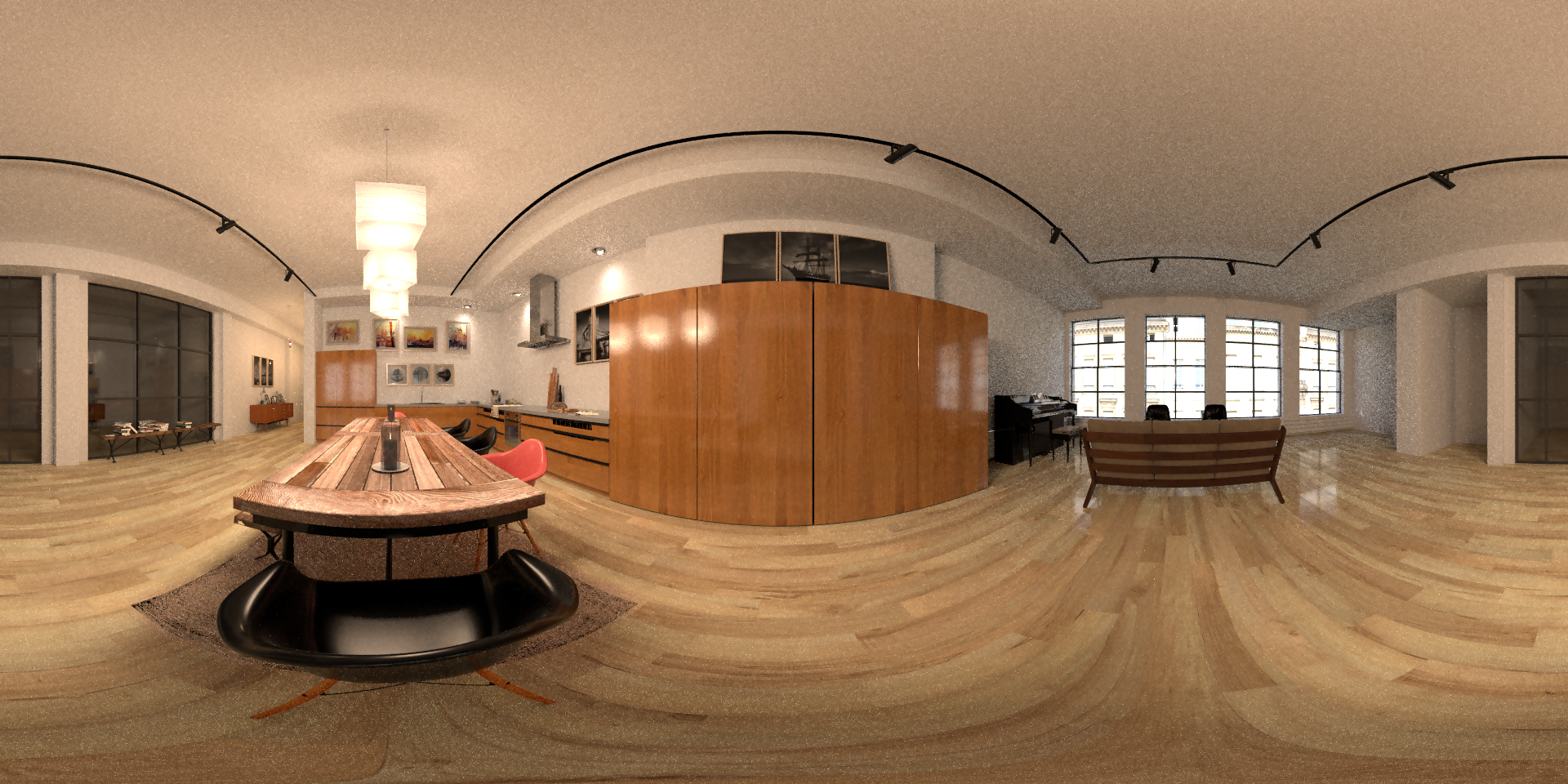
Interior Loft by Oscar Anchondo loaded into 2018 and rendered with a spherical VR camera but no other retouching
This camera is not displayable in OpenGL. Its effect is only visible through renders or VPR
The VR camera is available in two types. Both types have a horizontal and vertical field of view whose frustums are visible in OpenGL and the Cylindrical type can compute a vertical field of view automatically such that the aspect ratio is preserved (no stretching or squashing of the image). Straight ahead of the camera is the center of the view and stereoscopic rendering is supported.
Orientation Lock
The Orientation Lock dropdown is to allow the animator to orient it naturally while working for previs but remove the pitch and bank components when rendering. Presents three options:
- No Orientation Lock (Default) - Camera animation is possible in all three axes.
- Keep Upright (Parent) - Camera animation in Pitch or Bank has no effect relative to the parent item's coordinates (the parent's +Y direction defines upright for the camera)
- Keep Upright (World) - Camera animation in Pitch or Bank has no effect relative to world coordinates (the world +Y defines upright for the camera)
When the Orientation is locked to Parent or World a new option Lock Heading becomes available to restrict the camera's Field of View to straight ahead (or whatever angle is chosen) at render time.
Pole Merging
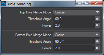
The spherical VR Camera has the option for pole merging, to control distortion near the poles. There are three modes:
- No Pole Merging - no pole merging takes place (default)
- Pole Merging - simple pole merging with settings for how to handle the top and bottom poles
- Use Nodal Pole - uses Nodal to set up more complex arbitrary pole merging
The simple pole merging option has the effect of reducing the eye separation to zero towards the poles. The settings control the falloff for each pole:
- Off - no falloff, pole merging is disabled for that pole
- Linear - linear falloff
- Cosine - a smoother falloff following a cosine curve (default)
The Threshold Angle specifies the vertical angle towards the pole at which the falloff will start to be applied. The eye separation falls off from full at that angle, to zero at the pole. Note that the threshold angle is not signed.
The Power value raises the falloff to a power. Larger values cause a more rapid falloff.
Use Nodal Pole
The nodal setup allows for arbitrary control of eye separation and convergence distance as a function of horizontal and vertical ray angle.
Input Node
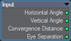
- Horizontal/Vertical Angle - Produces the horizontal and vertical angles of the ray (straight ahead is zero degrees; angles increase upwards and to the right; values are signed)
- Convergence Distance - If used, this value is taken from the Stereoscopic Rendering settings
- Eye Separation - If used, this value is taken from the Stereoscopic Rendering settings
VR Camera Output Node
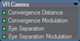
- Convergence Distance/Modulation - These work similarly to affect the convergence distance if Use Convergence Point is enabled in the stereoscopic rendering settings
- Eye Separation - When connected, the Eye Separation input specifies a new eye separation to be used for the ray. If not connected it defaults to the eye separation specified in the stereoscopic rendering settings
- Eye Separation Modulation - The Eye Separation Modulation interpolates between the eye separation from the stereoscopic rendering settings and the value provided to the Eye Separation input. If not connected, the Eye Separation input value is used. If connected, it linearly interpolates between the stereoscopic rendering setting eye separation (modulation value of 1), and the Eye Separation input (modulation value of 0)
When using the stereo render output, the VR Camera Export Image Filter should be used to define how renders are output.
Several new render presets have been included for use with the VR camera - VR HD, VR 2K and VR 4K.
Zoom Factor
The zoom factor drop down menu for each camera type allows you to set a zoom factor equivalent to a real world camera lens. It has four different types of zoom factor for you to choose from, but LightWave defaults to a zoom factor of 3.2, equal to a 24 mm lens. LightWave users that are familiar with real world camera equipment may find that using the Lens Focal Length type on the drop-downCp menu is the easiest to use. Those who are solely used to LightWave’s way of doing things may be more comfortable using the Zoom Factor type. You can also use the Horizontal and Vertical FOV (Field of View) settings. These set the degree of angle of view.
Left:138 mm lens, Right: 8 mm lens
Smaller Zoom Factor or Lens Focal Length values will produce a wider angle lens effect while larger values give a narrow field of view, similar to a telephoto lens effect. You can create an envelope to achieve effects such as reverse zooms where you pull the camera away while concentrating the field of view. The envelope will be based on Zoom Factor regardless of which mode on the drop down you choose to use.
To correctly match the Camera to the Perspective viewport when using Match Viewport Perspective, set the Lens Focal Length to 30 mm.
Perspective Camera
The Perspective camera is LightWave's standard camera. It uses Unified Sampling and renders in packets.
Advanced Camera
The advanced camera is a multi-purpose camera. With the advanced camera, you can recreate real cameras and lenses. You can shift the lens distortion over time. Custom lenses can be created by using a mesh object
- Ray Start - This item defines the starting position for every Ray in the scene(world coordinate based)
- Item Position - this is used for pinhole type cameras(like the standard LW camera), that is a single point in space as a ray start position.
- Item - the item in the scene to be used as a camera
- Time Sweep : this can be used to control when in time to read the item position.
- UV Position on a mesh - camera plane defined as a UVmap on a mesh, I would probably recommend trying to stay within a semi-square plane as a starting point as you can get highly unpredictable results otherwise, the mesh itself can be animated in any manner(quite fun to play with)
- Mesh - well the mesh used for the camera plane.
- UV Map - Select the UV map you want to use
- Item XY - X and Y start position is taken from the Items coordinate system
- Item - what item to use as ray start
- Time Sweep - same as the item position Sweep function.
- Custom - definable with XYZ using numerical input, envelopes or textures
- Ray Direction - this defines where the rays should go once they leave the starting position, given in world coordinates.
- Reverse - The direction of the ray is reversed.
- Towards Item Position - Each ray goes through the origin of the item.
- Towards UV Position on a mesh - Each ray goes through the matching UV coordinates on a mesh.
- Mesh UV Polygon Normal - same as above but traverses the polygon normal instead of UV coordinates.
- Mesh UV smooth normal - same as above but with normal smoothing.
- Field of View - Behaves mostly like a perspective camera, aligning the rays to move along the Z axis in the FOV defined by the settings. This has a couple of sub-modes you can play with as well:
- Perspective - Standard perspective view with definable X and Y FOV
- Orthographic - Planar projection mode, area rendered is defined by the size of the ray start item.
- Cylinder - Y axis is orthographic while the X axis roams free, this is useful for making things like panoramas.
- Spherical - Produces a similar effect as a fisheye lens. The vertical settings will be disabled. The horizontal value controls how many degrees the fisheye lens covers. Note that this mode affects both horizontal and vertical FoV. The field of view has a default value of 45.24.
- Through item XY - rays set to go through item XY, dependant on ray start.
- Custom - Definable with XYZ using numerical input, envelopes or textures.
- Orientation Reference - Determines the orientation of the rays in relation to the selected item.
The depth direction setings are releated to a z-depth map. Normally, Item Z Direction will be the most used, or Same as Ray for a spherical camera, but those shots can be achieved with the Perspective, Shift, or VR cameras respectively. The others are provided for experimentation and are provided as an ultimate method of achieving a shot if more normal methods fail.
Standard Perspective Camera render
Example of Time Sweep
Example of Spherical Camera (camera moved in to the shoulder of the rasper cow)
Example of Camera using UVMesh (view mapped to the UVs of the room)
Orthographic Camera
For the Orthographic Camera, the direction is the same for all rays, and the position is determined by the location of the corresponding pixel on the imaginary screen. Perspective of distance between objects is not possible when using the Orthographic camera. An example of using this camera is in top-down architectural renderings.
While it is possible to use the stereoscopic tools with the Orthographic camera, it is not recommended
Real Lens Camera
The Real Lens Camera Setting in the Camera Properties Panel will simulate a physical camera lens. Several camera manufacturers are listed and act as filters - selecting a particular manufacturer will limit the models and lenses shown.
Camera and Lens Menus
The first filter (top-left) will select the manufacturer of the camera. The second (top-right) filter will select the camera body. The third (bottom-right) filter will select the lens type.
If the first two filters are left at the default “All” selection, the Lens filter will show all lens types.
Irradiance falloff simulates the darkening towards the boundary of the image, much like a real camera. What is happening on a technical level is the brightness of a pixel is reduced as a function of the angle between the ray and the film plane.
The brightness is proportional to the cosine of the angle between the film plane normal and the ray direction, taken to some power given by the falloff value. So a falloff of 0 effectively disables it as the brightness will always be 1. Higher falloff values make the brightness drop off sharper and faster.
Load Image
The Real Lens camera can take its settings from the EXIF tags in an image or image sequence.The model selection dropdown in the Real Lens camera panel has an “(from image)” option. Selecting this opens a panel in which an image can be selected, and the settings to use from it picked.
There is also support for getting settings from image sequences. Image sequences should first be set up in the image editor. You can set the time in the sequence from which to get the settings.Some settings can be animated, which creates an envelope. Keyframes are set for all frames between the Scene Frame Start and End frame numbers (inclusive). If an image sequence is used, for each frame it will use the settings from the image matching the frame according to the sequence’s settings.
Limitations and cautions
- If Use Model is grayed out, even though a make and model is shown, it’s because the Real Lens camera doesn’t recognize it.
- There is no EXIF tag that says what lens is used. LightWave does put the lens info in the MakerNote for a rendered image, and it will use that if available. Otherwise, it will default to Standard.
- Focal distance is only rarely stored in the appropriate EXIF tag. Some of the most popular digital camera makers keep the focal distance in a proprietary MakerNote (presumably to get you to use their crappy photo software), if at all. Again, LightWave rendered images do store the focal distance correctly (if rendered with DoF).
- The focal length is the actual focal length, not converted to a 35mm film equivalent.
- Exposure is mapped to blur length using the current scene FPS setting and causes photorealistic motion blur to be turned on.
Shift Camera
The Shift Camera is a tilt/shift type of camera capable of 2-point perspective views, popular for exterior renderings of building designs for architectural visualization. It works the same as the Perspective camera but removes the vertical perspective from the view. If part of the OpenGL preview is cut off, change the size of the grid with Fixed Near Clip turned off.
- Vertical Shift - Shifts the camera along the vertical plane. The Use Cam Pitch checkbox gives the original perspective correction behavior.
- Horizontal Shift - Shifts the camera along the horizontal plane.
- Focus Item - An arbitrary focus plane can be selected from a dropdown menu of objects. This creates a focal plane from the XY plane of the selected item, allowing items at different distances to remain in focus.
The focus plane can be toggled on/off by checking Show Focal Plane.
The camera must be kept horizontal and not banked, as unexpected results may occur in a render.
Surface Baking Camera
This camera considers each pixel as a UV coordinate, computing the position on a mesh polygon matching that UV coordinate, and shooting a ray at that position from close range.Unlike the Surface Baker shader it is multi-threaded, rendered by the raytracing renderer, it works with ScreamerNet, and works with VPR when not in Draft mode. Furthermore, as it produces a normal render, all the render buffers are available for saving.
The disadvantage is that only one mesh and UV map can be rendered at a time. However, you can set-up multiple cameras, each with its own mesh and map set, and render an animation that is setup to switch to a different camera each frame.
- Mesh - This is the object that you want to bake.
- UV Map - This is the map on that object that you want to use as the baker map.
- Offset from Surface - This is the distance from the mesh surface the ray should be shot from. Too large a value may mean that the ray encounters an intervening surface instead of the intended surface. Too small a value increases the possibility of floating point errors causing the ray to slip through the mesh surface instead of hitting it, or the ray direction to become erratic.
- Direction Reference - Ray directions can be set to be equal to the polygon normal, the smoothed polygon normal, or in the direction towards the origin of the mesh. The ray will still hit the same spot on the mesh. The difference is in the direction in which the ray approaches that point.
- UV Border - This is the ‘overdraw’ of the UV polygon boundaries. Using this setting, you can remove the visible seams in your UV projection.
- Fit UV map to image - This control just determines how to fit the map to the rendered image size. Fit both width and height, or just width or height.
- Flip UV Y - this inverts the map by flipping it around the “Y” axis.
- Bake Surroundings - This allows you to flip the rays around, thereby baking the surroundings instead of the mesh. Use for baking a reflection map or environment map.
Surface Baking Example
VR Camera
Interior Loft by Oscar Anchondo loaded into 2018 and rendered with a spherical VR camera but no other retouching
This camera is not displayable in OpenGL. Its effect is only visible through renders or VPR
The VR camera is available in two types. Both types have a horizontal and vertical field of view whose frustums are visible in OpenGL and the Cylindrical type can compute a vertical field of view automatically such that the aspect ratio is preserved (no stretching or squashing of the image). Straight ahead of the camera is the center of the view and stereoscopic rendering is supported.
Orientation Lock
The Orientation Lock dropdown is to allow the animator to orient it naturally while working for previs but remove the pitch and bank components when rendering. Presents three options:
- No Orientation Lock (Default) - Camera animation is possible in all three axes.
- Keep Upright (Parent) - Camera animation in Pitch or Bank has no effect relative to the parent item's coordinates (the parent's +Y direction defines upright for the camera)
- Keep Upright (World) - Camera animation in Pitch or Bank has no effect relative to world coordinates (the world +Y defines upright for the camera)
When the Orientation is locked to Parent or World a new option Lock Heading becomes available to restrict the camera's Field of View to straight ahead (or whatever angle is chosen) at render time.
Pole Merging
The spherical VR Camera has the option for pole merging, to control distortion near the poles. There are three modes:
- No Pole Merging - no pole merging takes place (default)
- Pole Merging - simple pole merging with settings for how to handle the top and bottom poles
- Use Nodal Pole - uses Nodal to set up more complex arbitrary pole merging
The simple pole merging option has the effect of reducing the eye separation to zero towards the poles. The settings control the falloff for each pole:
- Off - no falloff, pole merging is disabled for that pole
- Linear - linear falloff
- Cosine - a smoother falloff following a cosine curve (default)
The Threshold Angle specifies the vertical angle towards the pole at which the falloff will start to be applied. The eye separation falls off from full at that angle, to zero at the pole. Note that the threshold angle is not signed.
The Power value raises the falloff to a power. Larger values cause a more rapid falloff.
Use Nodal Pole
The nodal setup allows for arbitrary control of eye separation and convergence distance as a function of horizontal and vertical ray angle.
Input Node
- Horizontal/Vertical Angle - Produces the horizontal and vertical angles of the ray (straight ahead is zero degrees; angles increase upwards and to the right; values are signed)
- Convergence Distance - If used, this value is taken from the Stereoscopic Rendering settings
- Eye Separation - If used, this value is taken from the Stereoscopic Rendering settings
VR Camera Output Node
- Convergence Distance/Modulation - These work similarly to affect the convergence distance if Use Convergence Point is enabled in the stereoscopic rendering settings
- Eye Separation - When connected, the Eye Separation input specifies a new eye separation to be used for the ray. If not connected it defaults to the eye separation specified in the stereoscopic rendering settings
- Eye Separation Modulation - The Eye Separation Modulation interpolates between the eye separation from the stereoscopic rendering settings and the value provided to the Eye Separation input. If not connected, the Eye Separation input value is used. If connected, it linearly interpolates between the stereoscopic rendering setting eye separation (modulation value of 1), and the Eye Separation input (modulation value of 0)
When using the stereo render output, the VR Camera Export Image Filter should be used to define how renders are output.
Several new render presets have been included for use with the VR camera - VR HD, VR 2K and VR 4K.