2D Textures
2D textures consist of images or procedurals that can be mapped to the object surface during the shading computation. An algorithm is used for “wrapping” the texture around the object’s surface so that the pattern curves and distorts realistically. The advantage of using 2D textures is that in using the projection methods available to them, the texture patterns can conform easily to basic geometrical shapes. Additionally, textures, in general, add apparent detail and so do not have to be modeled in geometry. An everyday use of a 2D texture might be to apply an image as a decal or label on a three-dimensional bottle or other object. 2D textures can also be used as transparency, reflection, refraction, normal, and displacement maps, etc.
The Blending input on these nodes refers to Blending Modes.
Bricks2D
Bricks2D is a simple brick-like 2D texture useful for very many patterns and effects that one would not normally expect just by considering its name. From broken glass and strange spider webs to more in line with what its name implies; such as roughly shaped cobblestone roads and brick walls.
The Bricks2D texture has axial projection methods available such as spherical, cubic, planar, front, cylindrical, and UV.
- Mortar Width (scalar) - Specifies the width of the mortar between the brick faces. Increasing this value will also reduce the face of the bricks in such a way that the pattern will repeat the number of U and V tiles within the defined scale of the texture correctly.
- Mortar Sharp (scalar) - Defiance how steep the falloff angle is between the brick faces and the bottom trough of the mortar area.
- Mortar Shift (scalar) - Mortar shift specifies the offset of the U directional mortar areas. When creating a standard red brick surface you can think of this value as determining the stagger amount of the bricks rows.
Edit Panel
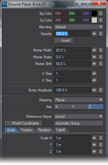
Here the Mapping projection types and Axis are not offered as node connections in the Workspace area. Likewise, Reference Object, World Coordinates, and Automatic Sizing are features exclusive to this node's Edit Panel. Please see the explanation for these items in the chapter that covers texturing with the Surface Editor.
CheckerBoard2D
Procedurally generated checkerboard pattern with axial projection methods such as spherical, cubic, planar, front, cylindrical, and UV.
Edit Panel
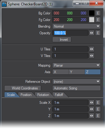
Here the Mapping projection type and Axis are not offered as node connections in the Workspace area. Likewise, Reference Object, World Coordinates, and Automatic Sizing are features exclusive to this node's Edit Panel. Please see the explanation for these items in the chapter that covers texturing with the Surface Editor.
Grid2D
Procedurally generated grid pattern. This grid pattern can vary the thickness of the lines that form the grid as well as define a soft edge falloff from line to center in user-specified amounts. It has axial projection methods available such as spherical, cubic, planar, front, cylindrical, and UV.
Grid2D is also extremely useful for visualizing results from the output of other nodes and network segments.
Unique Inputs
- Mortar Width (scalar) - Specifies the width of the mortar between the grid squares or “faces.” Increasing this value will also reduce the size of the face area of the grid in such a way that the pattern will repeat the number of U and V tiles within the defined scale of the texture correctly.
- Mortar Sharp (scalar) - Defiance how steep the falloff angle is between the grid faces and the bottom trough of the mortar area.
Edit Panel
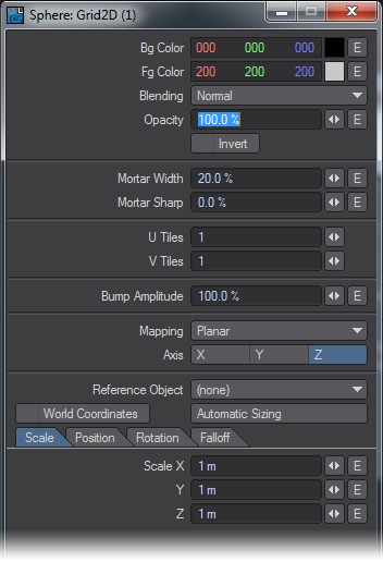
Here the Mapping projection type and Axis are not offered as node connections in the Workspace area. Likewise, Reference Object, World Coordinates, and Automatic Sizing are features exclusive to this node's Edit Panel. Please see the explanation for these items in the chapter that covers texturing with the Surface Editor.
Image
The description for this particular node could fill volumes and the use of images as applied to shading, texturing and lighting, has! This node is probably the single most useful and versatile node. The image node will allow you to load images with or without Alpha channels, map them directly onto polygons, and use various derived values from the image itself to control other nodes in the network.
The Image node has axial projection methods available such as spherical, cubic, planar, front, cylindrical, and UV.
It is worth mentioning here that while either images or procedurals by themselves can create stunning results, it is extremely advantageous to use procedurals and images together! You may find that when creating textures for photo-realistic or semi photo-realistic rendering, that procedurals can complement images and vice versa, in a way that far outweighs the use of either alone by themselves.
Edit Panel
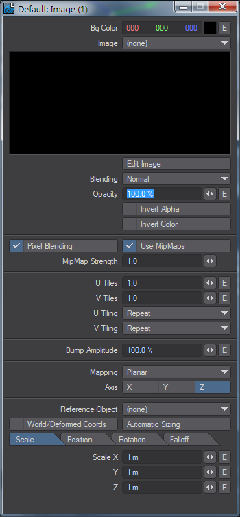
Here the Mapping projection type and Axis are not offered as node connections in the Workspace area. Likewise, Reference Object, World Coordinates, and Automatic Sizing are features exclusive to this node's Edit Panel.
Also please see the related sections elsewhere in this manual for descriptions of Pixel Blending, MipMap Quality, and MipMap Strength.
The explanation of the Image Map Layer Type in the Texture Editor found elsewhere in this manual differ concerning tiling methods, only in that the labels describing the menus are different.
Invert Alpha inverts the alpha portions of the image so that the alpha region becomes solid and non-alpha becomes transparent.
Invert Color inverts the color of the image.
Width Tile in the Texture Editor is U Tiling in the Node Editors’ Image node.
Height Tile in the Texture Editor is V Tiling in the Node Editors’ Image node.
The behaviors described for Reset, Repeat, Mirror, and Edge are the same as described for the Texture Editor.
![]() 2019.1 brings separate color channel outputs to the Image node.
2019.1 brings separate color channel outputs to the Image node.
Image Sampler
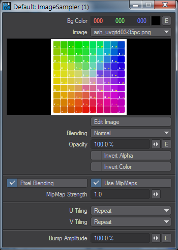
An image node that allows more external control than the standard Image node. It uses the Projection nodes to determine how the image will be attached to the surface. A Projection node isn't needed for intrinsic Object UVs so the Image Sampler's Color output can be plugged straight into the Color Input on a primitive shape.
Invert Alpha inverts the alpha portions of the image so that the alpha region becomes solid and non-alpha becomes transparent.
Invert Color inverts the color of the image.
![]() 2019.1 brings separate color channel outputs to the Image Sampler node.
2019.1 brings separate color channel outputs to the Image Sampler node.
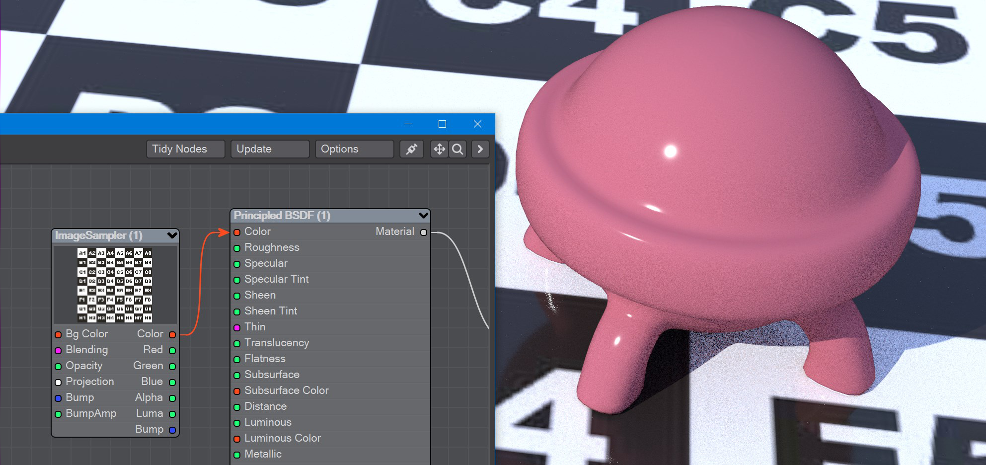
Texturing the plane does not need a projection because the plane is a primitive with intrinsic UV map.
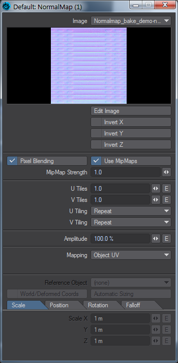
NormalMap
The normal map node allows you to load and utilize normal maps created from any of the various software packages that produce them such as ZBrush, Genetica Pro, or Marvin Landis’s free NormalMapCreate plugin for LightWave3D.
With descriptions of normal mapping technology being commonplace, we will highlight just a few of the main points you may want to consider when applying normal maps in LightWave3D. Namely what normals are in general, what happens when you apply a normal map, and a few of the differences between normal mapping and bump mapping.
It is easy to understand what normals are if we consider polygon normal or “geometric normals.” Polygon normals are just the direction in which a given polygon is facing - its facing or “normal” direction. Smoothed normals also consider smoothing interpolation. What’s happening when you apply a normal map is the replacement of that information with a set of directions contained in a map. The recorded directions are color encoded (RGB = the directions XYZ). This is different than standard bump mapping in that standard bump mapping does not replace the normal direction but rather modifies the existing directions. This is an important distinction because you’re replacing the direction the smooth shaded faces are facing when you apply a normal map, and the necessary cautions need to be taken to produce correct results.
Unique Inputs
- Amplitude (scalar) - Specifies the normal height or “amplitude” of the Normal directional vectors.
Using Alpha or luminance (connecting Color) values from other textures in the network along with their respective bumps can have the effect of blending the bump textures.
Can receive patterns or numerical values from other nodes in the network. This value can additionally be specified by user input by entering values into the Edit Panel of this node.
Since Bump Amplitude is a shading feature and not a displacement coordinate system value, it is specified as a percentage. Specifically, as a percentage of the texture value.
Edit Panel
Here the Mapping projection type and Axis are not offered as node connections in the Workspace area. Likewise, Reference Object, World Coordinates, and Automatic Sizing are features exclusive to this node’s Edit Panel. Please see the explanation for these items in the chapter that covers texturing with the Surface Editor.
Also please see the relative sections elsewhere in this manual for descriptions of Pixel Blending, MipMap Quality, and MipMap Strength.
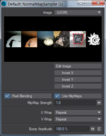
NormalMapSampler
An image node that allows more external control than the standard Normal Map node. It uses the Projection nodes to determine how the normal map will be attached to the surface.
Edit Panel
Parquet2D
Parquetry is the inlay of wood, often of different colors, that is worked into a geometric pattern or mosaic and is used especially for floors. The Parquet2D procedural texture offers the ability to create these geometric patterns. While a very common use would be for floor designs, the Parquet2D texture like other procedural textures, affords a great deal of creativity limited only by the imagination of the user. Parquet2D has axial projection methods available such as Spherical, Cubic, Planar, Front, Cylindrical, and UV.
Unique Inputs
- Tiles (integer) - This specifies the number of parallel planks or sections that each parquet tile is comprised.
Values below one will be evaluated as one.
Mortar Width (scalar) - Specifies the width of the mortar (or gaps) between the parquet faces. Increasing this value will also reduce the size of the face area in such a way that the pattern will repeat the number of U and V tiles within the defined scale of the texture correctly.
Mortar Sharp (scalar) - Defines how steep the falloff angle is between the parquet faces and the bottom trough of the mortar (or gap) area.
Edit Panel
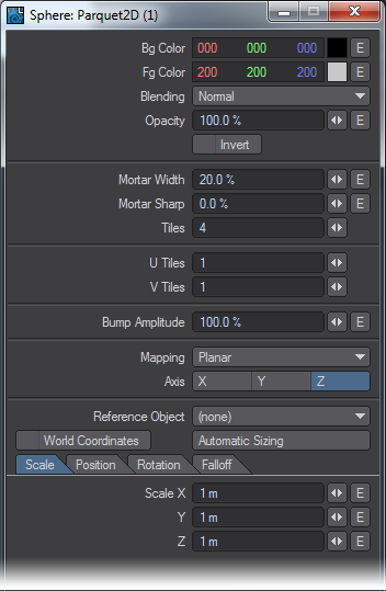
Here the Mapping projection type and Axis are not offered as node connections in the Workspace area. Likewise, Reference Object, World Coordinates, and Automatic Sizing are features exclusive to this node's Edit Panel. Please see the explanation for these items in the chapter that covers texturing with the Surface Editor.
Planks2D
The Planks2D procedural texture creates the gaps and faces of flush or staggered planks. Like Parquet2D, Bricks2D, Bricks3D, and other procedurals of this type a separate texture either procedural or image-based can be used where face and grout (mortar, gaps, etc.) materials are desired. Planks2D has axial projection methods available such as spherical, cubic, planar, front, cylindrical, and UV.
Inputs
- Mortar Width (scalar) - Specifies the width of the mortar (or gaps) between the plank faces. Increasing this value will also reduce the size of the face area in such a way that the pattern will repeat the number of U and V tiles correctly within the defined Scale of the texture.
- Mortar Sharp (scalar) - Defines how steep the falloff angle is between the plank faces and the bottom trough of the mortar (or gap) area.
- Stagger (scalar) - Stagger specifies the offset of the U directional gap (or “mortar”) areas. A value of 0% will cause all of the planks to line up flush on both ends, forming a straight row of planks.
- Can receive patterns and numerical inputs from other nodes in the network. Additionally, user input values may be entered in the Edit Panel for the node.
- Plank Length (scalar) - Specifies the length of the planks as a percentage to the overall size of the texture.
Edit Panel
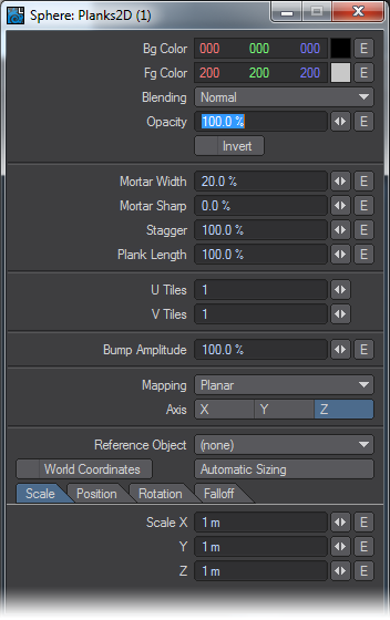
Here the Mapping projection type and Axis are not offered as node connections in the Workspace area. Likewise, Reference Object, World Coordinates, and Automatic Sizing are features exclusive to this node's Edit Panel. Please see the explanation for these items in the chapter that covers texturing with the Surface Editor.
Turbulence2D
A multipurpose noise texture with axial projection methods such as spherical cubic planar front cylindrical and UV.
Edit Panel
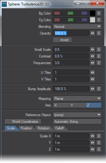
Here the Mapping projection type and Axis are not offered as node connections in the Workspace area. Likewise, Reference Object, World Coordinates, and Automatic Sizing are features exclusive to this node's Edit Panel. Please see the explanation for these items in the chapter that covers texturing with the Surface Editor.