3D Textures
Introduction
A 3D texture is computer generated via procedural algorithms with a set of parameters. The generated pattern follows logically inside the procedural volume and wherever polygonal surfaces exist in relation to that volume the procedural pattern information is applied. 3D textures can exist in world space coordinates or tied to an object’s center point when world coordinates is unchecked in the node’s Edit Panel. 3D textures avoid many of the difficulties attributed to the mapping of a bitmap around the surface of an irregular object. These textures have no edges and provide a continuous-looking appearance.
The Blending input on these nodes refers to Blending Modes.
Bricks
Bricks is a brick-like 3D texture useful in producing many patterns and effects. Modified, many elaborate variations divagating from conventionally recognizable brick patterns can be achieved.
Unique Inputs
- Thickness (scalar) - Is the thickness of the mortar areas of the brick pattern. As the thickness value increases the size of the brick faces decrease within a given texture scale creating the appearance of smaller bricks spaced farther apart.
- This value is in ratio to the texture scale. For example a value of 1.0 would produce a surface that was nothing but mortar with no visible brick faces. A value of zero would produce a surface of continuous brick faces with no mortar gaps and only hairline cracks that might be seen in very high precision stonework.
- Edge Width (scalar) - Is the width of the beveled edges which create a rounded or beveled look to the four sides of the brick face.
- This setting in ratio to the size of the brick face and is calculated as an offset along each side of each brick face.
- For example a value of 0.5 would produce a pyramid shape that would occupy the entire face area of each and every brick because 0.5 or halfway in from each edge of the brick is the entire brick face.
Edit Panel
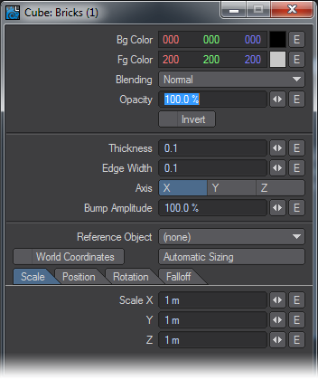
Axis is not offered as a node connection in the Workspace area. Likewise Reference Object, World Coordinates and Automatic Sizing our features exclusive to this nodes Edit Panel. Please see the explanation for these items in the chapter that covers texturing with the Surface Editor.
Checkerboard
Procedurally generated checkerboard pattern.
Edit Panel
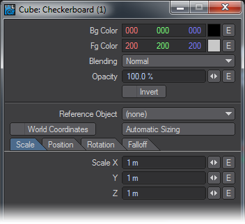
Reference Object, World Coordinates and Automatic Sizing are features exclusive to this node's Edit Panel.
Crackle
Cellular type texture good for amphibian type skin, scabs, rocks, gravel, asphalt, and etc.
Edit Panel
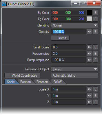
Reference Object, World Coordinates and Automatic Sizing are features exclusive to this node's Edit Pane. Please see the explanation for these items in the chapter that covers texturing with the Surface Editor.
Crumple
A cellular type texture good for a wide variety of uses including oceans, windy lake surfaces, to various types of rock, certain types of window glass, and etc.
Edit Panel
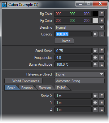
Reference Object, World Coordinates and Automatic Sizing are features exclusive to this nodes Edit Panel. Please see the explanation for these items in the chapter that covers texturing with the Surface Editor.
Crust
A cellular type texture that produces intersecting circular patterns and provides controls for transition gradients between the circular foreground and background colors.
Edit Panel
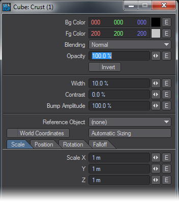
Reference Object, World Coordinates and Automatic Sizing are features exclusive to this nodes Edit Panel. Please see the explanation for these items in the chapter that covers texturing with the Surface Editor.
Dots
Procedurally generated three dimensional grid of ball-like texture elements.
Unique Inputs
- Diameter (scalar): - The Diameter value specified as a percentage, controls the “width” or diameter of the ball shapes that produce a circular look where an object surface intersects with the texture.
Since the sphere-like texture elements are aligned and spaced on a cubic grid by default it is entirely possible to apply this texture to a box or flat surface and see no results at all. What’s happening in this circumstance is that the balls are aligning on either side of the polygon surface. The surface plane essentially is passing through a part of the texture that contains no variant values - the space between the balls - and thus no visual results are produced.
In this situation, increasing the Diameter parameter to between 120% and 150% will allow you to see the results of the texture in VPR in order to interactively Position the texture at the optimal offset values.
Can receive patterns and numerical inputs from other nodes in the network. The user may also specify this value as a percentage using the controls available in the Edit Panel for this node.
Edit Panel
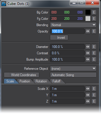
Reference Object, World Coordinates and Automatic Sizing are features exclusive to this nodes Edit Panel. Please see the explanation for these items in the chapter that covers texturing with the Surface Editor.
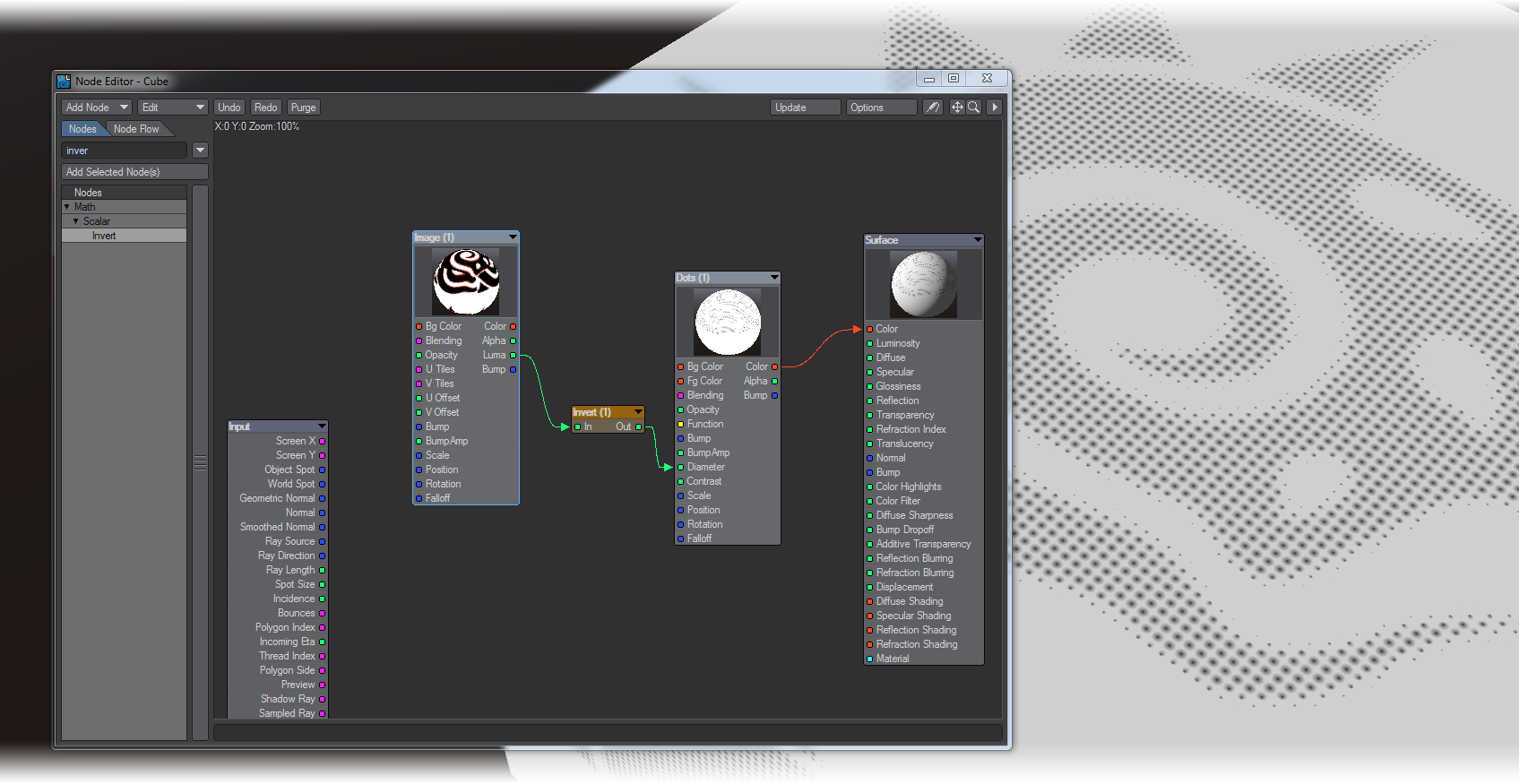
A simple offset Litho effect made by piping an image’s Luma into the Diameter value of Dots giving a halftone effect. The Scale value of Dots needs to be reduced and the Fg and Bg Colors should be reversed.
FBM
A fractional Brownian motion (FBM) fractal texture. The results of several scientific studies have shown that many real world natural textures have the same kind of spectra as produced by FBM making it a natural choice for various kinds of naturally occurring textures and patterns.
Edit Panel
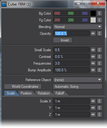
Reference Object, World Coordinates and Automatic Sizing are features exclusive to this nodes Edit Panel. Please see the explanation for these items in the chapter that covers texturing with the Surface Editor.
Flakes
Flakes is a procedurally-generated texture that simulates chips of glass or plastic.
Edit Panel
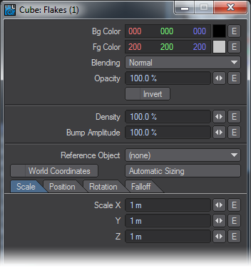
Reference Object, World Coordinates and Automatic Sizing are features exclusive to this nodes Edit Panel. Please see the explanation for these items in the chapter that covers texturing with the Surface Editor.
Grid
Procedurally generated grid pattern. This grid pattern can vary the thickness of the lines that form the grid and has the ability to define a soft edge falloff from line to center in user specified amounts.
- Width (scalar) - Defines the width of the grid square faces. If you think of this texture in terms of a tile pattern the width parameter defines the size of the tile plates in ratio to the mortar areas or grid lines.
A value of 100 % would be all title plates (squares) and a value of 0% would be all mortar areas (grid lines) in a mutually exclusive manner. - Contrast (scalar) - Controls the contrast amount between the foreground and background. Essentially this acts as a cubic bland or falloff between the background (grid squares) and the foreground (grid lines).
Values near 100% will produce very sharp transitions between grid squares and grid lines. Values near 0% will produce very soft linear gradient transitions between grid squares and grid lines.
Edit Panel
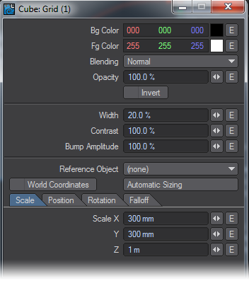
Reference Object, World Coordinates and Automatic Sizing are features exclusive to this nodes Edit Panel. Please see the explanation for these items in the chapter that covers texturing with the Surface Editor.
HeteroTerrain
An experimental prototype texture developed by Dr. Forest Kenton “Ken” Musgrave, Hetero Terrain is a fractal type texture that controls the amount of details added by successive overlays (called fractalizing) according to an “Offset” value. Edit Panel
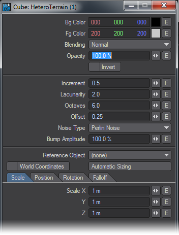
Reference Object, World Coordinates and Automatic Sizing are features exclusive to this nodes Edit Panel. Please see the explanation for these items in the chapter that covers texturing with the Surface Editor.
The Noise Type selection popup menu also remains a feature exclusive to this node’s Edit Panel. Without going beyond the descriptions offered in the Surface Editor section of the LightWave 3D manual for these related features, you can get a very good idea of what each Noise Type looks like by following these few simple steps:
- Set the texture Scale values small enough that you can see the full pattern of the texture on the geometry you’re working with.
- Set Increment to zero.
- Set Lacunarity to zero.
- Set Octaves to zero.
- Set the Offset value anywhere between 0.25 and 0.75
- And select the various Noise Types one at a time while watching the VPR preview update.
Honeycomb
A procedurally generated hexagonal honeycomb pattern. The Honeycomb texture node can be applied on an axial basis X, Y, or Z.
Unique Inputs
- Thickness (scalar) - Defines the thickness of the lines that form the hexagonal honeycomb pattern. This is in ratio to the size of the inner hexagons formed by the pattern. This means that increasing the thickness of the lines (Fg Color) will decrease the size of the inner hexagons (Bg Color).
Values approaching or above 0.25 will begin to distort the hexagonal shapes. Values between 1.0 and 2.0 will produce a staggered square grid pattern. A value of 2.0 or higher will cover the surface 100 percent solid in the foreground color with absolutely no pattern. - Edge Width (scalar) - Is the gradient falloff size of the pattern lines (foreground) into the hexagonal inner shapes. Increasing this value will have the apparent effect of decreasing the size of the inner hexagonal shapes.
The recommended value range for this parameter is 0.0 to 0.5. Higher or lower values may produce unexpected results. Values above 1.0 are not meaningful.
Edit Panel
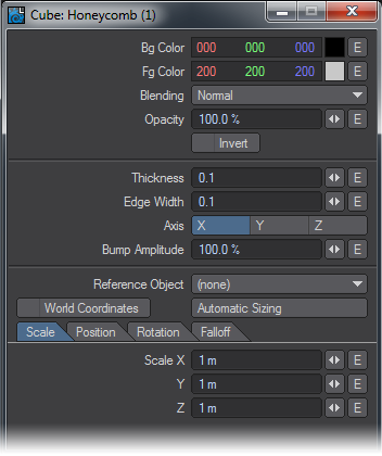
Axis is not offered as a node connection in the Workspace area. Likewise Reference Object, World Coordinates and Automatic Sizing our features exclusive to this nodes Edit Panel. please see the explanation for these items in the chapter that covers texturing with the Surface Editor.
Hybrid-MultiFractal
An experimental fractal prototype texture developed by Dr. Forest Kenton “Ken” Musgrave, Hybrid Multifractal attempts to control the amount of details according to the slope of the underlying overlays. Hybrid Multifractal is conventionally used to generate terrains with smooth valley areas and rough peaked mountains. With high Lacunarity values, it tends to produce embedded plateaus.
Edit Panel
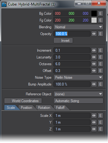
Reference Object, World Coordinates and Automatic Sizing are features exclusive to this nodes Edit Panel. Please see the explanation for these items in the chapter that covers texturing with the Surface Editor.
The Noise Type selection popup menu also remains a feature exclusive to this nodes Edit Panel. Without going beyond the descriptions offered in the Surface Editor section of this manual for these related features, you can get a very good idea of what each Noise Type looks like by following these few simple steps:
- Set the texture Scale values small enough that you can see the full pattern of the texture on the geometry you’re working with.
- Set Increment to zero.
- Set Lacunarity to zero.
- Set Octaves to zero.
- Set the Offset value anywhere between 0.25 and 0.75
- And select the various Noise Types one at a time while watching the VPR preview update.
Marble
A texture that produces a three dimensional grid of columns of marbly vein-like patterns. The Marble texture can be applied on an axial basis X, Y, or Z.
Unique Inputs
- Vein Spacing (scalar) - Defines the number and size of the veins within the given Scale value.
For example, given a uniform scale of 1m a Vein Spacing value of 1.0 would produce one vein per meter. A vein spacing value of 0.5 would produce two veins per meter, 0.25 four veins and so on. - Distortion (scalar) - Controls the amount of distortion or noise that is applied to the veins. This property is in direct correlation with Noise Scale.
- Noise Scale (scalar) - Controls the scale of the noise that is applied to the vein columns. This property is in direct correlation with the Distortion value.
- Contrast (scalar) - Sets the contrast of the texture value gradient. Higher values produce less gradient information between texture value extremes and therefore less noise is produced. The lower values spread the gradient more evenly between the extremes of the texture values and thus allow for more overall noise in the final output from this node.
- Frequencies (scalar) - “Frequencies” as used in this node is really just another name for octaves as defined in some of the descriptions of the fractal type textures within this document.
You can think of “Frequencies” as the number of levels of detail. At one “Frequency”, only the basic pattern is used.
Edit Panel
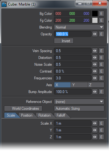
Axis are not offered as node connections in the Workspace area. Likewise Reference Object, World Coordinates and Automatic Sizing are features exclusive to this nodes Edit Panel. Please see the explanation for these items in the chapter that covers texturing with the Surface Editor.
MultiFractal
A multipurpose fractal type texture node.
Edit Panel
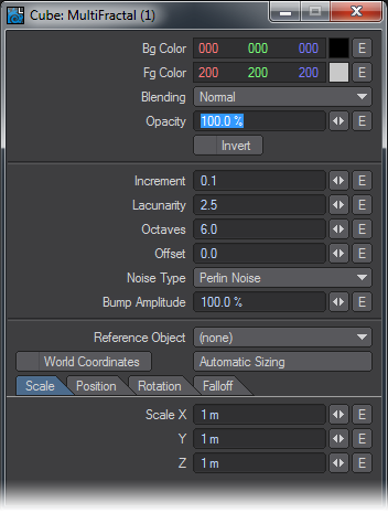
Reference Object, World Coordinates and Automatic Sizing are features exclusive to this nodes Edit Panel. Please see the explanation for these items in the chapter that covers texturing with the Surface Editor.
The Noise Type selection popup menu also remains a feature exclusive to this nodes Edit Panel. Without going beyond the descriptions offered in the Surface Editor section of this manual for these related features, you can get a very good idea of what each Noise Type looks like by following these few simple steps:
- Set the texture Scale values small enough that you can see the full pattern of the texture on the geometry you’re working with.
- Set Increment to zero.
- Set Lacunarity to zero.
- Set Octaves to zero.
- Set the Offset value anywhere between 0.25 and 0.75
- And select the various Noise Types one at a time while watching the VPR preview update.
 Procedural
This node, new to 2019, is a direct way to address the procedural textures in LightWave rather than using a Color Layer node or the 2D or 3D Procedural nodes. This node directly accesses the code used for the original layered implementation of the nodes and gives access to procedurals in third party collections not otherwise accessible other than in Color Layer nodes where you don't have the ability to manipulate the procedural with a Function input or change its Pos/Rot/Scale with another node input. If you wanted to get both a color and a bump map, you'd need two different Layer nodes, one for the color and one for the bump. Additionally, we have procedurals that don't have an equivalent 2D/3D node, and most of the nodes that have the same names in the 2D / 3D Procedurals don't match in appearance with these original procedurals.
Edit Panel
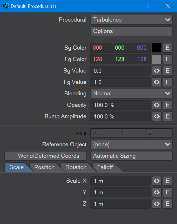
The specific procedural, native or 3rd party, can be chosen from the dropdown at the top of the window and if the procedural has specific options they can be accessed through the Options button below. The procedural node has Color, Alpha, Value and Bump outputs.
Ridged MultiFractal
An experimental fractal prototype texture developed by Dr. Forest Kenton “Ken” Musgrave, Ridged Multifractal is one of the best Fractal texture patterns to produce mountains, and mountainous terrain. It introduces highly detailed peaks and ridges often in similar shapes as naturally occurring mountain ranges. Control over the sharpness of the ridges can be achieved by adjusting the Threshold value. The Noise Types used are fairly critical in determining how mountainous the terrain should or should not be.
Edit Panel
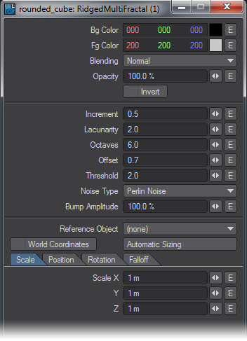
Reference Object, World Coordinates and Automatic Sizing are features exclusive to this nodes Edit Panel. Please see the explanation for these items in the chapter that covers texturing with the Surface Editor.
The Noise Type selection popup menu also remains a feature exclusive to this nodes Edit Panel. Without going beyond the descriptions offered in the Surface Editor section of this manual for these related features, you can get a very good idea of what each Noise Type looks like by following these few simple steps:
- Set the texture Scale values small enough that you can see the full pattern of the texture on the geometry you’re working with.
- Set Increment to zero.
- Set Lacunarity to zero.
- Set Octaves to zero.
- Set the Offset value anywhere between 0.25 and 0.75
- And select the various Noise Types one at a time while watching the VPR preview update.
Ripples
A procedural texture that produces a three dimensional ripple pattern.
Unique Inputs
- Wave Sources (scalar) - Defines the number of wave sources that interact with each other in order to create the overall Ripple texture effect.
Each wave source is a spherical ripple pattern. When a flat object surface for example, passes through the center of a wave source it appears very much alike to the effect one sees by throwing a stone into a body of very still water. - Wavelength (scalar) - Defines the wave length of the wave sources. This is the length or distance between the waves as measured peak to peak. This value is in ratio to the texture scale value meaning that if the texture scale was set to 1m for X, Y, and Z then a wavelength value of 1 would produce waves from each source exactly 1m apart. With the same scale if the wavelength value were set to 0.25 the results would be four waves per meter from each source as defined by the Wave Sources parameter.
- Wave Speed (scalar) - Defines the speed of the wave in terms of distance from peak to peak per frame. For example given a Wave Length of 0.25 if the desired cycle point was at 60 frames into the animation the Wave Speed value would be 0.004166666667. This is the resulting number from dividing 0.25 by 60 (0.25/60).
Edit Panel
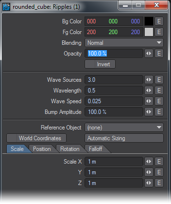
Reference Object, World Coordinates and Automatic Sizing are features exclusive to this nodes Edit Panel. Please see the explanation for these items in the chapter that covers texturing with the Surface Editor.
Turbulence
The general purpose fractalized noise texture, Turbulence is good for various aspects of naturally occurring phenomena such as fire, water, wind, smoke, clouds, or adding dirt, grime, and age to otherwise clean it computer graphic looking surfaces.
Edit Panel
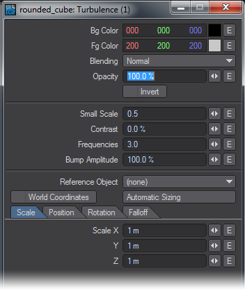
Reference Object, World Coordinates and Automatic Sizing are features exclusive to this nodes Edit Panel. Please see the explanation for these items in the chapter that covers texturing with the Surface Editor.
Turbulent Noise
A multipurpose turbulent noise texture good for a wide variety of applications.
Edit Panel
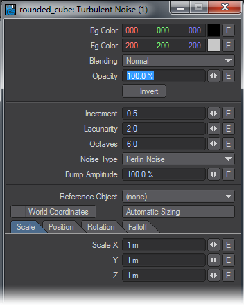
Reference Object, World Coordinates and Automatic Sizing are features exclusive to this nodes Edit Panel. Please see the explanation for these items in the chapter that covers texturing with the Surface Editor.
The Noise Type selection popup menu also remains a feature exclusive to this nodes Edit Panel. Without going beyond the descriptions offered in the Surface Editor section of this manual for these related features, you can get a very good idea of what each Noise Type looks like by following these few simple steps:
- Set the texture Scale values small enough that you can see the full pattern of the texture on the geometry you’re working with.
- Set Increment to zero.
- Set Lacunarity to zero.
- Set Octaves to zero.
- Set the Offset value anywhere between 0.25 and 0.75
- And select the various Noise Types one at a time while watching the VPR preview update.
Underwater
A procedural texture that produces double interlocking rebel patterns per wave source in order to approximate wavy water refraction patterns.
Unique Inputs
- Wave Sources (scalar) - Defines the number of wave sources that interact with each other in order to create the overall Ripple texture effect.
Each wave source is a spherical double ripple pattern. When a flat object surface for example, passes through the center of a wave source it appears very much alike to the effect one sees by throwing a stone into a body of very still water. - Wavelength (scalar) - Defines the wave length of the wave sources. This is the length or distance between the double wave pattern. This value is in ratio to the texture scale value meaning that if the texture scale was set to 1m for X, Y, and Z then a wavelength value of 1 would produce waves from each source exactly 0.5m apart. The reason we arrive at the value of 0.5 is because as mentioned this is a double wave pattern - meaning two concentric waves.
- Wave Speed (scalar) - Defines the speed of the waves in terms of distance from peak to peak per frame. For example given a wave length of 0.25 if the desired cycle point was at 60 frames into the animation the Wave Speed value would be 0.004166666667. This is the resulting number from dividing 0.25 by 60 (0.25/60).
- Band Sharpness (scalar) - Controls the sharpness of the gradient between wave peaks and valleys.
Edit Panel
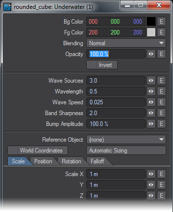
Reference Object, World Coordinates and Automatic Sizing are features exclusive to this nodes Edit Panel. Please see the explanation for these items in the chapter that covers texturing with the Surface Editor.
Veins
A three dimensional cellular type texture that produces vein-like texture patterns.
Unique Inputs
- Width (scalar) - Controls the width in percentage, of the veins. Smaller values produce narrower sharper veins.
- Contrast (scalar) - Defines the amount of contrast in percentage values, between the vein areas and the spaces in between the veins.
Edit Panel
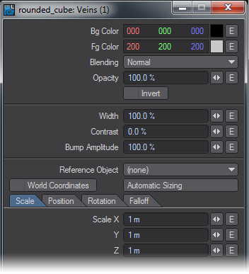
Reference Object, World Coordinates and Automatic Sizing are features exclusive to this nodes Edit Panel. Please see the explanation for these items in the chapter that covers texturing with the Surface Editor.
Wood
A three dimensional procedural texture that produces wood like ring patterns. This texture is not intended to produce a “photo-real” wood texture by itself alone but rather supply the user with the basic framework of a wood texture allowing users the freedom to add the kind of grain patterns and other details needed to produce the desired results.
Wood offers the ability to scale the transition gradient ramp of the rings.
Unique Inputs
- Frequencies (scalar) - Defines the number of noise frequencies (0~31) used to affect the basic ring pattern. Each frequency introduces compound affecting noise patterns.
- Turbulence (scalar) - Defines the amount of influence each frequency will have on the basic ring pattern. This setting is in ratio of to texture Scale value.
- Ring Spacing (scalar) - Defines the spacing value between rings in terms of layout units usually meters. As opposed to some other seemingly similar textures the Wood texture Scale value has no affect on ring spacing.
- Ring Sharpness (scalar) - Controls the position of the end of the gradient ramp from the foreground color or ring start, to the background color also offset from the ring start edge.
You can think of each concentric ring as having a highly defined leading edge or “start” position and the Ring Sharpness as defining the thickness of each ring where the thickness is always a gradient from the foreground to the background color.
Higher values produce narrower rings while lower values produce wider rings. A value of about 4 will produce a gradient ramp length that ends in about the middle of the ring before the affecting Turbulence is applied.
Edit Panel
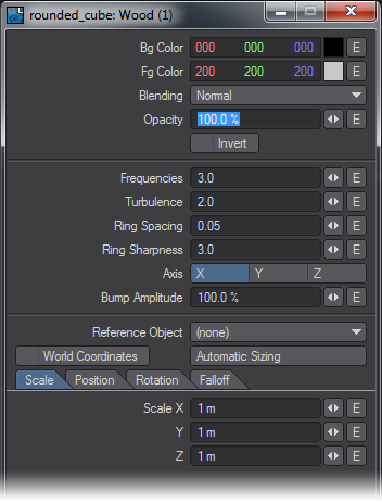
Axis are not offered as node connections in the Workspace area. Likewise Reference Object, World Coordinates and Automatic Sizing our features exclusive to this nodes Edit Panel. please see the explanation for these items in the chapter that covers texturing with the Surface Editor.
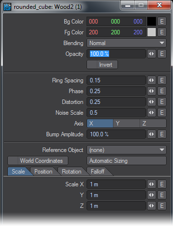
Wood 2
A three dimensional texture that produces a would like pattern of concentric rings. Wood2 offers the ability to phase the transition gradient ramp of the rings.
Unique Inputs
- Ring Spacing (scalar) - Defiance the ring spacing in relationship to the texture Scale value. For example with a scale value of 1m for X, Y, and Z , a Ring Spacing value of 0.5 would result in a ring every 50cm or 2 rings per meter.
- Phase (scalar) - The Phase value phases or “moves” the gradient transition in respect to the ring inner (start) and outer (end) edges.
Smaller values place the background to foreground gradient ramp start nearer the inner edge of the ring. Larger values place the gradient start nearer the outer edge of the ring.
A Phase value of 0.5 will center the gradient peak between the beginning and end of the ring width.
The length of the gradient ramp is equal to the span of a single ring. - Distortion (scalar) - Defines the amount of influence that Noise Scale may introduce to the shape of the rings.
Depending on the value of the noise scale this has the effect of “distorting” the otherwise concentric circular shape of the rings. - Noise Scale (scalar) - Defines the scale of the single noise pattern.
Smaller values result in a smaller noise scale.
Edit Panel
fBm Noise
A fractional Brownian motion (fBm) fractal noise texture. The results of several scientific studies have shown that many real world textures have the same kind of spectra noise as produced by fBm making it a natural choice for various kinds of naturally occurring texture noises and patterns.
Edit Panel
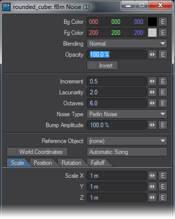
Reference Object, World Coordinates and Automatic Sizing are features exclusive to this nodes Edit Panel. Please see the explanation for these items in the chapter that covers texturing with the Surface Editor.
The Noise Type selection popup menu also remains a feature exclusive to this nodes Edit Panel. Without going beyond the descriptions offered in the Surface Editor section of this manual for these related features, you can get a very good idea of what each Noise Type looks like by following these few simple steps:
- Set the texture Scale values small enough that you can see the full pattern of the texture on the geometry you’re working with.
- Set Increment to zero.
- Set Lacunarity to zero.
- Set Octaves to zero.
- Set the Offset value anywhere between 0.25 and 0.75
- And select the various Noise Types one at a time while watching the VPR preview update.