Projections
Image Map Projection
Since images are usually rectangular and surfaces may or may not be, you must tell LightWave how you want the image map projected onto the surface. The common projection types settings are Planar, Cylindrical, Spherical, Cubic, Front and UV.
Generally, you should pick the shape that best describes the surface shape. (Note that this is not necessarily the object’s overall shape since that may be made up of many surfaces.) For example, if you were mapping a label image on the sides of a soda can, you’d use Cylindrical. For a planet, you’d use Spherical. For a wall, Planar would do the trick. For a brick, Cubic might be best.
What about a die? Cubic? This may be a trick question. Since a die has a different number of dots on each side, you’d use a different Planar map on each one.
Standard Image Mapping tools (i.e., planar, cylindrical, and spherical mapping) may be somewhat limiting when the surface is irregular in shape. These techniques usually work well only in cases where the entire texture image can be globally mapped using a linear interpolation along two axes. The object geometry essentially has no influence on how the texture is applied.
However, what if you could assign areas of a texture image to points on the surface, essentially tacking it down at key points? This is what UV Mapping in Modeler allows you to do. Between the tacks, the image is stretched smoothly.
The projections nodes are for determining how images are mapped when using the Image Sampler and Normal Sampler nodes.
Cubic
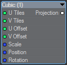
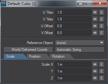
Replicates the Surface Editor Cubic image mapping available in LightWave.
Cubic Projection
Cubic projection is essentially the same as Planar, except that you cannot select a Texture Axis. Cubic projects the image from all three axes at the same time. The image is projected like Planar, except simultaneously along all three axes. Use Cubic when you wish to apply the same image to all sides of a rectangular shape, such as an image of tiling bricks wrapped around the sides of a building, or wallpaper on the walls of a room.
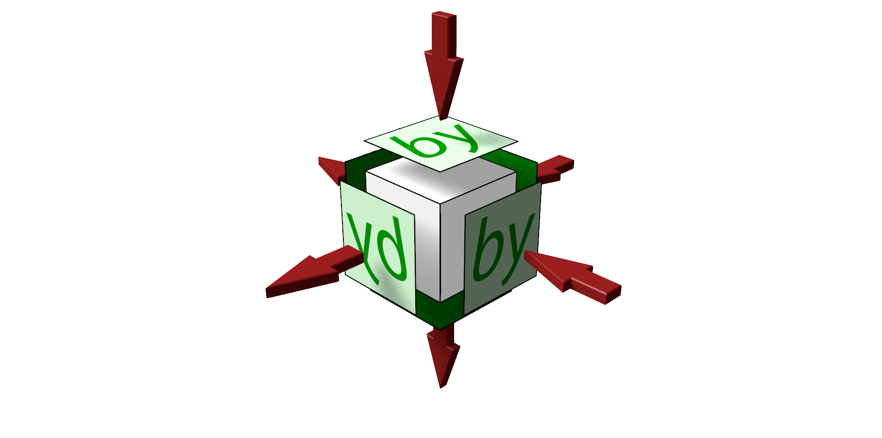
Note that Cubic Projection projects along the X, Y and Z axes and objects merely intersect these projections. This means that images like text will only be correct on three sides, the others will be reversed as shown here with the images that have the arrow coming out of them rather than going in. Creating an item like a dice needs six planar projections to be correct.
Cylindrical
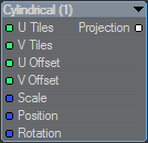
Replicates the Surface Editor Cylindrical image mapping available in LightWave.
Cylindrical Projection
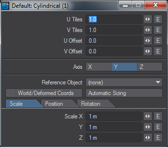
Cylindrical projection wraps an image around the selected axis like a paper towel wrapped about a cardboard tube. By default, an image is wrapped so it covers the surface once, allowing the side edges of the image to meet on the back of the surface. A soda can and a tree trunk are both good examples of surfaces that would use Cylindrical projection.

Cylindrical projection is always wrapped around a surface so that the top of the image appears towards the positive axis side of the Texture Axis.
Front

Replicates the Surface Editor Front image mapping available in LightWave.
Front Projection
The concept of Front projection is very simple and quite similar to a chroma-key effect. However, instead of applying an image where a color screen is, it replaces the selected surface(s) with a selected image.

In most cases, the image you select for a Front Projection Map is the same image you use for the Background Image on Layout’s Compositing Tab of the Effects Panel (Windows > Compositing Options).

Scale, Position, and so on, are not relevant with Front projection. It is always the size (and frame/pixel aspect) it would be if loaded as a Background Image. As such, changing the Resolution or Pixel Aspect Ratio on the Camera Properties Panel will also affect the Front projection.Front projection is used primarily for comp (compositing) work where you combine LightWave objects with a live-action background image or sequence. A common example occurs when you want a LightWave object to cast a shadow (believably) onto the image or behind a portion of the background image.
The image used in the surface and the background will pin-register the surface to the background, letting you go in front or behind. Your object then appears to interact with the environment. You can cast shadows or cause reflections from a regular 3D object onto the surface that is front projection mapped.


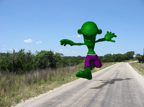
Front-Projection mapped Ground surface catches the character’s shadow.
The ground object is just a flat box with Front Projection Image Mapping that uses the same image as the background. Its job is merely to catch the object’s shadow.
Another example is to use an image of trees as your background image and fly a UFO between them so the UFO appears to go in front of some trees and behind others. All you need to do is model some rough shapes that match the trees you wish to fly behind (they could even be flat planes).
Another good example for Front projection is to create a flat plane and align it to an image of an ocean or a lake. Front projecting the water surface onto it lets you place an object beneath the water and push it through the surface. Submarines and sea creatures will appear to break the surface this way.
The hardest part of Front projection is aligning the objects, matching lighting, and getting the right camera angle. Using Background Image as the Camera View Background on Layout’s Display Options Tab of the Preferences Panel (Edit > Display Options) will allow you to do all that. You also must search for the right balance of Luminosity and Diffuse for the Front projection surface so that the object’s true shape is not revealed by shading.
NOTE: Don’t use the Soft Filter (Camera Properties Panel) with Front projection. It will soften only the image used on the object surfaces, not the background.
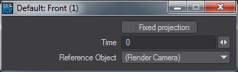
Fixed Projection
Front projection surfaces will always look the same no matter where you move the object or which way you rotate it. The image does not normally stick to the surface. However, if you activate the Fixed Projection option (previously Sticky Projection), it fixes (i.e., locks) the projection from the camera’s perspective at the specified Time.
The default unit of measure for Time depends on the Frame Slider Label setting on the General Options Tab of the Preferences Panel in Layout or the Time Format setting on the Display Options Panel, Units Tab in Modeler. You may specify the unit of measure by appending f for frames or s for seconds to the entered number (e.g., 22f for frame 22, 31s for 31 seconds). You may also enter SMPTE time code, like 00:00:01:16 for one second, frame 16. The entry is converted to the default unit of measure.
Use Fixed Projection to create parallax with two-dimensional images by using a technique called Camera Mapping. (Use the Reference Camera setting to select the camera, if you have multiple cameras in your scene.)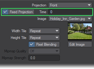
Essentially, you set the frame where the texture will be pin-registered to the background (like normal Front Projection Mapping). On all other frames, the texture is stretched to compensate for more or less of the texture being visible, which is caused by factors like the camera being moved.For example, in a picture of some buildings, you could place the LightWave camera in the same place as the original camera in relation to some simple 3D buildings; then, you could project the picture onto the buildings and lock it at frame 0. You’ll need a doctored background image/object - with Fixed projection - to reveal what’s behind the buildings. If you move the camera forward, it will appear to fly into or around the buildings.
Use your paint program’s rubber stamp function to erase areas where background Fixed projection surfaces will be revealed.
Obviously, there are great limitations in getting three-dimensional data out of a two-dimensional picture. However, short slow-moving sequences can be quite realistic.
Using the Shadow Catcher workflow offers a more modern way of achieving the result
Planar
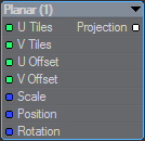
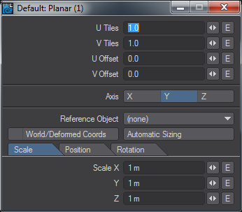
Replicates the Surface Editor Planar image mapping available in LightWave.
Planar Projection
Planar projection will project an image onto a surface as if you were projecting the image through a slide projector onto a wall. Planar Image Maps are best used on flat, or nearly flat surfaces like the sides of buildings and the screens of video monitors.

For the X and Y axes, Planar images are projected from the positive axis side of a surface towards the negative axis side. This means that the image appears correct when viewed from the positive side and it appears reversed if you view it from the negative side. For the Z axis, Planar images are projected from the negative side.
If you encounter this reversing effect and it isn’t what you want, you can reverse an image back by making the Scale value negative for the axis that needs to be reversed.
Spherical
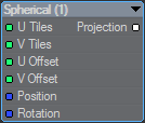
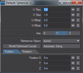
Replicates the Surface Editor Spherical image mapping available in LightWave.
Spherical Projection
Spherical projection wraps an image around a surface as if you were stretching a flat piece of rubber around a ball, but without having to worry about the edges all meeting. Planets, basketballs, and marbles could all use Spherical projection.

Spherical projection does not use Scale parameters. Images are wrapped completely around the surface (using the Wrap values, discussed later). Spherical projection is always oriented so that the top of the image appears toward the positive side of the Texture Axis.
UV
Replicates the Surface Editor UV mapping available in LightWave.
UV Texture Maps
The U and V refer to Texture Map coordinates and are really not very different from the XYZ coordinates you are familiar with. In fact, UV Mapping is the process of setting up a relationship between the two dimensions of an image, U and V, with the three dimensions of an object surface, XYZ.
Once this relationship is set up, changing any parameter (i.e., U, V, X, Y, or Z) will also relatively change the appearance of the Texture Mapping. With UV Mapping, the object provides additional information for Texture Mapping, which can be different for any given point on the surface. The texture is more or less stuck to points on the surface using a relationship that you define.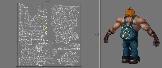
UVs and Projection
UVs have to come from somewhere. For existing polygonal models, the choices are limited to setting the UV coordinates for each point in the object manually, or applying some projection, which automatically generates the 2D Texture coordinates from the given 3D point positions. In LightWave, you can create UVs by using projections, which also happen to be the same as the standard projections for Texture Mapping (i.e., Planar, Cylindrical, and Spherical).Usually, the projection for the UV Map is not suitable for the whole model. The projected UV Map must be tweaked - eyes and nostrils moved over the right parts of a face, or texture features matched to geometry features.
Keep in mind that standard Projection Mapping is more accurate because it has some exact, continuous value over the entire surface. UV Mapping, on the other hand, is technically accurate only at small sample points. The surface for the large areas in between the sample points is interpolated. Adjusting the sample points so that the interpolated areas look right is difficult and the reason why UVs are more difficult to use.
For illustration purposes, let’s say you had your texture image printed on a piece of very flexible rubber and wanted to fit it on a toy car made of wood. You could conform the rubber material to contours of the car by tacking it down with thumbtacks. That is more or less what UV Mapping does. However, it is slightly reversed: what you do is tack the UV points down onto the image. Alternatively, imagine that your image is printed onto flat paper and you use an advanced form of Origami to fold it into shape.

Using projections with Object UVs from Primitive Shapes is not necessary. You can pipe the Image Sampler node with your image directly into the input you want on the surface of a Primitive Shape
Anisotropy requires that there is a Projection node input otherwise you will get strange polygonal shapes in the render.


Left: Anisotropy at 100 %, Rotation at 15 %, Roughness at 30 %. Right: No Projection
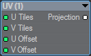
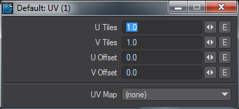
UV Tiles and Offsets
In all cases, except Front, Projections include Tiles and Offsets options. These options apply equally to images that are not UV mapped, despite their naming, and simply refer to the horizontal (U) and vertical (V) directions. Using tiles and offsets it is possible to tile image maps over the polygons of a surface. It can also be used as a way of offsetting UDIM tiles.