Rounder Tool
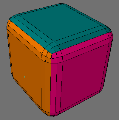
The Rounder tool (Multiply > Extend > Rounder) will bevel, smooth edges and generally round off geometry on a closed mesh in a variety of ways. It rounds based on point selection, bevels edges, smooths corner edges, has interactive controls, presets and more.


Selecting Edges
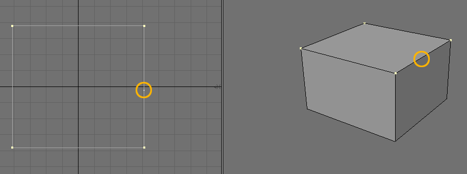
The edges you want to round are selected by selecting the edges or points at either end of the edge - illustrated below, or selecting the edge in Edge mode:


If no points are selected, as with other Modeler tools, Rounder will assume all the points have been selected (and hence round all edges/points).
If the selected object is small in scale and Rounder is activated, the default values may make the object explode in size. If this happens, open the Numeric Panel and reduce the Inset Scale.


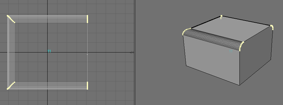
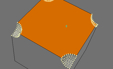
With the above method of edge selection it is NOT possible to select all but one edge of a polygon (eg. to round three edges of a square on one side of a cube). As shown on the left, if all four points are selected then the polygon is beveled.


To only round three edges (of the four), add an extra point to the edge you don’t want rounding.
Selecting Polygons
If no polygons are selected, Rounder will scan all the polygons of the object. If you are only rounding a few edges of an object containing a large number of polygons you can speed up the action of Rounder by selecting the polygons containing only the points/edges you are rounding.
When selecting polygons make sure you select all the polygons adjacent to the edges/points you are rounding, otherwise Rounder will generate an error.
Clean Geometry. An important part of not generating errors with Rounder is to ensure the geometry is clean:
- Rounding edges must be shared by exactly two polygons.
- Polygons containing rounded edges must be planar.
- Make sure no isolated points or two-point polygons are selected
The Rounder Numeric Window
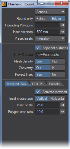
Actions
- Activate - you must either select Activate or click on a Modeler viewpoint before Rounder will actually round any edges.
- Reset - select this to set all the controls on the panel back to their previous (ie. the last time Rounder was used) values.
Points/Edges
Select Points if you only want the points of your selected points to be rounded.


Select Edges if you only want the edges defined by your selected points or edges to be rounded.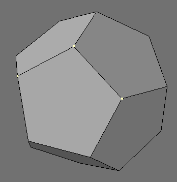

- Rounding polygons - This option sets the number of bevels that will be applied to the edge as illustrated below:
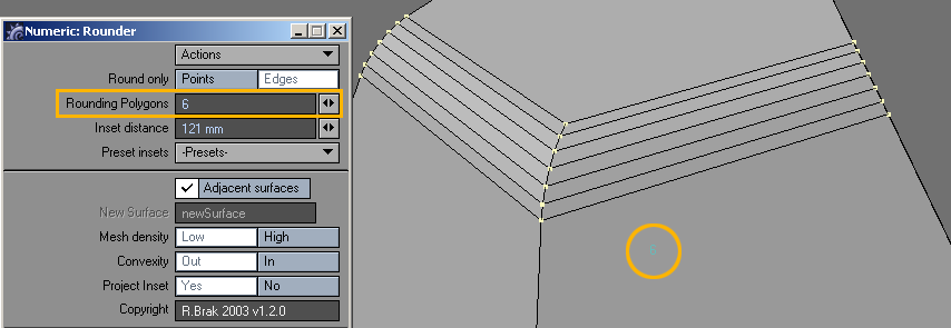
The number of Rounding Polygons setting will appear in the viewport.
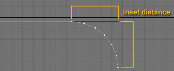
- Inset Distance - illustrated below:
- Inset Presets - This is a popup list of preset inset distances (in the units chosen in Modeler’s Options panel). You can choose which list of presets to use on the Presets Tab.
- Adjacent surfaces - This controls what surface is allocated to the newly created rounding polygons. If this is selected then Rounder will assign the surface to that of the original polygon adjacent to the selected edge as illustrated below:
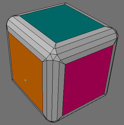
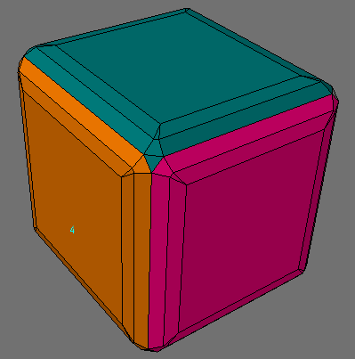
- If it is unchecked, then a new surface is assigned to the new polygons. The name of the new surface is given by the “New Surface” control.
The central polygon on the point corner is adjacent to all the original polygons and hence its surface allocation is intrinsically ambiguous - it is assigned the surface the rounding algorithm first comes across.
- New Surface - All newly created rounding polygons are assigned this surface.
If the Adjacent Surfaces checkbox is selected this option is not available.
- Mesh Density - this determines the type of mesh on rounded points.
- Low - this creates a mesh with a minimum number of polygons.

- High - this creates a mesh on the corners with only quads.
- Convexity - illustrated below.
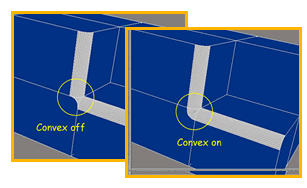
Rounding points will cause them to be “indented” as shown below.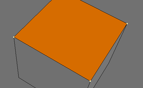
- Project Inset - This button controls how Rounder projects the inset at edges. This is illustrated below:
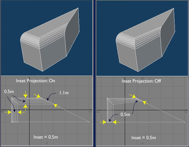
When the projection is on, the width of the rounded edge is equal to the inset distance (0.5 m), but where the rounded edge intersects the side, the width is 1.1 m - which it must be to keep the rounded width constant along the edges. If the inset projection is off, then where the rounded edge intersects the side the width is set equal to the inset distance - this results in a tapering rounded edge. Why have this option? Well, there are situations where the choice of the intersections widths is ambiguous and Rounder has to “guess” what you want. It may not “guess” correctly and in that case it is better to force Rounder to not use projections, as is illustrated for the “wedge” below:

Be aware that Rounder needs a closed mesh to work properly. While it may work on an unclosed mesh, Rounder is likely to crash.
Viewport Tool Tab
- Activate Viewport tool — The Viewport tool allows you to drag the mouse in the viewport to interactively change either the inset distance or the number of rounding polygons by dragging either horizontally or vertically.
- Inset mouse axis — This switch allows you to choose which axis controls the inset distance. If you want to drag horizontally to change the inset distance (and vertically for the number of rounding polygons), then choose Horizontal. Choose Vertical for the converse situation.
- Inset scale — This controls the sensitivity of the mouse dragging when changing the inset distance.
- Polygon step rate — This controls the sensitivity of the mouse dragging when changing the number of polygons.
Open GL Polygon Tab
OGL Polygons? These are additional polygons added to remove OGL display defects. The OGL polygons are in the same plane as the “flat” part polygons adjacent to the rounding polygons. Roughly speaking it stops the OGL renderer smoothing the edge into the bulk of the object and keeps the smoothing to the rounder part of the object.
- Activate OGL polygons — Switch on or off the OGL polygons.
- Inset percent — The size of the polygons is taken as a percentage of the inset distance.
- Surface from — The surface name assigned to the OGL polygons can be:
- Poly — the same as the original polygon (before rounding)
- Edge — the same as that of the new rounding polygons (as determined by the main panel)
- New — the name can be a new name as determined by the next control.
- New Surface — The name of the new surface as chosen by the previous control.
Presets Tab
All the settings on the whole panel are now saved in a file, called RounderConfigs.txt, and reloaded when Modeler is launched. You can “Revert” to the settings in that file or you can revert to the Factory (ie in-built) settings.
You can assign up to three different inset preset files to the three “File” boxes. This allows quick switching between different sets of inset presets - or you can use the default (in-built) set.
More detail for the inset preset files:
1. You need to create inset preset files. You can create the file using a text editor with one number per line (with no units). Create as many files as you like (eg one for mm steps, one for m steps) etc.
2. Click on one of the Preset Inset File numbers (eg “File 1”), then click on the Change File button.
3. Then navigate to one of your inset preset files and select it.
4. All the inset presets are now loaded in and should appear in the inset preset pop-up.
5. Repeat (if desired) for the other two cases.
6. Now, each time you click on a Preset Inset File number, all the preset insets in the associated file are loaded.
- Preset Inset File - Select one of the four possible inset files to use with the Inset Presets pop-up menu on the main panel. File 1, File 2 and File 3 are the three presets files, while Def is the default built-in set of inset presets.
- File 1 — The name of the File 1 inset preset file is displayed here.
- File 2 — The name of the File 2 inset preset file is displayed here.
- File 3 — The name of the File 3 inset preset file is displayed here.
- Change file - This button enables you to navigate to a text file containing a list of inset presets. First select which of the three files, File 1, File 2 or File 3 in the Preset InsetFile row on controls, then click the Change File button and navigate to your preset inset file.
- Revert Settings — Click on this button to change all the settings in the whole panel to those saved in the “RounderConfi gs.txt” file.
NOTE: All the settings of the entire panel are saved to the “RounderConfi gs.txt” file whenever you quit Modeler. - Factory Settings — Click this button to reset all the settings on the panel to the default built-in settings.