Layout OpenGL Options
Display Characteristic Settings
The Show Motion Paths option toggles the visibility of the motion path and keyframes for the current active item in Layout.
A motion path looks like a line with small white (+) symbols at each keyframe. Motion paths are subdivided into smaller segments corresponding to the number of frames between keyframes. With Show Motion Paths active for an object that is stationary during an animation, the graph will display a single keyframe symbol only, indicating that this is its only keyframe position.
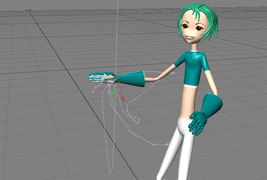
Motion Path for the Right Hand Bone
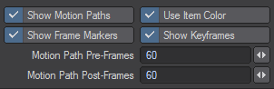
You have the ability to set the quantity of frames shown before the current frame and after it using the Motion Path Pre- and Post- fields. The setting defaults to 60 to match previous versions of LightWave. Other changes in this area of the GL tab of Preferences are:
- Use Item Color - If checked, Motion Paths will be drawn using the item color (defaults to on).
- Show Frame Markers - If checked, Motion Path Frame Markers will be drawn (defaults to on).
- Show Keyframes - If checked, Motion Path Keyframes will be drawn (defaults to on).
Be aware that Layout evaluates to whatever length the motion paths are, so the longer the paths are, the more they will impact performance.
Show Handles
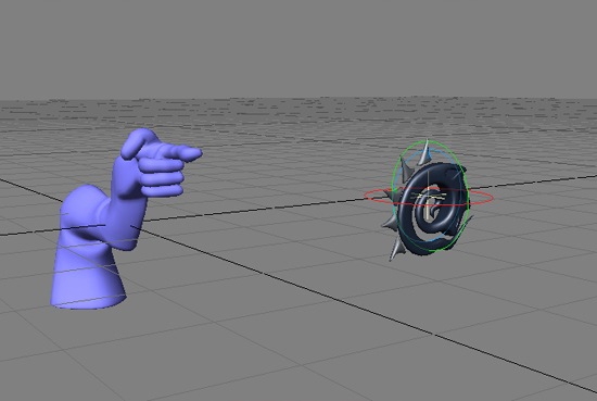
The Show Handles option will display reference handles for the current item when you are moving, rotating, or stretching. These are based on the item’s local axes at its pivot point.
Show IK Chains
The Show IK Chains option will display a solid line for the IK chain and a dotted line for the direction of the item reaching for the goal object.
Show Target Lines
The Show Target Lines option turns on/off the line that connects between an item being targeted and the item targeting it.
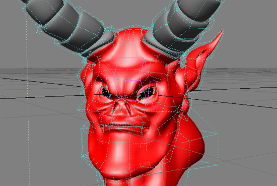
Show SubPatch Cages
When using SubPatch objects, you may want to see the SubPatch cage. Activate Show SubPatch Cages, if this is the case.
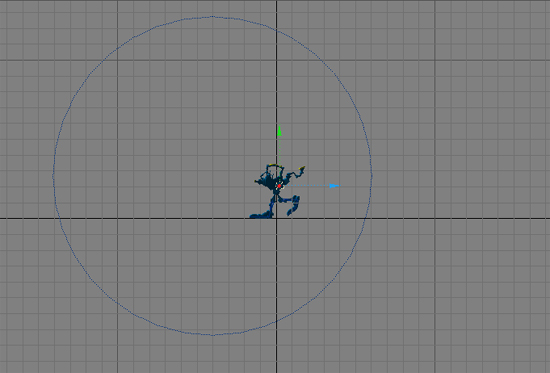
Show Fog Circles
When you want to see the extent of your fog’s Max Distance and Min Distance on the Volumetrics Tab of the Effects Panel (Scene > Effects > Volumetrics), activate the Show Fog Circles option and use one of the orthogonal views. You will see circles representing the two fog radiuses, a result of the minimum and maximum fog values. Just as the backdrop gradient sphere is centered about the camera, so is fog.
If you activate fog and the Show Fog Circles option, but do not see the indicator, check for the following factors:
- Verify that Fog Type on the Volumetrics Tab of the Effects Panel is not set to Off.
- Verify that you are using an orthogonal view.
- Verify that you should be able to see the fog circles. Are you too close or too far from the camera for the circles to be visible? Use the grid as a guide. Also, is the Overlay color too similar to the object color? Try changing to a different display mode, or try changing the Overlay color (discussed below).
Show Spline Targets
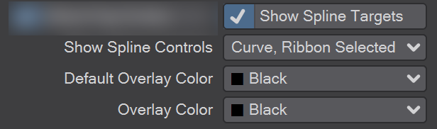
The controls in this section of the GL tab of the Options panel refer to the Spline Control tool.
Overlay Color
The color of the overlays for the field chart, limited region, fog circles, and so on, can be set to any of the standard wireframe colors using the Overlay Color pop-up menu. Setting the Default Overlay Color is saved in preferences. Setting the Overlay Color is not persistent.
Shaded Display Options
The following options affect the shaded OpenGL display characteristics.
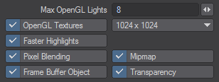
Max OpenGL Lights
Enter the maximum number of light sources you want used in the OpenGL display. This lets you see their your lights’ effect right in the viewport in real-time. It is normally set at 8 since most graphics cards have this as a limit. Professional cards can sometime have more OpenGL lights. The number of OpenGL lights set does not affect renders.
OpenGL Textures
Activate to show image-mapped textures (not procedural) in the viewports. Use the Texture Size pop-up menu to select the pixel resolution (e.g., 1024 x 1024). Lower settings will update faster and use fewer system resources, but go all the way to 16384.
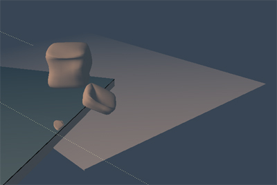
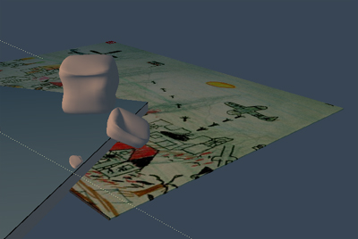
Left: OpenGL Textures Off, Right: OpenGL Textures On
Usually the first Color or Diffuse image map layer is shown in the Texture Mode viewports. Enable Show Texture Editor Layer to show the Texture Editor’s current layer instead, if applicable...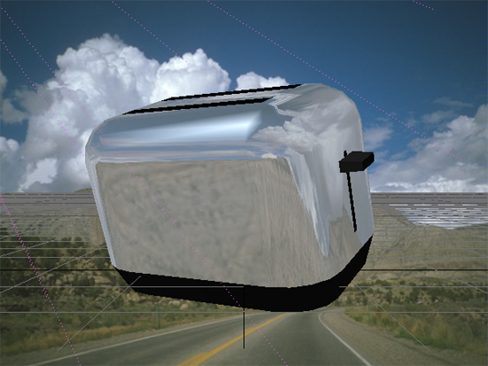
Reflection Mapping will only be visible when the surface Reflection value is greater than 50 percent.
Faster Highlights
The Faster Highlights option makes the display of (specular) highlights faster, but less accurate. Note that the difference may not always be visible and will vary depending on circumstances.
Pixel Blending
This OpenGL option will activate a smoothing display function.
MipMap
Mipmapping is similar to what is used in today’s games to avoid graininess of textures in a distance or at a flat angle. Basically lower- res versions of the texture are generated in realtime and blended in. This feature is supported in hardware by most of today’s graphics cards. This feature also works if Mutitexturing is turned off. Please note however that due to the nature of this filtering method, low-resolution textures may appear a bit blurry.
Transparency
The OpenGL Transparency option activates a surface transparency feature in viewports. This lets you see through transparent surfaces in shaded viewports. (Of course, this is only an approximation of your actual rendered result.) This setting also controls Modeler’s display of transparent surfaces, if the Hub is running. Modeler will remember the last used setting, if you aren’t using the Hub.
OpenGL Options Breakdown
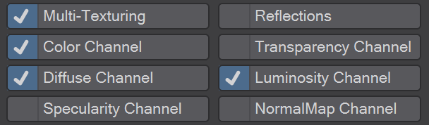
Multi-Texturing
Multi-texturing means multiple textures layers per polygon in OpenGL. Depending on the settings that you activate (see below), the following combinations of texture layers are possible:
- Two color-layers with one diffuse-layer, one luminosity-layer and one reflection map (5 textures/polygon).
One color-layer with one transparency-layer and one reflection map (3 textures/polygon).
Multitexturing is made to work with graphics-cards with at least two texture memory units.
Reflections
This OpenGL option lets you see the effects of image-mapped reflections (not ray-traced) in a Layout window.
Color Channel
For the display of textures in the Color Channel if Multi-texturing is on.
Transparency Channel
For the display of textures in the Transparency Channel if Multi-texturing is on.
Diffuse Channel
For the display of textures in the Diffuse Channel if Multi-texturing is on.
Luminosity Channel
For the display of textures in the Luminosity Channel if Multi-texturing is on.
Specularity Channel
Shows image maps and texture for the Specularity channel.
NormalMap Channel
Shows applied Normal Maps.
Shading Method
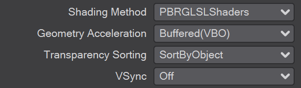
In the Shading Method dropdown you have the choice between Multi-Texture, GLSL Shaders and PBRGLSL Shaders. We have detailed how Multi-texturing works just above.
PBRGLSL Shaders
Advanced GLSL shaders emulating the materials in the Software Renderer/VPR closely. Although shadows are not catered for, the fidelity of these shaders is much closer to VPR render equivalents. Cel shaded textures and reflections are also duplicated in OpenGL.
New to 2019
The PBRGLSL shader is more demanding on hardware than GLSLShaders and lower-end GPUs may struggle.
GLSLShaders
GLSL OpenGL Hardware Shading supports the OpenGL 2.0 hardware shader technology in video cards to provide very close approximations of render functions in the viewport displays. Light falloff, surface blending, gradients, and many procedurals can now be displayed in the OpenGL viewports in Layout when GLSL HW Shading is turned on.
New to 2018
Two new channels have been added to the visibility options for Layout. The Specularity Channel will show image maps and texture for the Specularity channel and NormalMap Channel will show applied Normal Maps. CGFX shading was removed in 2018, but these two perform many of the same functions and are more general.

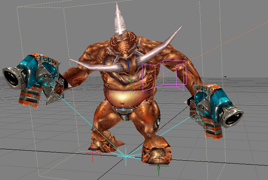
OpenGL view with Normal map, Specularity and Depth of Field - this display is not VPR
Geometry Acceleration
Determines how the graphics card displays OpenGL. Streaming renders the mesh immediately to screen, using the lowest amount of memory at the cost of speed. Buffered(VBO) will attempt to store the geometry in graphics card memory, allowing for the highest speed, at the cost of memory. In cases where the mesh or shading changes with every frame no caching is possible, a fallback to the Streaming method will result, for example with animated meshes and reflection maps. Smooth shaded geometry will benefit the most from the Buffered(VBO) mode. If the mesh is buffered in graphics card memory the performance you will get as much performance as your graphics card can give you.
Transparency Sorting
It’s usually fastest to leave this as it is, on SortbyObject. However, if you have a large quantity of surfaces with varying degrees of transparency, for accuracy you may prefer to choose SortbyPolygon. AlphaClipping is the fastest of the three methods but really is clipping. Anything less than 100% transparency shows as solid.
VSync
There are three options and again, leaving this setting to Always On should be the best choice in most cases. If your scene is extremely heavy setting it to Off or Only When Playing might give you a speed advantage when setting up the scene.