Spline Control

LightWave can animate using a virtual spline. LightWave users familiar with the Animation Path Wind tool will feel instantly at home with the way that Spline Control is set up and users transitioning from other 3D software will appreciate the flexibility LightWave brings with its virtual splines.
How to Create the Spline
In order to use this tool, the user must create a virtual spline. This is not a new idea for LightWave, since Animation Path Wind used a virtual spline back in LightWave v9. To create a virtual spline, the user must parent two or more items to a parent item. These child items must also meet the following two conditions: they must be marked “active” with checkmarks in the Scene Editor, and they must have no children of their own. Then that parent item must be referenced by the Spline Control setting of at least one other item in the scene. The parent item represents the container for the spline, and the child objects will represent the nodes for that spline.
Bones and Joints can serve as the child items that define the nodes of a virtual spline. Unlike Objects, Lights and Cameras, however, Bones and Joints default to “inactive” (unchecked in the Scene Editor) when first added to a scene. Because Spline Control ignores inactive items in a Spline Control Item’s hierarchy, Bones and Joints will not appear to work until they are activated in the Scene Editor. In addition, two or more of these active Bone/Joint items must have no children of their own in order for these items to count as the nodes of a virtual spline.
When the root of a hierarchy is presented as a Spline Item, Spline Control considers all of the items on that hierarchy that have no children of their own. This means that the user can parent items together in order to insert puppet controls between the nodes of the virtual spline and the Spline Item that forms the root of the hierarchy. An example of how Spline Control only considers “leaf-children” can be found in the “01_Learning” section of the example content.
To align the rotations of a virtual spline’s nodes to itself, change the Heading Controller, Pitch Controller and/or Bank Controller to “Spline Control.” When no specific spline item is specified, the nodes will align their rotations to the spline that they themselves describe.
Getting Started with Spline Control
- Start with an empty scene.
- Add a null object to the scene, and name it “Spline”.
- Add two more null objects to the scene, and give them each the name, “node”.
- Parent the two node null objects to the Spline null object.
- Move node (1) 2 m further away on the Z axis, and node (2) 4 m. Select the Camera and use the keyboard shortcut M to open up its Motion panel.
- Spline Control is near the Parent and Target settings. Change this Spline Control setting to Spline.
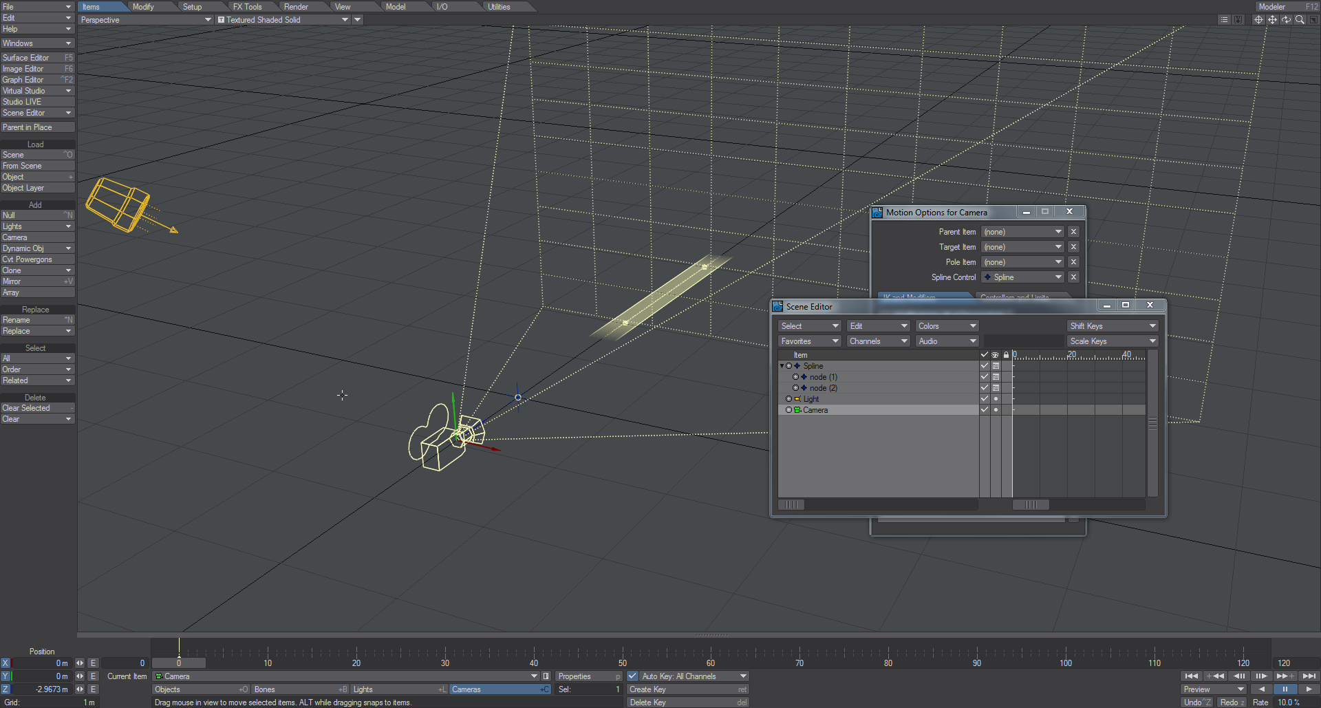
You have just created a virtual spline that can override the Position and Rotation channels of the Camera. A ribbon will be drawn through the two nodes to show you the path of the spline.
- Now, select the second node and clone it twice.
- Move these clones away from the original null object and from each other. You have just added two more control points to this spline.
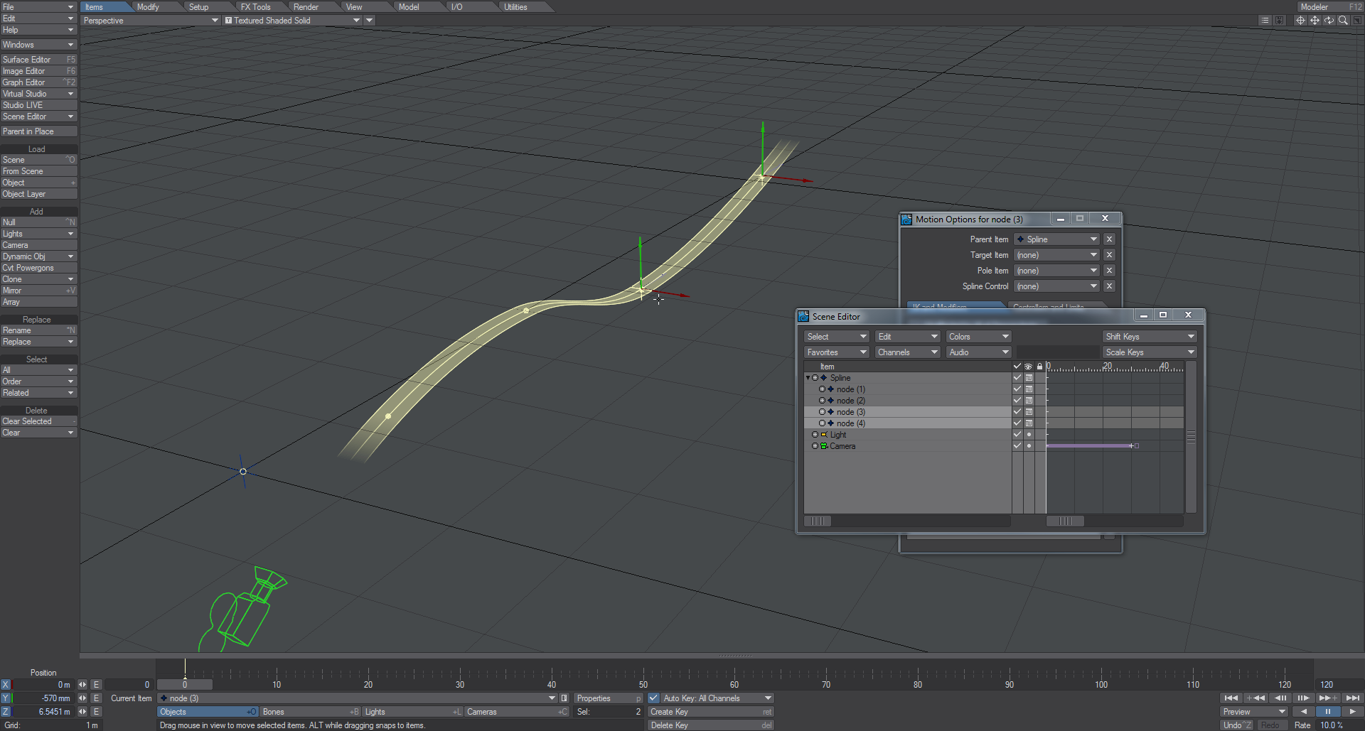
- Select the Camera (which still refers to the “Spline” null as its Spline Control). While under the influence of Spline Control, the Z position of the Camera represents the distance traveled along the spline. In the lower-left-hand corner of Layout, enter XYZ values of 0 m, 0 m, 0 m for the Position data.
- Scrub to frame 30, enter a Z value of 6 m for the Position data and make a keyframe. If you play from 0 you will see the Camera will travel 6 m along the spline. The values shown in the lower-left-hand corner will be the XYZ values applied by Spline Control. These are the same XYZ values that will be reported to tools that reference motion data, such as Same as Item.
- If the Camera banks unexpectedly, there are two ways to correct it. The first way: Select the Camera. Tap M to bring up the Motion Options panel. Go to the Controllers and Limits tab and go to the Rotation tab. Change Bank Controller from Spline Control to Keyframes.
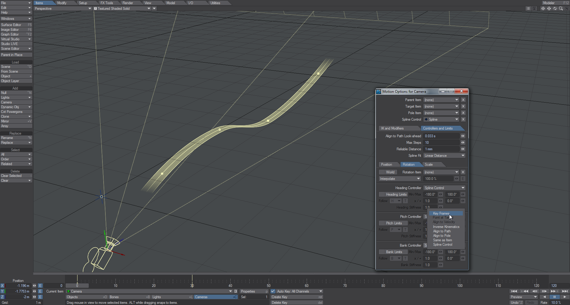
The user can then keyframe the bank by hand. However, the alternate way is to try to correct the spline path itself:
- Select each node (the child objects that define the nodes of the Spline) and rotate their Heading to align them with the path of the spline.
- This can help reduce unexpected banking errors as the camera moves along the spline, but it may not be as reliable as disabling Spline Control for the Bank Controller.
Note that you can also use Spline Control with Instancing for interesting animation possibilities. The process is described in the Instancing reference. Genoma also adds Spline Control features described here.
 Going Further
Included with the LightWave content are a number of scenes that demonstrate very well what Spline Control can do, with helping text.
Modeler Spline for Spline Control
You can now use splines created in Modeler as Spline Control splines in Layout. Splines are created in Modeler by laying down points and using Ctrl-P to create a spline rather than P to create a polygon. Once saved and sent to Layout, they can be used as a Spline Control spline simply by selecting the items to be on the spline and choosing the Modeler spline object as their control.
If your spline is complex, it can be laborious to create it in one go. If you need to create a spline in parts, selecting the parts and using Merge Polys (Shift-Z) will join the splines.
How to View the Spline
You have the choice of how you would like the spline displayed in the GL section of the Options panel. Here are the choices:
When the Spline is not selected and the Curve or Ribbon options are chosen it will be drawn in the object color for the Spline object. If the Spline is selected it will appear in the normal LightWave yellow as shown in 3 and 6.
There is an additional option, Show Spline Targets. This links a dotted line back from each node to the parent of the whole spline no matter how deep inside the hierarchy it is.
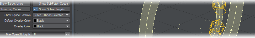
Show Spline Targets and Curve, Ribbon Selected options chosen (Spline is selected)
How to Tweak the Spline
Rotating the Heading and Bank of each node on the virtual spline will affect the bend and twist of the spline.
How to Activate/Deactivate Spline Control on a Per-Channel Basis
Spline Control affects Position and Rotation channels by default. However, these can be disabled on a per-channel basis by going to the Controllers and Limits tab of the Motion Options panel and changing Controller options in the Position/Rotation tabs from Spline Control to Key Frames.
Open vs Closed Splines

A spline is open by default. To create a closed-loop spline, select the spline item - that being referenced as the Spline Control of another item. Type m to access the Motion Options panel, and go to Controllers and Limits. Activate the Closed Spline checkbox to close the spline.
The Z Position Represents the Distance Traveled Along the Spline
Animate the Z Position of an item driven by Spline Control to push that item up or down the spline.
Item Chains
A chain of items refers to a hierarchy where each item is the child of the next item. An example of an item chain would be a linked chain of train cars, where the caboose is parented to a boxcar, which in turn is parented to the engine. Another example would be the bone chain that represents the spine of a snake or the spine of a Chinese dragon.
To apply Spline Control to an item chain, select all members of the item chain, type m to access the Motion Options panel, and change the Spline Control item from (none) to the parent item representing the virtual spline. All items in the chain will conform to the spline. Animating the Z Position of the root item in the item chain will push/pull the entire item chain along the spline.
You do not have to apply Spline Control to an entire hierarchy. For a Chinese dragon, apply Spline Control only to the spine bones of the dragon and not to the leg and arm chains. That way you can use Spline Control to animate the spine of the dragon and other means (such as FK or IK) to animate the legs, arms, head and jaw of the dragon.
Animate the Nodes of the Spline to Animate an Item Chain
Animate the nodes of the spline to change the shape of the spline. This, in turn, will change the shape of the item chain that conforms to the spline.
Curve to Spline
Creating splines in Layout is fine when you are only using a few nulls to make your spline, but if you need hundreds to make a complicated path then creating them all with nulls in Layout could be a laborious process. A tool has been added to Layout to streamline the creation of such splines. To use it, create a curve in Modeler using whatever method you like (Add Points, then Make Open Curve on the Create tab; import an EPS using the Spline Curves option, etc.), save it and send it to Layout. In Layout, go to the Setup tab and in the Edit group use Curve to Spline. If you have multiple splines in your object you need to split them over several layers since Curve to Spline only works on the first spline in a layer. Rather than using nulls, the controls in the spline in Layout are created using bones (specifically Joints), which has two advantages - the Layout object list isn’t filled with nulls needlessly, joints automatically have a pleasing “control” shape and can be sized in the viewport using the Options > Display > Handles & Icons settings.
Export Spline
Export Spline is a tool in Setup > Edit to convert Spline Control splines in Layout into Modeler curve objects. Simply select the head of a spline object and hit Export Spline and the entire spline will be saved as an LWO that can be further edited in Modeler, then reimported to Layout using Curve to Spline again. When reimporting like this, Curve to Spline will note that the spline has already been used and intelligently update node positions and quantities as needed rather than generating a new spline.