Modeler General Options
(default keyboard shortcut O)
You can access the General Options Panel by choosing Edit > General Options.
General Tab
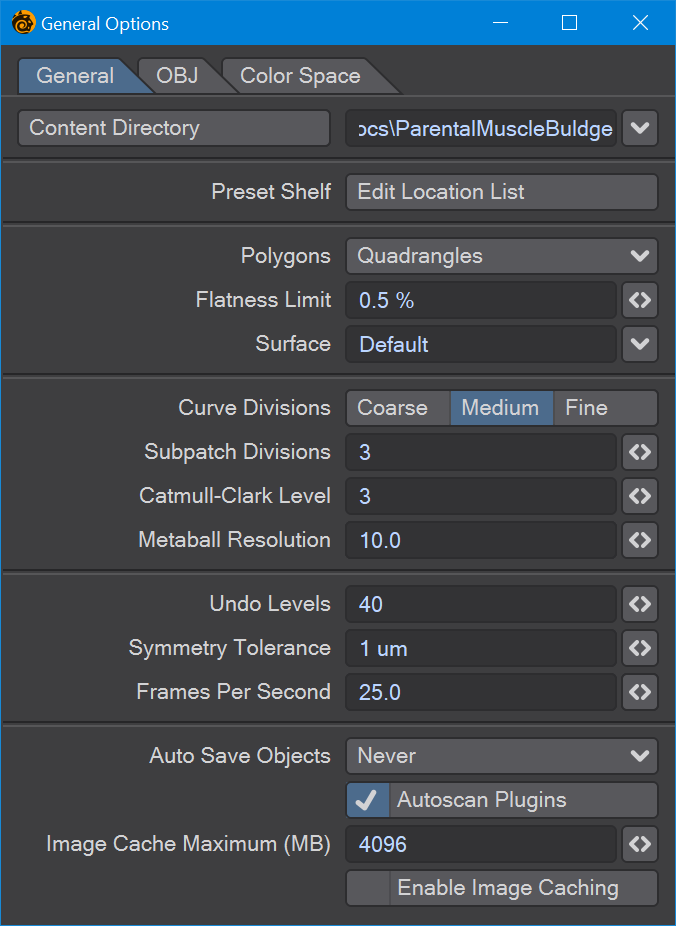
- Content Directory - The Content Directory is a central file path for loading objects, images, and scenes. Note that this setting is shared by all LightWave applications.
- Default Polygon Type - Some operations in Modeler create many polygons in one operation. As such, the computer must decide whether to generate triangles (three-point polygons) or quadrangles (four-point polygons), depending on the shape’s requirements.
To force the computer to use Triangles or Quadrangles, select either for the Polygon setting. Choose Automatic to let the computer create the most appropriate polygon type for each given operation.
- Flatness Limit - The Flatness Limit setting determines whether Modeler regards a polygon as planar or not. Note that a non-flat polygon considered planar according to this setting can still cause rendering errors.
All polygons must have a surface name. When geometry is created, polygons are given the default surface name of Default. You can change the default name by changing the Surface field. This will affect only geometry created from that point on, however. Use the pop-up to the right of the field to select from existing surface names.
- Curve Divisions - The Curve Divisions setting determines how smoothly a curve (e.g., spline curves, text, etc.) should be interpolated. The finer the setting, the greater the number of polygons used, and the smoother the resulting curve division.
- SubPatch Divisions - When a SubPatch object is frozen with the Freeze command ( Ctrl D), it is converted into a polygonal object. The Patch Division setting determines the level of detail used in the resulting object. The number entered in the Patch Division field must be 1 or greater and is restricted to whole numbers.
The number of polygons per SubPatch surface will be equal to the square of the Patch Division number. For example, if set to 4, each SubPatch surface will be converted into 16 polygons arranged in a 4 by 4 array. A setting of 2 would result in 4 polygons arranged in a 2 by 2 array. For Catmull-Clark patches, every level of Catmull-Clark subdivision quadruples the number of polygons.
The higher the setting, the higher the number of polygons used. Because of LightWave’s surface smoothing capabilities, you can often get away with a setting of 2 and sometimes even 1, which will keep the polygon count of your objects to a minimum.
- Metaball Resolution - This setting determines the amount of detail used to display metaballs.
- Symmetry Tolerance - Sets the amount matching elements can differ on opposite sides of the symmetry for symmetry to work.
 Frames Per Second - Added to 2019 for nodeflows that have a time component, envelopes or nodes like Time.
- Image Cache Maximum - If enabled, sets the amount of caching available for images in megabytes.
OBJ Tab
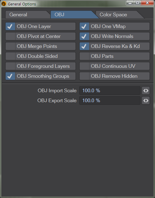
The OBJ tab contains options for importing and exporting OBJ file objects.
- OBJ One Layer - imports the object as a single layer
- OBJ One VMap - imports the object with a single vertex map
- OBJ Pivot at Center - creates the pivot of the object at the center of the object
- OBJ Write Normals - writes the normals associated with the object when saved
- OBJ Merge Points - merges points sharing the same space
- OBJ Reverse Ka & Kd - Reverses Ambient Occlusion and Diffuse channels
- OBJ Double Sided - Creates double-sided geometry
- OBJ Parts - Keeps LightWave Part Polygon tags
- OBJ Foreground Layers - Only saves layers marked as foreground to OBJ
- OBJ Continuous UV - UVs have shared points rather than duplicated
- OBJ Smoothing Groups - Supports the new Smoothing Groups system
- OBJ Remove Hidden - Polygons that are hidden will not be exported (Hiding layers does not have any effect)
- OBJ Import Scale - sets the scale of an object when it is imported
- OBJ Export Scale - sets the scale of the object when it is exported
Color Space Tab
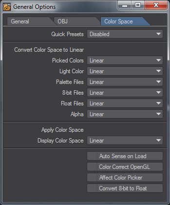
Color space conversion is performed in four places in LightWave.
- On loading, an image can be converted from its native color space format to linear.
- When sent to the Image Viewer, an image can be converted from linear to another color space.
- When saved from the renderer, an image can be converted from linear to another color space.
- When picked from the Color Picker, a color can be converted from and then to linear color space.
The color space defaults are set up on the Layout Preferences panel.When an option is selected in the pop-up it becomes the current item for that selection.
Color tables are added to the selections, as if they were built-in.
A color table can be loaded by using Load Table from the pop-up. The color tablesare stored in the project directory, in a directory called Color Tables.
In the Image Editor, there is a check box, Treat as Alpha. This means use the alpha channel from the Preferences Default setting, not the alpha channel from the color space in the Image Editor. This is an override on the alpha color space selected in the Image Editor.
One can set the color correction for the Viewer files with palettes, 8-bit files, floating point files, alpha channel and the color picker from the preference default panel and the Modeler General Options panel.
When an image is loaded, if the file setting for that image is set to default, then an attempt is made to look at the metadata setting for that image. If the metadata settings have the color space the image was saved in, then it is used. For example, jpegs have metadata setting for sRGB and Adobe 1998 linear format.
The built-in color spaces are:
- Linear, LightWave linear color space.
- sRGB, Standard RGB color space.
- rec709, BT.709, HDTV
- Cineon, Eastman Kodak Co.
The color lookup tables come in two formats:
- LightWave color table format.
- 3D LUT format.
LightWave color table format is as follows:
Code:
EGA
17, -0.5, 1.5
; Convert on load.
-0.5, -0.5, -0.5, -0.5
-0.375, -0.375, -0.375, -0.375
-0.25, -0.25, -0.25, -0.25
-0.125, -0.125, -0.125, -0.125
0.0, 0.0, 0.0, 0.0
0.125, 0.125, 0.125, 0.125
0.25, 0.25, 0.25, 0.25
0.375, 0.375, 0.375, 0.375
0.5, 0.5, 0.5, 0.5
0.625, 0.625, 0.625, 0.625
0.75, 0.75, 0.75, 0.75
0.875, 0.875, 0.875, 0.875
1.0, 1.0, 1.0, 1.0
1.125, 1.125, 1.125, 1.125
1.25, 1.25, 1.25, 1.25
1.375, 1.375, 1.375, 1.375
1.5, 1.5, 1.5, 1.5
; Convert on save.
-0.5, -0.5, -0.5, -0.5
-0.375, -0.375, -0.375, -0.375
-0.25, -0.25, -0.25, -0.25
-0.125, -0.125, -0.125, -0.125
0.0, 0.0, 0.0, 0.0
0.125, 0.125, 0.125, 0.125
0.25, 0.25, 0.25, 0.25
0.375, 0.375, 0.375, 0.375
0.5, 0.5, 0.5, 0.5
0.625, 0.625, 0.625, 0.625
0.75, 0.75, 0.75, 0.75
0.875, 0.875, 0.875, 0.875
1.0, 1.0, 1.0, 1.0
1.125, 1.125, 1.125, 1.125
1.25, 1.25, 1.25, 1.25
1.375, 1.375, 1.375, 1.375
1.5, 1.5, 1.5, 1.5
Where:
EGA is the name of the color space that appears in the pop-up.
17 is the number of entries in the color table.
-0.5 is the lower range of the look-up table ( black ).
1.5 is the upper range of the look-up table ( white ).
-0.5, -0.5, -0.5, -0.5 are the rgba values for the table entry.
Blank lines and lines beginning with comments, are skipped over.
3D LUT format tables are read in and a reverse lookup table is made. The name of the color space is the name of the file on the pop-up.
Auto Sense on Load detects the Color Space settings and uses those when a scene is loaded.
Color Correct OpenGL will color correct the OpenGL viewports.