Item Info
This group contains nodes to control or be controlled by scene items. Those items could be Objects, Lights, Cameras or control surfaces like 3D mice. If you need to base your surface on the position or rotation of one of these items you’ll need these nodes.
Bone ID
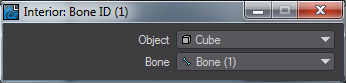
Select the object and appropriate bone and the node outputs the bone state.
Bone Info
Outputs bone item ID, and the item ID of the owning object, of the bone selected in its settings.
Camera
This is a standalone node that provides access to a camera’s current settings. Any of the cameras in the current scene may be selected by double-clicking on the node. The outputs are then derived from the settings for the selected camera.
Outputs
- Zoom Factor (Scalar) - The Zoom Factor output is taken from the zoom factor as defined for the selected camera.
- Focal Length (Scalar) - The Focal Length output is taken from the lens focal length as defined for the selected camera.
- Focal Distance (Scalar) - This value is taken from the DOF tab Focal Distance value for the current frame.
- Lens F-Stop (Scalar) - This value is taken from the DOF tab Focal Distance value for the current frame.
- Blur Length (Scalar) - The Blur Length output is taken from the blur length as defined for the selected camera.
- Horizontal FOV (Scalar) - The Horizontal FOV output is taken from the horizontal FOV as defined for the selected camera.
- Vertical FOV (Scalar) - The Vertical FOV output is taken from the vertical FOV as defined for the selected camera.
- Width (Integer) - The Width output is taken from the image width as defined for the selected camera.
- Height (Integer) - The Height output is taken from the image height as defined for the selected camera.
- Pixel Width (Scalar) - The Pixel Width output is taken from the pixel width ratio as defined for the selected camera.
- Eye Separation (Scalar) - The Eye Separation output is taken from the eye separation as defined for the selected camera when stereoscopic rendering is enabled.
Edit Panel
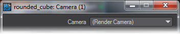
The Render Camera is the one used on a specific frame for rendering but you can also choose other scene cameras if you want to base the surface on a camera positioned differently.
Device
The Device node initially appears with no connections at all. You will need to double-click on it to open this requester:
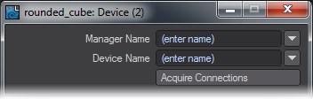
You can either type over the (enter name) text or select from the dropdown menu. If your devices are not found you may need to visit the Virtual Studio > Device Manager window and make sure the device type you wish to use is enabled. Manager Names choices are:
- HID - The Microsoft Human Interface Device standard is home to many mice and other devices and is your first port of call
- Intersense - A manufacturer of high-end virtual cameras
- Kinect for Windows - to use the Kinect device for motion capture or surfacing
- PS3 Move.Me - A system to use the PlayStation 3 Eye Toy camera
Device Name can be a vast list of devices if HID is chosen as the Manager type. Once you have chosen a Manager and Device, the Device icon will look like this:

You can now connect the outputs from this device into your network. Most devices aren’t very useful for creating a surface, this one is more useful for the Virtual Studio part of Layout. However, they are still available since The Control Booth panel part of Virtual Studio does have access to the button presses for Virtual Studio devices. An LScript or Python script or Generic plugin can be assigned to the button press. Arguments to pass to the command can be specified in the Control Booth as well.
Dynamics Part Info
For use with Bullet Dynamics object, this node enables control over the individual elements of a Parts object. This node has no panel just connections.
Inputs are the Item ID of the dynamics body, and either the Part Number or the Polygon Index. If the part number is connected it will use that part, otherwise it will use the polygon index to figure out the part that the polygon is in. If the item or polygon index are not connected, the node will get them from the evaluation context.
Outputs are:
- Part Number - the index of the part
- Internal Polygon - 1 if the polygon is currently internal, 0 otherwise
- Part World Position/Right/Up/Forward/Rotation - current transform of the part in world coordinates
For parts objects, internal polygons are those that join two parts together. When the parts break those polygon stop being internal and become part of the outer surface.
If the object is transparent, like glass, you probably don't want internal polygons to show until the glass fractures. You can achieve that in a nodal shader by hooking the Internal Polygon output to the Clip input of the Surface node. Or alternatively use it to switch between two different materials or material properties.
Another use of the Dynamics Part Info node is in a nodal motion setup to track the position and orientation of a particular dynamic part. Hook up an Item ID node to the Item ID input to select the dynamics item, an Integer constant node to the part number to select the part, and use the part position and rotation outputs to get the motion.
Note that the position and orientation is for the center of mass of the part, not the pivot of the item.
Note that this node works from Frame 1 of a dynamics simulation. At Frame 0 it is not yet activated
Item ID
Double-clicking on this node will open a window with all scene items in a dropdown list. The single integer output gives the item's ID.
Item Info
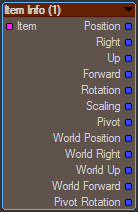
This node can report on an item in a scene: Object, Light or Camera (for Bones, use the Bone Info node). It gives details the item’s position, rotation and other vector information.
New to 2018
Item Info now has an Item ID input rather than just double-clicking on the node to choose a scene item.
Edit Panel
Light Info
This is a standalone node that provides access to a light’s current settings. Any of the lights in the current scene may be selected by double clicking on the node. The outputs are then derived from the settings for the selected light.
Outputs
- Color (Color) - The Color output is taken from the color selected for the light.
- Range (Scalar) - This is the value set when Falloff is engaged. If no falloff has been used, the value is 1.0.
- Intensity (Scalar) - Based on the Intensity set in Light Properties.
- Shadow Color (Color) - Taken from the setting on the Shadow tab.
- Direction (Vector) - For a directional light, like the Dome or Area, this is the vector for the direction. For a Point or Spherical light this is 0, 0, 0.
Mesh Info
Input item ID of an object and a point index, outputs info about that point.
Mesh Part
Gets information about the mesh part the current vertex is in
Inputs
- Object - mesh item to get part info from (defaults to the object being evaluated)
Outputs:
- Part Index (Integer) - index number of part
- Part Center (Vector) - center position of the part
- Part Box Min, Part Box Max (Vector) - the bounding box of the part
- Part Normal (Vector) - normal of the first polygon of the part
Mesh Tangent
Input item ID of an object and a point index, outputs the tangent, normal, and binormal directions at that point. Tangent is based on texture coordinate direction specified in the node's settings.
Mesh Vertex Find
Input item ID of an object and a position in object coordinates, outputs the point index of the vertex matching that position in either base or final deformed coordinates depending on the node's settings.
Studio Trait
This node is intended for use with LightWave’s Virtual Studio. It can be made use of in the Surface Editor, but similar outputs are available without the setup needed to use a Studio Trait node. If you would still like to use it, you will need to choose your scene item, go into its Motion Options and add the Virtual Studio Trait modifier. At that point, it becomes visible to the Studio Trait node and can be selected. You will get vector outputs of Position, Rotation and Scale.
Time
Information about the current scene time and frame
Outputs:
- Time (Scalar) - The current frame time
- Frame (Integer) - The current frame
- Blurred Time (Scalar) - The current frame time plus any offset due to motion blur
- Blur Fraction (Scalar) - The motion blur fraction of the current evaluation (0 == start of blur, 1 == end of blur)
- Frame Start (Scalar) - Start time of the current frame
- Frame Duration (Scalar) - Integration time of the current frame (i.e. the motion blur duration)
- Frame Stride (Scalar) - Time between the start of this frame and the next
- FPS (Scalar) - Scene Frames per second setting