Gradient
The nodes in this group are all related to the gradient in the normal Surface Editor and present two different ways of creating gradients.
Tools
Incidence
The Incidence node derives the angle between the current hit point and the camera. It may also be used to derive the angle between the current hit point and any arbitrary vector. When a polygon is completely facing the camera, the output will be 1.0. When it is parallel to the camera, it will have what's called a glancing angle and the output will be 0.0.
- Vector - By default, the Result output is defined as the angle between the viewing vector and the normal at the current hit point. However, any vector can be used to replace the viewing vector. For example, you may wish to drive the Vector input from a Make Vector node and define the input vector as 0.0, 1.0, and 0.0 for X, Y and Z respectively. This means that the Result output will the angle between hit point and a vector defined as being straight up. The output will then appear as a “snow cap” for the current object.
- Normal - The Normal input allows the angle to be perturbed. This input can be driven with any normal and is perturbed by the direction of that normal for the current hit point.
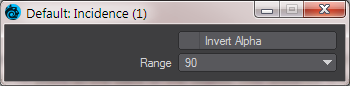
Incidence outputs a Scalar of the angle generated by the Vector input and Normal input. Double-clicking on the node presents the possibility to Invert the output (or you could insert an Invert node). You can make the range over 90 or 180 degrees. This is to cover situations where highly reflective objects can sometimes have reflections from behind the outside curve of the object - think of a chrome ball where highly-lit reflections from the back side can be visible.
Thickness
The Thickness node derives the thickness as defined by the length from the current hit point to the back of the object. This node provides a thickness function by firing a ray from the current hit point to the back of the object. This distance is output as the Length. For this node to function correctly, ray tracing must be enabled by checking anyone of the four ray trace options (i.e. ray trace shadows, transparency, reflection or refraction) in the rendering options. The object must also have the double sided option enabled or all of the polygons correctly aligned so that the rays fired back to determine the thickness have something to hit.
Curve
The Curve gradient node uses a graph editor to create a color gradient. Using red, blue and green color channels, as well as an alpha channel, limitless color gradients are available. The Curve Editor works much like the Graph Editor, you can add/subtract and edit keys and change the type of curve. The Curve Editor has the advantage of being able to tie into the Graph Editor via envelopes to have animated curves.
Inputs
- Bg Color - Can receive colors and patterns from other nodes in the network. Users may also specify a color using the controls found in the Edit Panel for this node.
Specifies the color of the background color layer. - Blending - Can receive input from other nodes in the network or can be specified to by selecting a blending mode from the Blending pull-down menu in the Edit Panel for the node.
For general use specifying the blending mode by using the Blending pull-down menu in the Edit Panel will probably be the most desirable method of use. However, for larger networks where control of the blending modes of many texture nodes simultaneously is needed or when conditional blending is desired then using a node connection to control this value may be advantageous. - Input - The output color and alpha are derived using the gradient based on this input.
Edit Panel

- Bg Color
- Blending Menu
- Input Menu - If nothing is attached to the Input for the Curve node, five choices are presented:
X Coordinate - where the output is interpolated based on the gradient using the object’s X coordinate for the current hit point as the input.
Y Coordinate - where the output is interpolated based on the gradient using the object’s Y coordinate for the current hit point as the input.
Z Coordinate - where the output is interpolated based on the gradient using the objects Z coordinate for the current hit point as the input.
Slope - where the output is interpolated based on the gradient using the angle between the current hit point and the object’s up direction as the input.
Incidence - where the output is interpolated based on the gradient using the angle between the current hit point and the camera’s viewing direction as the input. - Edit Menu - presents these options:
Delete Selected Keys - This function deletes any selected keys.
Undo/Redo - This function will undo or redo a function performed in the curve editor.
Purge Undos - Removes the Undo stack
Select All - Selects all selectable keys in the curve editor
Clear Selection - Clears all selected keys
Invert Selection - Keys that are selected will no longer be selected and keys that are not selected will now be selected
Copy/Cut/Paste - These functions will copy, cut or paste keys in the curve editor
Fit All - The function will fit all keys into the view
Fit Selected - This function will fit the selected keys into the view
Line Antialiasing - This toggle will antialias curves
High Quality Lines - This toggle will change between a quickly-drawn curve and a more accurate one
Show Control Points - Toggles the control handles for the keys - Add Keys will add additional keys to the Curve Editor when the button is activated and you click the LMB on the curve window. Stretch mode will move the keys when activated and you click the LMB. LMB stretches the values (Y), and holding down Ctrl stretches the positions (X).
- Pan and Zoom buttons.
- Value and Position - Specifies the value and position for the selected key. The values can be enveloped.
- Curve Menu - Selects the specific curve type to be used for the selected key.
- Lock CP - Locks the curve control point. Unlocking allows each side of the control point to be edited individually.
- Channels - Selected channels will be highlighted. Multiple channels can be selected at once and the selected channels will receive any editing done by the user.
Gradient
This node allows for either a color or an alpha gradient to be created. This gradient is then interpolated based on the input. The input may come from an external connected source such as a texture node or from one of the user selectable internal sources (e.g. Slope).
Unique Inputs
- Key(n) Color (Color), Key(n) Pos (Scalar), Key(n) Alpha (Scalar) - When the Show Output toggle is engaged for a key, these inputs will appear on the node so you can hook up other nodes to them.
Edit Panel
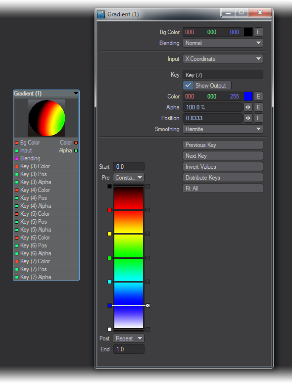
Basic Gradient Creation
In its simplest form, the gradient node allows a color gradient to be created. In the bottom of the edit panel you can see a vertically aligned gradient. The range of the gradient is defined by the start and end values at the top and bottom of the gradient. These can be changed as required for different input ranges. For example, with the thickness you may wish to define a range from 0.0 to 10.0 meters. This can be achieved by editing these boxes.
You can add keys by clicking at the required insertion point on the gradient. Keys may be moved by clicking and dragging its associated square (on the left of each key). A single click on a key’s square will select it. The currently selected key will have its bar turn white.
Keys may be deleted by clicking the X on the right of the bar.
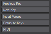
- Previous Key and Next Key - These are for cycling through the keys in a gradient
- Invert Values - inverts (top to bottom) the values on all the keys in the gradient
- Distribute Keys - spreads the keys out evenly between the top and bottom of the gradient
- Fit All - Resizes the gradient so that all keys are visible by changing the End value appropriately
Individual Key Editing
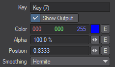
Once the range has been set and keys added, these can be edited individually using the control in the section above the gradient.
The Key text box will display the name of the currently selected key.
- Show Output - this check box allows the currently selected key to be added to the nodal inputs (i.e. the inputs will appear on the node and may then be connected to). When this is enabled Color, Position, and Alpha inputs are added for that key. This allows these parameters to be driven from other nodes so you could, for example, have the color for a key driven by the color output from a texture node.
- Color - allows the color for that key to be defined. The output of the gradient is defined by the color of each key. Each key color can be enveloped and changed over time.
- Alpha - allows the alpha value for that key to be defined. The alpha values primarily define how the current gradient is blended with the Bg Color. The blending is defined by the user controlled Blending input. The different blending modes are covered in the Reference Section on Blending Modes. Again, the alpha values may be enveloped and change over time.
- Position - defines the position of the key on the gradient. For the key to appear on the gradient, the value must be between the start and end values (or equal to one of them). The key positions can be enveloped and changed over time. It is possible to provide a position outside the range of the gradient. This means that the key will not appear on the gradient and may only be selected using the Previous and Next Key selection buttons.
- Smoothing - defines the transition from the current key to the next. By default, this is a blend based on a Hermite curve. However, this also can be Linear for a straight blend, Step for a discrete step, or Bezier for a blend based on a Bezier curve.
Driving the Gradient
The color output is defined by the gradient and some input. The input may be from an external node driving the Input node or from an internally-selected gradient type. Essentially, the gradient provides a look-up table of colors. The input (internal or external) provides a position on the gradient. This gradient then uses the keys to interpolate an output color and alpha based on the input.
With nothing connected to external Input the gradient type may be selected using the Input drop down list. The choices are:
- X Coordinate - where the output is interpolated based on the gradient using the object’s X coordinate for the current hit point as the input.
- Y Coordinate - where the output is interpolated based on the gradient using the object’s Y coordinate for the current hit point as the input.
- Z Coordinate - where the output is interpolated based on the gradient using the object’s Z coordinate for the current hit point as the input.
- Slope - where the output is interpolated based on the gradient using the angle between the current hit point and the camera’s up direction as the input.
- Incidence - where the output is interpolated based on the gradient using the angle between the current hit point and the camera’s viewing direction as the input.When the external Input is connected to another node, these options become unavailable, and then the output is based on the gradient using the connected node as the input.