Bullet Item Properties Window
(Default keyboard shortcut: F7)
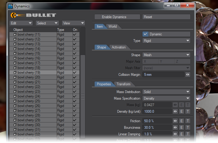
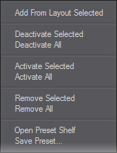
Inside this window, the first button at the top of the window is to Enable/Disable Dynamics globally in the scene. The same button is present on Layout’s FX Tools tab for ease of access. Next to it is a Reset button, use it when the simulation isn’t working as you’d expect. The Edit dropdown menu presents several options to add, deactivate and activate or remove selected or all items like so:
You can also open the Preset shelf (F8 when the Bullet Dynamics window is active) or save presets for the selected dynamic item. Currently, the Bullet properties that can be saved within presets are:
- Density
- Friction
- Bounciness
- Linear and Angular Damping
- Glue Strength
- Breaking Angle
- Breaking Distance
- Merge Points
- Mesh filter
- Linear and angular stiffness
- Shape retention
- Damping, drag and lift coefficients
- Volume scaling and conservation
- Dynamic friction
- Self collision
- Solver iterations
- For forces: field type, strength, density, axis, direction
In fact, it’s probably now easier to say which settings are not saved to presets and why. They are:
- Enable/disable dynamics item
- Shape
- Activation and deactivation settings
- Collision margin
In addition, neither the mass method nor the given mass are saved to presets currently. The intention is that presets save material properties, independent of the specific mesh used.
Next to the Edit menu is a button that allows the user to either show all of a scene’s items or only those that have some dynamic properties.
Select and View Dropdowns

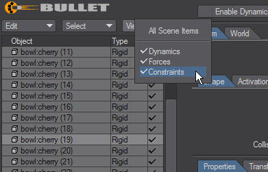
Choosing and viewing items in the Bullet Item Properties window.
Bullet Dynamics Properties
The other buttons in the window are divided into two tabs and a list. The list contains every dynamic item in the scene along with the type of dynamic body assigned and a checkmark for individually enabling or disabling the object.
Item Tab
- Dynamic - This button replicates the functionality found in the list, for enabling or disabling an individual object. (You can also double-click an item in the list to activate/deactivate it from dynamics calculations, remember, when an item is disabled, the dynamics solution will need re-calculating).
- Type - Shows a dropdown with the same dynamic type choices as presented in the Layout FX Tools tab - Rigid , Parts, Static, Kinematic, Deforming ; the constraints Point to Point , Hinge , Slider , Cone Twist and 6 DoF ; and the Forces Forcefield , Vortex and Explosion .
Shape sub-Tab
- Shape - The collision shape the object has for Bullet. This is a dropdown with five options - Box , Sphere , Capsule , Cylinder , Convex Pieces and Mesh . Convex Pieces approximates the mesh shape as a set of convex pieces. Convex pieces are faster to simulate than Mesh shapes, but take time to pre-process (the “Decomposing” passes you might see happen). Since Convex Pieces only approximates the shape you can lose some details that may or may not be important, unlike using Mesh which uses the shape exactly. The other four are simplified shapes to make calculation swifter.
- Major Axis - Only available when using a predefined Shape, not Convex Pieces or Mesh , and usable mainly with the Capsule or Cylinder shapes. It defaults to Y since that is the axis most used for modelling objects that stand up, but if you are creating a dynamic pencil, for instance, you might choose X or Z, depending on the direction in which the pencil is lying.
- Mesh Filter - This setting is only available with Kinematic objects and determines which parts of a mesh are subject to dynamic simulation. It is further detailed in the Kinematic section.
Collision Margin - Adds a margin to the collision shape. It makes the shapes a bit thicker and can prevent fast moving objects from tunneling through other objects.
When using the built-in shapes, a Collision Margin greater than 0 is recommended (5 mm). It won’t offset your objects, but helps with calculation errors, this is especially true for smaller objects. When using any of the Mesh modes, the Collision Margin will offset your geometry, but can greatly reduce any calculation errors, so try setting to a low value, and only set to 0 mm if you really need to.
Activation sub-Tab
- Initial Activation - Sets whether the object starts off active (affected by forces such as gravity), or sleeping (not affected by forces until the first time the object is hit). When an object stops moving (or close enough), it will be put to sleep, unless it is set to the third option, Always Active . The fourth option, Activate on Last Key allows you to give an item some momentum before it is affected by Bullet dynamics and works based on the velocity of the motion keys you have assigned the item.
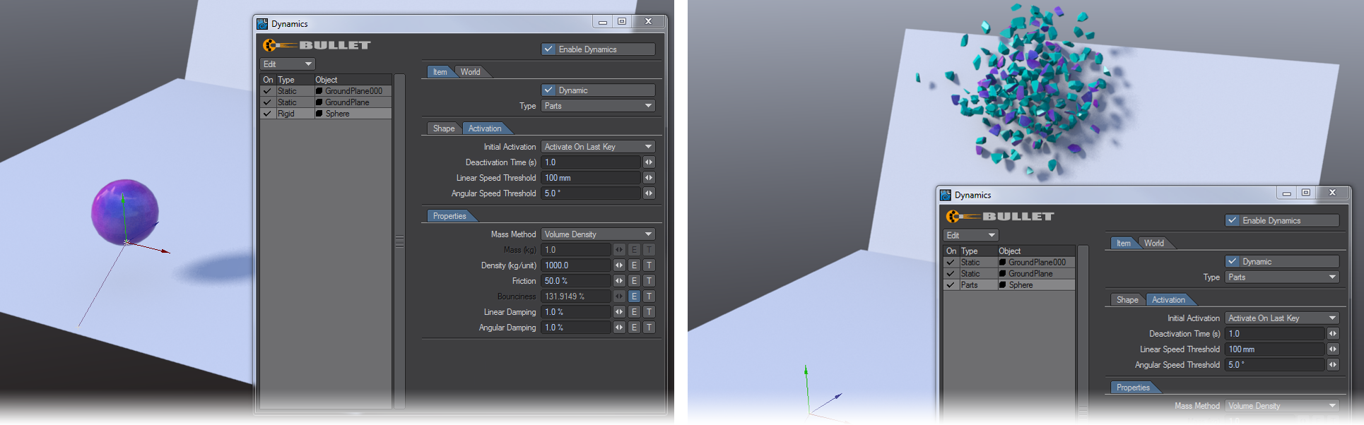
- Two keyframes have been set for the ball at 0 and 3. When the last keyframe has passed, Bullet takes over using the velocity and vector set by the keyframes. The distance between the two keyed positions will give the velocity of the ball so setting a wider gap will make for a faster trajectory.
- Deactivation Time (s) - This allows you to control when dynamic items are set to rest by Bullet. Measured in seconds, this value sets how long a dynamic item’s linear or rotational speed has to be under the threshold settings, before it is then put to sleep by Bullet. This helps control any jittering of items near the end of a simulation. Sleeping items will naturally be awoken if they are disturbed by any further collisions.
- Linear Speed Threshold - This allows you to set the maximum distance an item can travel per second to be considered by the Deactivation Time before it is stopped by Bullet.
- Angular Speed Threshold - Same as Linear Speed, but for rotation. This sets the threshold rotation speed (degrees per second) which the item needs to be below to be considered by the Deactivation Time before it is stopped by Bullet.
Under the Shape and Activation sub-tabs are two further sub-tabs. Properties and Transform. Properties contains the individual properties of a specific Bullet Type (Rigid; Static; Vortex; 6 DoF, etc.), which are all detailed below for the specific Bullet types.
Transform sub-Tab
![]()
The controls here are for adjusting the predefined shape you have chosen for your collision - they are not available when Convex Pieces or Mesh is chosen as the Shape for your dynamic item.
World Tab
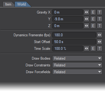
The settings on this tab affect all of a scene’s Bullet simulations.
- Gravity X/Y/Z - Although the default is set to an Earth standard gravitational acceleration of -9.8 m nothing prevents you from having your gravity point in any direction, or even varying it using Envelopes and Textures.
- Dynamics Framerate (fps) - Set the frames per second for dynamics calculations. By default this is at 180 fps. Decreasing the value will result in faster calculation times at the expense of simulation accuracy (objects penetrating each other). Increasing will result in the opposite, more accurate simulation, but with slower calculation times.
- Start Offset - Chooses when to start the beginning of the dynamic simulation. If using Frame Number , SMPTE Time Code or Film Key Code the number you input will be converted to the frame equivalent in that format. If using Seconds , there will be no conversion. For example, a value of 50 in this field translates to: 50; 00:00:02:02; 3 +02 and 50.0 s respectively when using an FPS setting of 24 in Options.
- Time Scale - By default this is set at 100%, however, using an Envelope you can slow down, speed up or even reverse dynamics time independent of the scene time to create ‘Bullet Time’ animations like those first popularized in the ‘Matrix’ films.
- Draw Collision Shapes - There are three dropdown menus here - Draw Bodies , Draw Constraints and Draw Forcefields . Each of them has the following options:
- None - No collision shapes are drawn for the scene.
- All - the default; all collision shapes are drawn for the scene.
- Selected - only the item(s) selected in Layout will have their collision shapes drawn.
Related - the items in the selected hierarchy have their collision shapes drawn.
By default, all three Draw Collison Shapes settings are set to Related.
- Reset - If you ever see results in Bullet that seem strange to you, it could be the cache needs re-calculating from scratch. This button does just that, it clears and resets the cache Bullet is using when solving the dynamics, then rebuilds it when you scrub or play the timeline.
Rigid, Static and Kinematic Properties
- Mass Distribution - Determines how Bullet considers the mass of an object to be distributed. Two objects with different mass distributions can behave differently even if they have the same shape and weight the same. For example, a solid sphere can act differently than a hollow sphere. Bullet offers several distribution methods:
- Solid - Mass is distributed through the object, it is solid.
- Surface - The mass is distributed over the surface of the object, the object is hollow.
- Vertices - The mass is concentrated at the vertices of the mesh of the object only.
- Mass Specification - Determines how Bullet calculates the ‘heaviness’ of an item. Bullet can calculate an object’s ‘weight’ based on mass, or density. Mass is the overall ‘weight’ regardless of what the object is made of or how big it is. For example: you can set a 1 m cube to be the same weight as a 10 m cube, and they will clearly be the same weight, whereas if you set the density of a 1 m and 10 m cube to 1 kg, the 1 m cube’s mass will be 1 kg/m cubed (1 m x 1 m x 1 m x 1 kg = 1 kg) and the 10 m cube would be 1,000 kg/m cubed (10 m x 10 m x 10 m x 1 kg = 1,000 kg). Quite a difference in Bullet’s world! Bullet offers several calculation methods:
- Mass (kg) - Only available when Mass Specification is set to Given Mass . For Parts mode, the amount is divided up accordingly to each part’s overall volume, so smaller pieces will be lighter than larger pieces, as expected.
- Density (kg/unit) - Only available when Mass Specification is set to Density . The mass of the object is then calculated by multiplying the unit specified (kg) per the unit type set in either of the density modes. Therefore; kg x (Volume/Area/Number of Points).
Friction - The friction coefficient of the object. Makes objects slow down when in contact with other items.
In order for Friction to have an effect, colliding objects must each have a non-zero Friction value.
Bounciness - Determines the level of rebound when objects collide with each other.
In order for Bounciness to have an effect, colliding objects must each have a non-zero Bounciness value.
- Linear Damping - Dampens the linear (translational) motion of the object to slow down its movement.
- Angular Damping - Dampens the Angular (rotational) motion of the object to slow down its spinning.
Parts Properties
When Parts is chosen as the body type for an object, additional parameters become available:
Glue Strength - This determines how tightly bound parts are to each other. A low value will have them explode apart at first touch, a high value will keep them together.
Glue Strength with no Breaking Angle/Distance set is very dependent on the item’s scale and Mass Method used. Be aware that if your object’s weight/mass is too low, Glue Strength can appear to have little effect when set above 0%. Try increasing your object’s weight/mass until you see the effect.
- Breaking Angle - The threshold angle up to which parts can twist/bend before the ‘bond’ (Glue Strength) between them breaks and the parts then separate.
- Breaking Distance - The threshold distance up to which parts are allowed to move apart before the ‘bond’ (Glue Strength) between them breaks and the parts then separate.
- Merge Points toggle - When active, Merge Points will attempt to ensure that matching vertices on either side of a fracture have the same position, ensuring the mesh stays ‘air-tight’ while the parts are not broken.. This does have a cost in processing time and memory.
Example - Choreograph your destruction
Deforming Body Properties
When Deforming is chosen as the body type for an object, additional parameters become available:
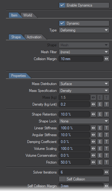
- Mesh Filter - This uses the chosen weight map in the geometry to determine what parts are dynamic. Any polygons with vertices in the chosen geometry with a non-zero value in the weight map will be considered as a deforming body, those with no weight map value are ignored by Bullet.
- Shape Retention - This works in two ways. With Shape Lock set to None, it determines how little or much the mesh is deformed by Bullet. This mode is controlled completely by dynamics. If you set Shape Lock to one of the other options, your object will react in different ways, as noted below.
- Shape Lock - works in conjunction with Shape Retention . It presents a dropdown with four choices:
- None - The shape’s translation and rotation are fully controlled by Bullet;
- Translation - Translation responds to keyframing. Depending on the level of Shape Retention set Translation will still respond to the dynamic solution as well. Rotation is still completely controlled by Bullet;
- Rotation - The opposite. Rotation can be keyframed but Bullet controls the translation;
- Translation & Rotation - The mesh will follow the keyframed rotation and translation, but will be reacting to dynamics in relation to the motion.
- Linear Stiffness - How resistant edges are to stretching or shrinking, or how stiff or stretchy the object is. The higher the value the more it will attempt to maintain the lengths of the edges.
- Angular Stiffness - How resistant the object is to bending. The higher the value the more it will attempt to maintain the angles between edges.
- Damping Coefficient - Dampens the motion of the vertices.
- Volume Scaling - Scales the volume of the object, inflating or deflating it.
- Volume Conservation - How well the object maintains the (scaled) volume. When set to 100 % it attempts to keep the volume of the object equal to the target volume; set to 0 % it doesn’t conserve the volume at all.
- Friction - Defines the friction of the softbody. 0 % for frictionless (lots of sliding), 100 % for maximum friction (no sliding).
- Solver Iterations - How many passes are done by the solver to solve the linear and angular stiffness constraints. Higher values take longer to calculate, but increase the simulation’s accuracy.
- Self-Collision - Enable/disable detection of and response to the softbody colliding with itself.
- Self-Collision Margin - The collision margin used for self-collision only, unlike the other collision margin which is used for collisions between different objects.
Make sure you set the Subdivision Order after Displacement or last for any Deforming Body subpatch objects or they will not work. Subdivision Order does not matter for polygonal objects.
Example - Getting started with Deforming Bodies
Example - Animating a chain with Bullet
Using a Deforming object for Collision
When using a character or anything else deformed by bones, morphs or displacement as a softbody collider, you need to transform the mesh itself (or part of it) into a Bullet Deforming body.
If you want to maintain the original shape of the deformed object, you need to set some parameters in the Bullet Softbodies panel:
- Shape Retention must be set to 100%
- Shape Lock must be set to Translation & Rotation
- Both Linear and Angular Stiffness must be set to 0
- Volume Conservation must be set to 0.
Use simple kinematic shape objects parented to the bones of characters to create effective softbody colliders. Capsules are perfect for this.