Bullet Constraints
We’ve given an overview of the different constraints for Bullet higher on this page. Now we will go into how to use them in a scene. The simplest way to add a constraint is to have two Bullet objects in your scene already, select them both and hit the Constraint you want in the FXTools tab, but there are many other ways to create the Constraints you want.
Example - First Constraint
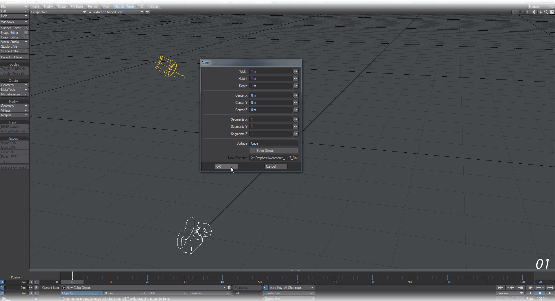
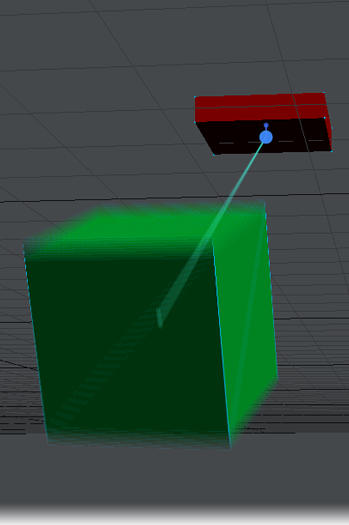
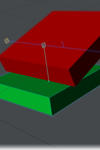
- We’ll start very simply. Create a standard Cube with the Modeler Tools tab. On the FX Tools tab, make this object a Static Body .
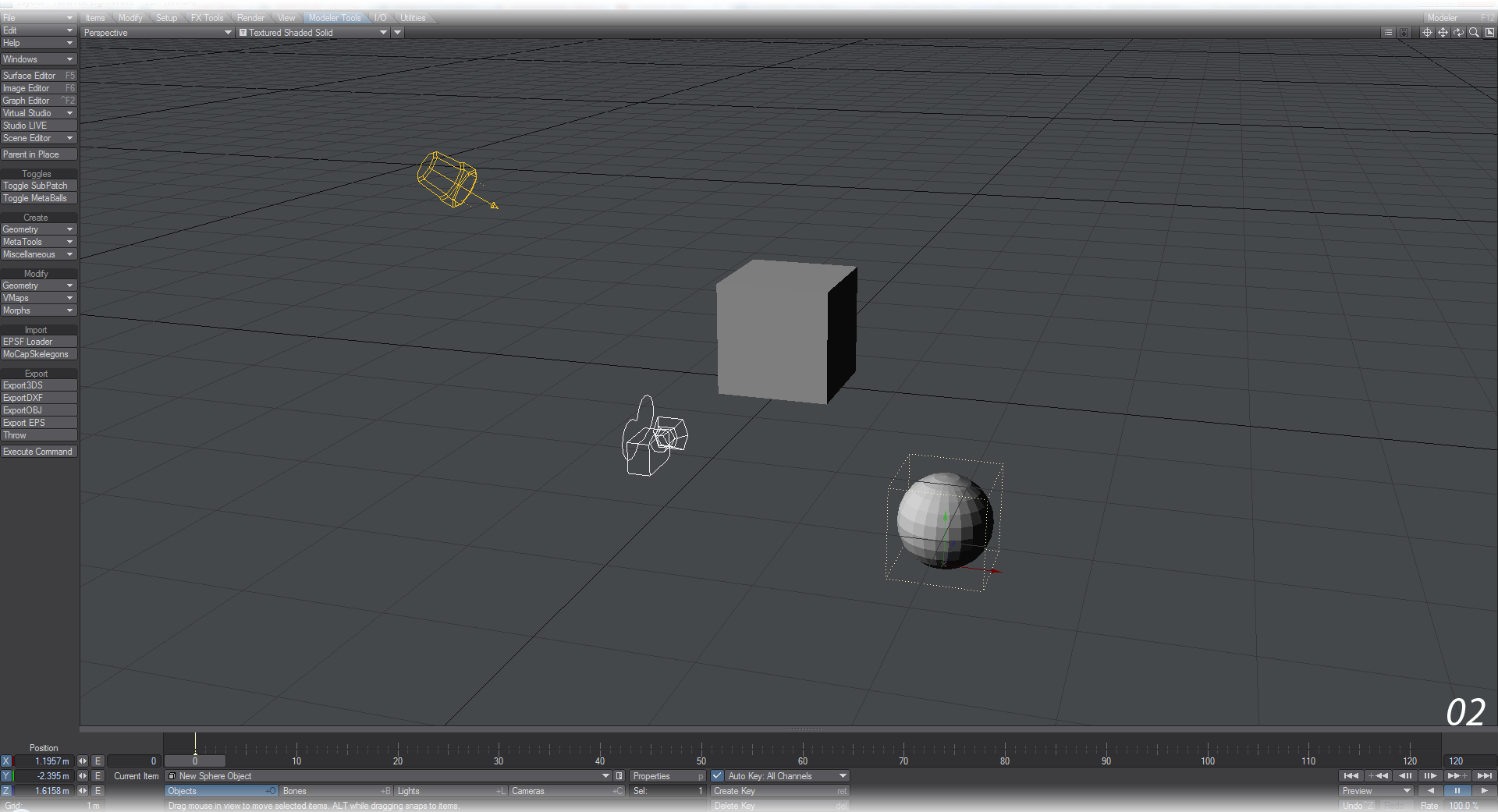
- Back to Modeler Tools and create a standard Sphere . Drop it on the Y so it’s below the Cube and move it a little to the side and back. On the FX Tools tab, make this object a Rigid Body .
- Select your Cube , hold down Shift and select your Sphere again. On the FX Tools tab, click Point to Point in the Constraints.
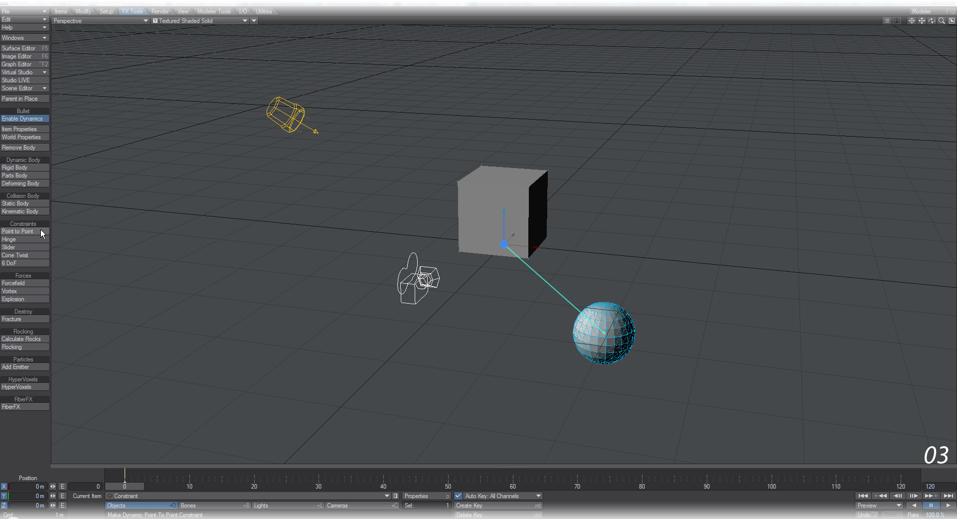
- Hit Play.

You can change the Point to Point Constraint for the other Constraints as you like. To do so, you need to visit the Constraint in the Bullet Item Properties window because if you just repeat the steps to make the first constraint you will merely add another, not replace it.
General Constraint Rules
Before we detail each of the different Constraints and how to use them, there are some rules that apply to all of them.
- The constraints in Bullet are designed to attach objects together, not to stand in for some invisible long wire. For a visible link, you will need to create geometry.
- To create a Constraint between a Bullet item and another, select the “Head” first, then the acting object, then hit the constraint you wish to use. This will create a Null object, set to the constraint chosen, with the first and second objects selected as the two Bodies for the constraint. You can also have a single object selected and choose your constraint. Doing this will set the current object as the constraint and you will need to visit the Bullet Item Properties window to choose Attach Body 1 and Attach Body 2.
- The “Head” of a Constraint will be based on a Null placed at the center of mass of the head object, whose position, rotation and scale can be changed, but not animated. Best to do this with Enable Bullet Dynamics deactivated.
- All constraints are Breakable. For the specific Constraint, visit the Activation tab and set the Breaking Force. You can set an Envelope or Texture for the Breaking Force. As an explanation of how Breaking Force works think of a 1 kg weight hanging on a constraint in Earth gravity. This weight exerts a force of 1*9.8=9.8 on the constraint. So if the Breaking Force is set to 9, the constraint will break. If it is 10, it will not (at least not until some more force is introduced, for example through a collision).
- All Constraints have an Enable Collision setting. When on, collision detection is enabled between the two bodies connected by the constraint. When two bodies connected by a constraint are set up so that they initially touch or intersect, instability can occur due to collision detection wanting to move the bodies apart, while the constraint tries to keep them together. In a bone rig, for example, it is typical to disable collision detection between connected bones for this reason, and to use rotation limits to stop a child bone from rotating too far into the parent bone.
- All Constraints apart from Point to Point can have Limits set. Limits will be explained with each Constraint, but mean that you can control how far Hinges bend, for example.
- Constraints apart from Point to Point and Spring can have Motors. Motors can act as brakes, slowing down a motion, or accelerators to give motion to things that are otherwise static. A Motor has two settings: Target Motor Speed and Motor Force.
- The 6 DoF Constraint also has Linear and Rotational Springs. If you are using a Layout-created default 1 m Cube as a test object, try a spring stiffness of something on the order of 50,000 as a start (based on the mass of the object at 1,000 kg/unit) and adjust up and down to suit.
- While Bullet is normally used only with objects, you can apply constraints to other scene items. Try making a chain of festive decoration lights, or restraining the camera to a dynamically-animated object.
To create a chain of items, select the head of the chain first, then select the rest of the chain in order and hit the constraint you wish to use. They will all be set up correctly in the Bullet window.
Point to Point
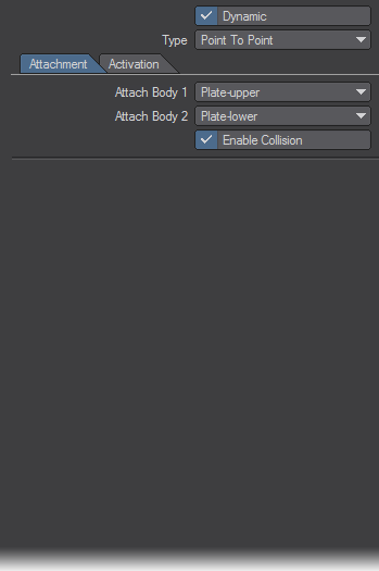
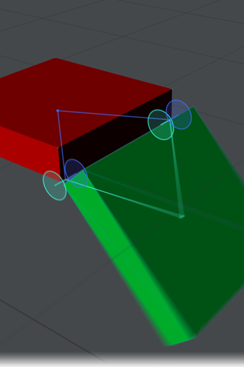
The simplest of the constraints, also known as the ball socket joint. It is represented by a single line in OpenGL. The only option on the Attachment tab is Enable Collision. There is no damping.
Example - Point-to-Point
Hinge
The Hinge only bends around one axis. As its name implies, it’s very useful for making hinges for doors etc.., but for the same reason that a door has two or more hinges, it makes sense to do the same in Bullet because otherwise torsion can cause problems. If you would like hinges that are stiffer, harder to move, use Motors. Keep the Target Motor Speed at 0° but increase the force until you achieve the stiffness you want. Bear in mind that you might want to increase the Force in a negative sense if your hinge bends in the opposite direction.
Example - Hinge
Slider
The Slider constraint offers translation along a single axis. You can set limits for the distance of the slide and also for how much Body 2 swings around the axis of the slider. Again, you can use a Motor to slow downslope motion or move upslope.
Example - Slider
Cone Twist
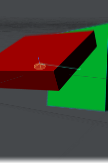
A Cone Twist constraint is a little like a Point to Point, only with more restrictions. There are Limits and Motors that can be used to better sculpt the motion you require.
Example - Cone Twist
 Spring
The Spring constraint can also be used within the 6DoF constraint, however that constraint is a bit complex if all you want it a simple linear or angular bounce. Spring follows the same rules we’ve already encountered with other constraints with regards to attaching bodies and enabling collision, but the main points of interaction are the Spring controls. By default, Linear Spring Stiffness is set to 10000 to give a satisfying result with default Modeler Tools dynamic objects. You can bring your spring to a halt using the Linear Spring Damping setting, but be aware that small values work best with this, larger values tend to look unrealistic.
To create an angular Spring it should be noted that the Spring is always around the axis of the constraint. If you wish to make a vertical spring you’ll need to create a horizontal constraint as shown in the metronome example in the content.
Example - Mars Rover
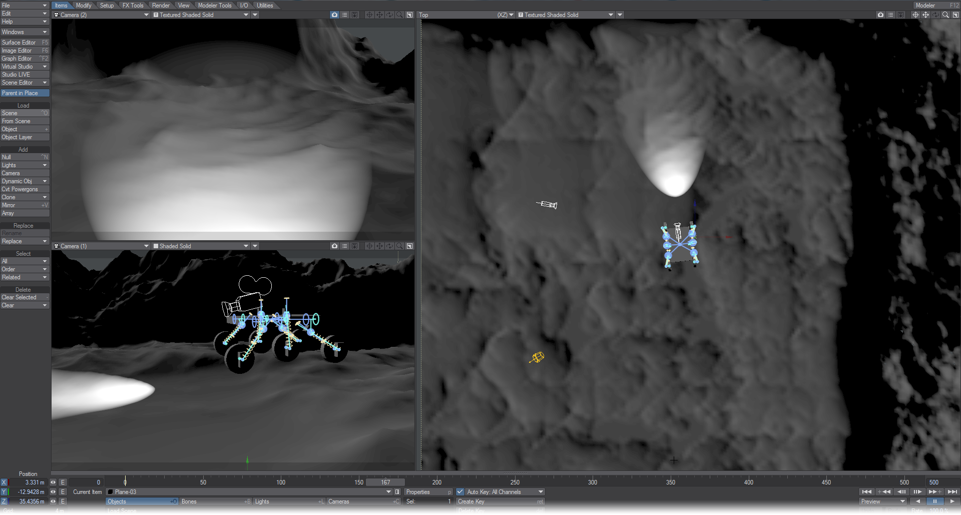
Load the Mars Rover scene from the content. This complex example shows how you can use Springs to recreate a suspension system on a six-wheeled vehicle that is driven completely dynamically.
6 DoF
The most complex of Bullet constraints, this offers both directional and rotational possibilities that are set up in the same way as the separate Slider and Cone Twist constraints. In addition to the Limits and Motors found in almost all other constraints, there are also settings for Springs. To work well, a spring needs to counteract the mass of the object hanging off it as well as gravity.