Bullet Dynamics
About Bullet Dynamics

LightWave 11 added Erwin Coumans’ open source, production-proven Bullet Physics Library to its dynamics tools. This feature is extremely simple to add to a scene, but its use is a little different from the HardFX plugin existing LightWave users are familiar with.

In order to ensure dynamics calculations are free of problems, it is worth noting these guidelines:
- Make your models not too small, or too large, as Bullet gives more predictable results when working with objects sized roughly between 0.4 - 10 m.
- Any collision objects such as ground planes should not be infinitely thin but have some thickness.
- Objects made of triangles and quads will generally behave better.
- When using the built-in shapes within Bullet, have some Collision Margin set. 5mm is a good default.
- Bullet doesn’t work with negative frame numbers.
- Prepare your objects for dynamics, ensuring:
- Models are ‘air-tight’, meaning all points are merged and there are no un-modeled holes in your mesh (missing polygons).
- All single points and 2-point poly chains are removed.
- Objects don’t have extremely long, thin polygons.
Example - Getting Started with Bullet
Overview of Controls
In the Layout FX Tools tab that hosts Bullet as well as other motion effects items Bullet’s properties are split into the following groups:
Bullet Group:
- Enable Dynamics - This turns Bullet on and off globally for the scene.
- Item Properties - This opens Bullet Properties on the Item tab. If any dynamic objects in Layout are selected when this is clicked, they will be selected in the Bullet panel.
- World Properties - This opens the Bullet Properties on the World tab.
- Remove Body - Removes selected objects from Bullet, so they are no longer part of any calculations. The Bullet settings for the objects will be lost.
Dynamic Body:
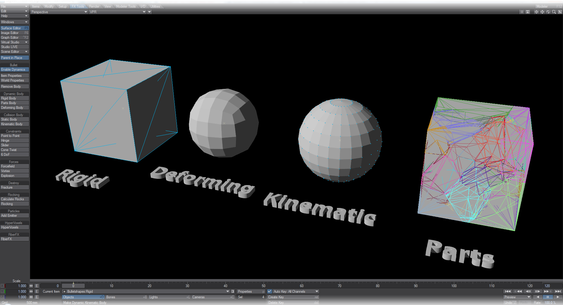
- Rigid Body - The object will be subject to all the Hard Body settings that Bullet can offer, such as Gravity or Density, but will not break apart.
- Parts Body - This is a great accompaniment for the Fracture tool. It keeps your object whole until there is a collision event.
- Deforming Body - This adds a Soft Body matrix to your object. Your mesh will now be deformed following the rules you set for it.
Collision Body:
- Static Body - This is the type to add for objects that will not move or be subject to other forces, but will react with other bodies. A floor is a good example of a static body.
- Kinematic Body - Gives the selected object characteristics similar to Static, but it can be moved through keyframed animation, thus it is an object that is under user control. As with Static, it affects other dynamic items but cannot be affected by them.
By default, LightWave draws an overlay on dynamic objects in OpenGL to show that not only are they dynamic, but what type.
Constraints:

- Point to Point - The Point to Point constraint, also known as ball-socket joint, limits the translation so that the local pivot points of two rigid bodies match in world space. A chain of rigid bodies can be connected using this constraint. No other controls than just attach A to B.
- Hinge - The Hinge constraint, or joint, restricts two additional angular degrees of freedom, so the body can only rotate around one axis, the hinge axis. This can be useful to represent doors or wheels rotating around one axis. It contains Limits and Motors.
- Slider - The Slider constraint allows the body to rotate around one axis and translate along this axis. It contains Limits and Motors.
- Spring - The Spring constraint can create linear springs as shown; or angular springs, like the winding of a watch spring.
- Cone Twist - The Cone Twist is a special point-to-point constraint that adds cone and twist axis limits. The x-axis serves as twist axis. It is useful when creating ragdolls, especially for limbs like the upper arm. It contains Limits and Motors.
- Spring - The Spring constraint emulates real-world springs, both linear and rotational (like the winding of a clock). Contains Limits.
- 6 DoF - This generic constraint can emulate a variety of standard constraints, by configuring each of the six degrees of freedom (DoF). The first three DoF axes are linear axes, which represent the translation of rigid bodies, and the latter three axes represent angular motion. Each axis can be either locked, free or limited. Note that several combinations that include free and/or limited angular degrees of freedom are undefined. It contains Limits, Motors, and Springs.
You can simulate resistance on a hinge constraint by enabling the motor. Keep the target speed at 0 and increase the motor force. An initial try for a motor force would be about the mass of the object times the gravity. Think about how you would make something real also. You don’t have a door with only one hinge. That can cause twisting and even breaking the hinge. You can have multiple constraints between two objects. So for a door, you could put two hinges between the door and the wall. Or you could have the hinge constraint in the middle, with point-to-point constraints at the corners. The key is that the error due to the twisting is relatively small in the middle, but at the corners, it is a large positional error. So like in real life, add some supports at the corners to stop it from twisting apart.
Forces:
- Forcefield, Vortex, Explosion - These three Bullet Dynamics types share similarities in their settings and effect. They are global to a scene and affect all other dynamic objects in the scene although falloffs can be created using gradients to isolate the effects to certain regions of 3D space. Note, textures for Force settings using World Coordinates won’t work correctly.
- Bullet Item Properties Window
- Bullet Constraints
- Forcefield, Vortex and Explosion Properties
- Bullet Cache, Hierarchies and Bones
- Bullet and FiberFX
Examples:
- Baking Simulations - Creating static animations from simulations
- Further Examples - Other Bullet tutorials