Example - Getting Started with Nodes
Let’s begin our exploration of the Node Editor, its interface and general use by performing some of the everyday tasks it was designed for. Pay close attention as we step through some of the simple operations used in common node based texturing. There will be a few hints and tips not covered elsewhere in this manual.
The object of this tutorial-style instruction that we are about to start is primarily to familiarize you with the process of working with nodes. We will be focusing more on mouse and keyboard operations and the way the Node Editor handles itself in use rather than the actual texturing techniques involved in the steps we’re about to perform.
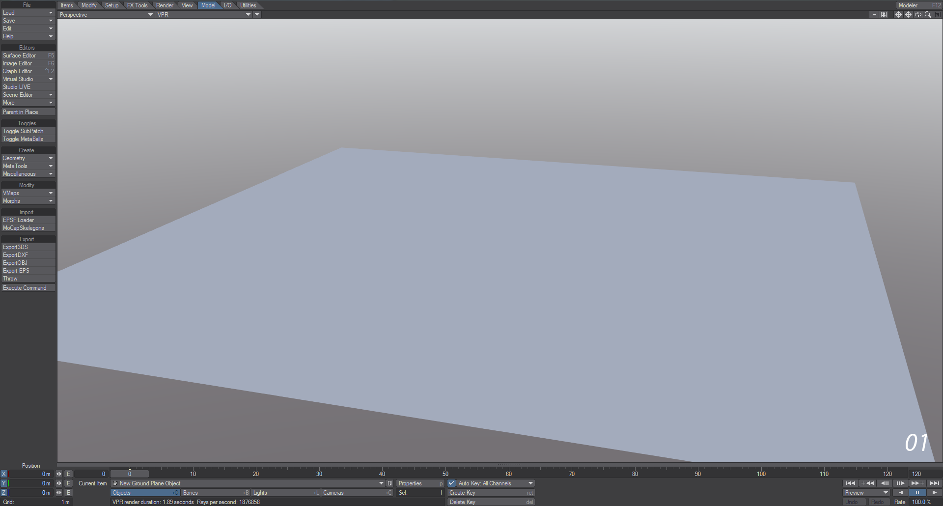
- Open Layout and add a Ground Plane using the Modeler Tools tab. You don’t need to make any changes to the settings so click OK. Next, start VPR by choosing it from the Viewport Display menu or hitting Ctrl-F9, then hold down Shift and click on the ground plane you made in the rendered view to open the Surface Editor.
- Double-click on the Ground Plane surface in the Surface Editor to open the Node Editor. Take a little time to arrange opened windows/panels in a configuration so that you can still see the VPR render in progress. Don’t forget you can always hit Tab to hide all windows and just show the Layout screen.
A good idea to perform any time you start a new surface is to create a new Preset Shelf Library. Open the Presets Shelf by hitting F8 and create a Library by right-clicking in the main area of the Surface Preset window and selecting Create Library from the Library submenu. Give the library the name you like.
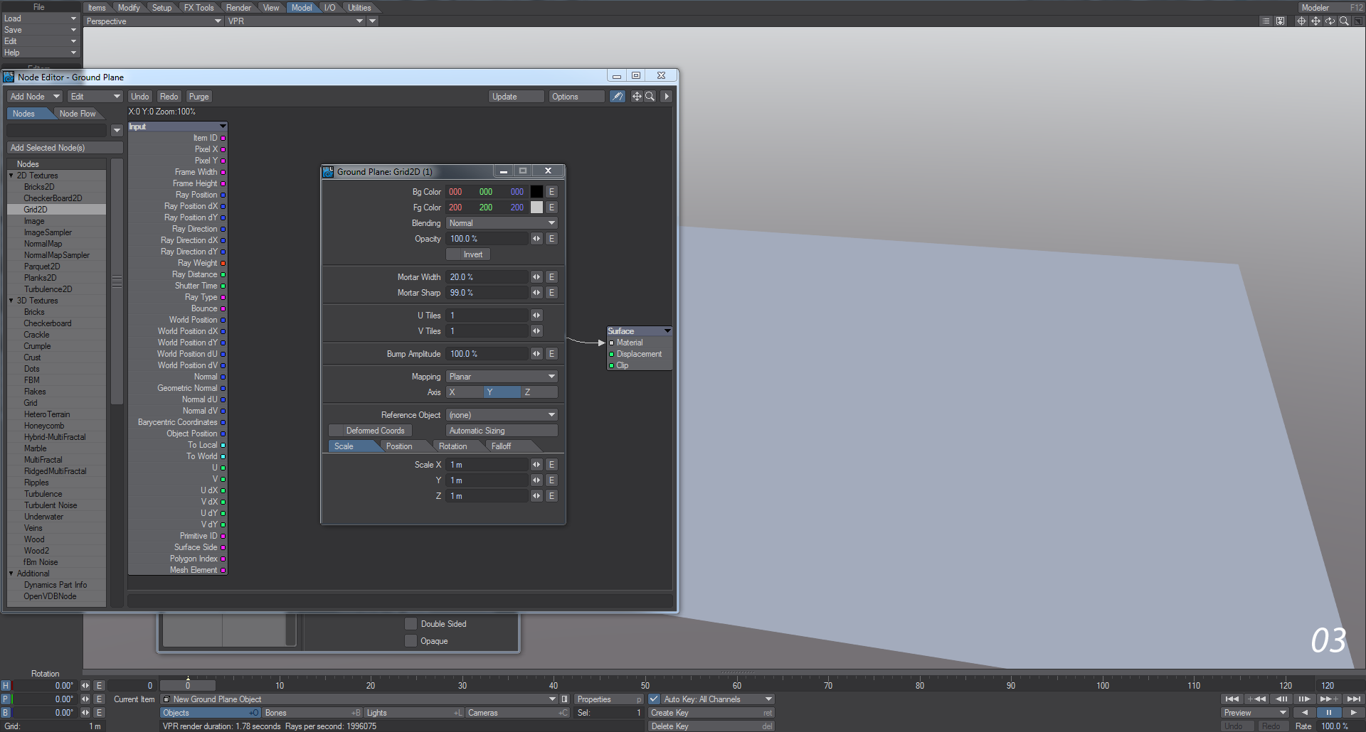
- Add Grid2D from the 2D Textures group on the left side of the Node Editor by double-clicking on its name. If you are working with the Embedded Edit Panel Extension Area open the properties for the Grid2D node will be displayed on the right-hand side of the Node Editor window. If it is not, just press enter or double click the node to open its floating edit panel. The only thing we want to change in this panel is the Mortar Sharp value which we will set to 99.0% and the Axis which we will set to Y by clicking on the Y button in the same panel.
Clicking Undo at the top of the Node Editor window, we will notice that the Grid2D node is removed from the Workspace area - meaning that the Undo and Redo functions respect only Workspace area actions, which is good to bear in mind as we work with the Node Editor interface.
Press Redo to get back the Grid2D node noticing that the 99% and the Y axis settings we entered before the undo operation are still intact.
- The Node Editor is set up with a logical flow construction from left to right. The colored dots and labels on the left-hand side of any node are that node's inputs. Any dots and labels located on the right-hand side of a node are that node's outputs. Inputs receive information from other nodes in the network while outputs send information.
Let’s see how this works by connecting the Grid2D's Color output to the material node's Color input.
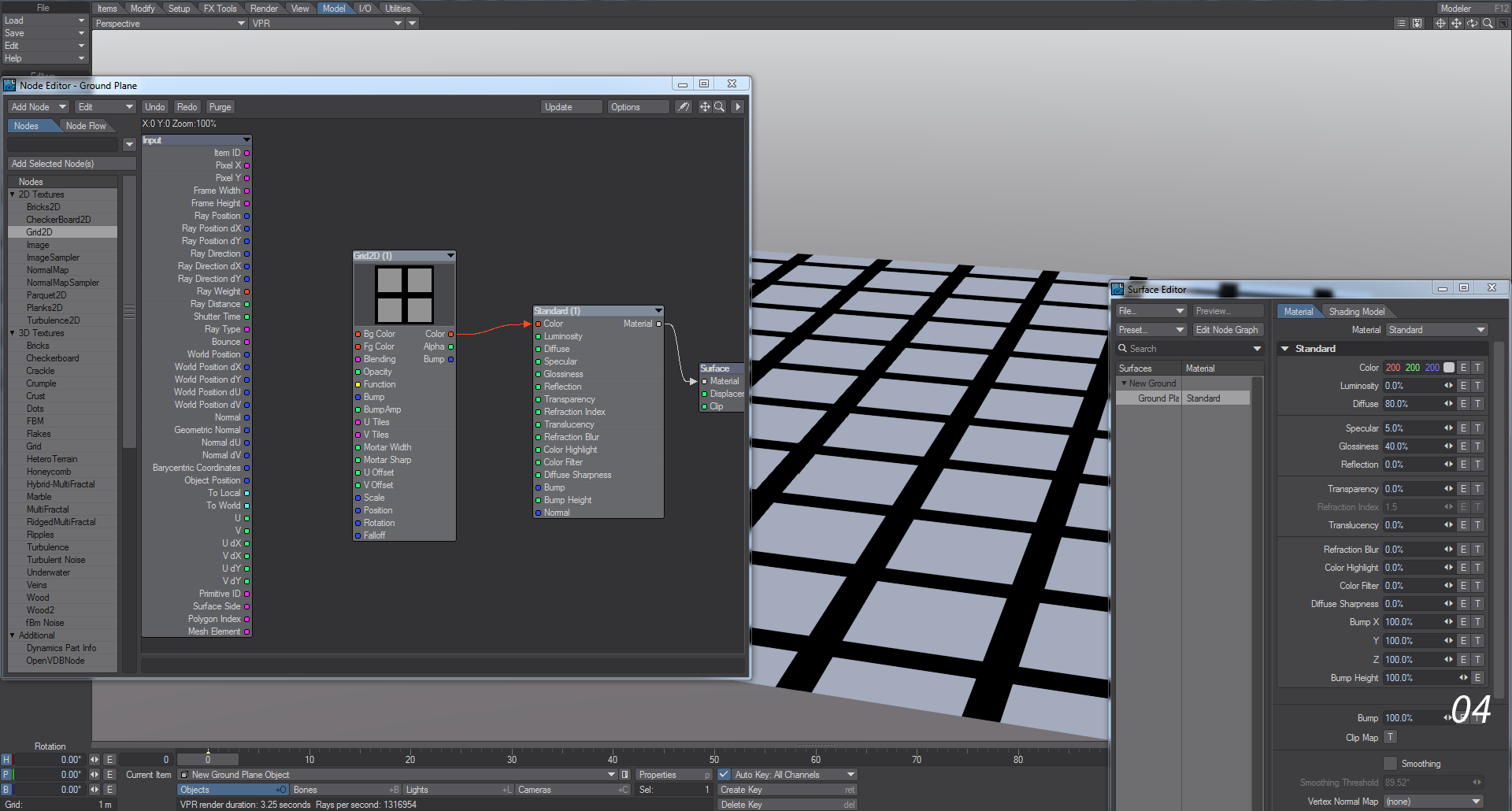
Place your mouse cursor over the red dot labeled Color on the right-hand side of the Grid2D node. Now perform a click and drag operation toward the Surface destination Node’s Color input dot. As you drag, an arrow-headed line will extend and follow your mouse cursor movements.
Notice that as your mouse moves into the body area of the Surface node that the arrowhead remains snapped to the input at the same latitude as your mouse cursor and not until your mouse cursor moves past the Surface node and emerges on the other side does the connection arrow unsnap and again begin following the mouse cursor. Position your mouse so that the arrow connects to the Surface nodes’ Color input and release the mouse button to complete the drag operation.
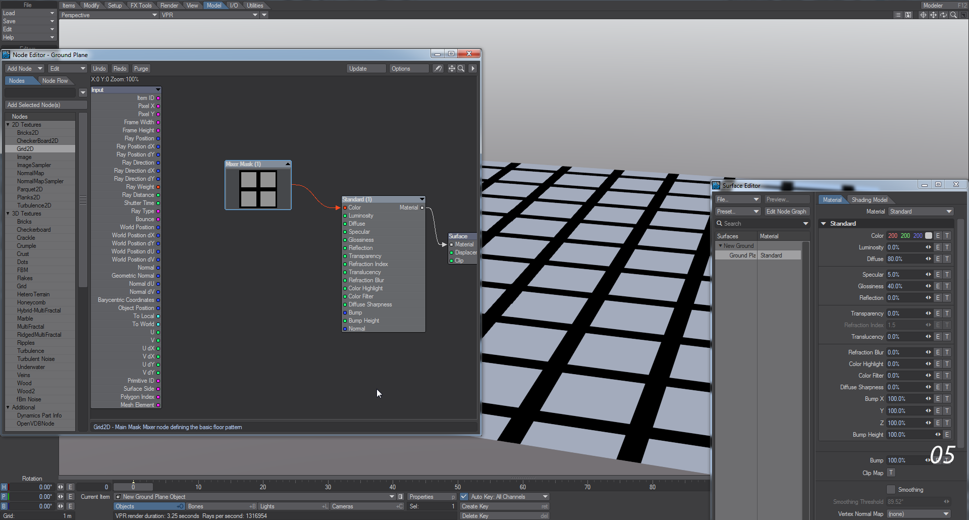
As you release your mouse button with the arrow connected to the Color input of the Surface destination node you will notice that the VPR display automatically renders the view of the floor object with the newly applied Grid2D procedural texture applied.
Add a preset for your surface in the Surface Editor.
- Click on the Grid2D node to select it, and press R. Enter the name "Mixer Mask" into the Rename Node requester that appears and press Enter. Renaming a node has no effect on its function but is useful for keeping track of what nodes are doing and the role they play in a network. The Node Comment Entry Area at the bottom of the Node Editor panel can also be used in this way. Whether either or both are used is a simple matter of user preference. With the node still selected click in the text entry area and enter some descriptive text such as: “Grid2D - Main Mask Mixer node defining the basic floor pattern” and press Enter when finished.
Collapse the newly named Mixer Mask node either by selecting it and pressing Shift-C or by clicking on the collapse toggle button in the node's title bar.
- Add the Parquet2D node from the 2D Textures group. Open its floating Edit Panel (Enter or Double Click) or use the embedded edit panel area to modify the following values:
Change U Tiles to 10, V Tiles to 10, and change the Axis to Y.
Now drag the Color output from the Parquet2D node to anywhere over the top of the Mixer Mask node and release the mouse button to finalize the drag operation.
Notice that dragging over the top of a collapsed node pops up an input selection menu.
Select BgColor from the menu and then expand the node either by pressing Shift-E or by clicking on the node's collapse toggle button.
You will also notice that VPR has again automatically updated with the new surface information.
Again double click on the Surface Editor preview display area to add a second preset to the preset library we created earlier. You can come back to this point in the texture creation anytime you may need to by double-clicking on the icon in the surface preset window.
Let’s try that now by double-clicking on the first icon you created, answer yes to the requester that appears, and look at the Node Editor Workspace area. Now click on the second preset you made, answer yes to the requester that appears, and we should be exactly back where we started before double-clicking on any of the preset icons.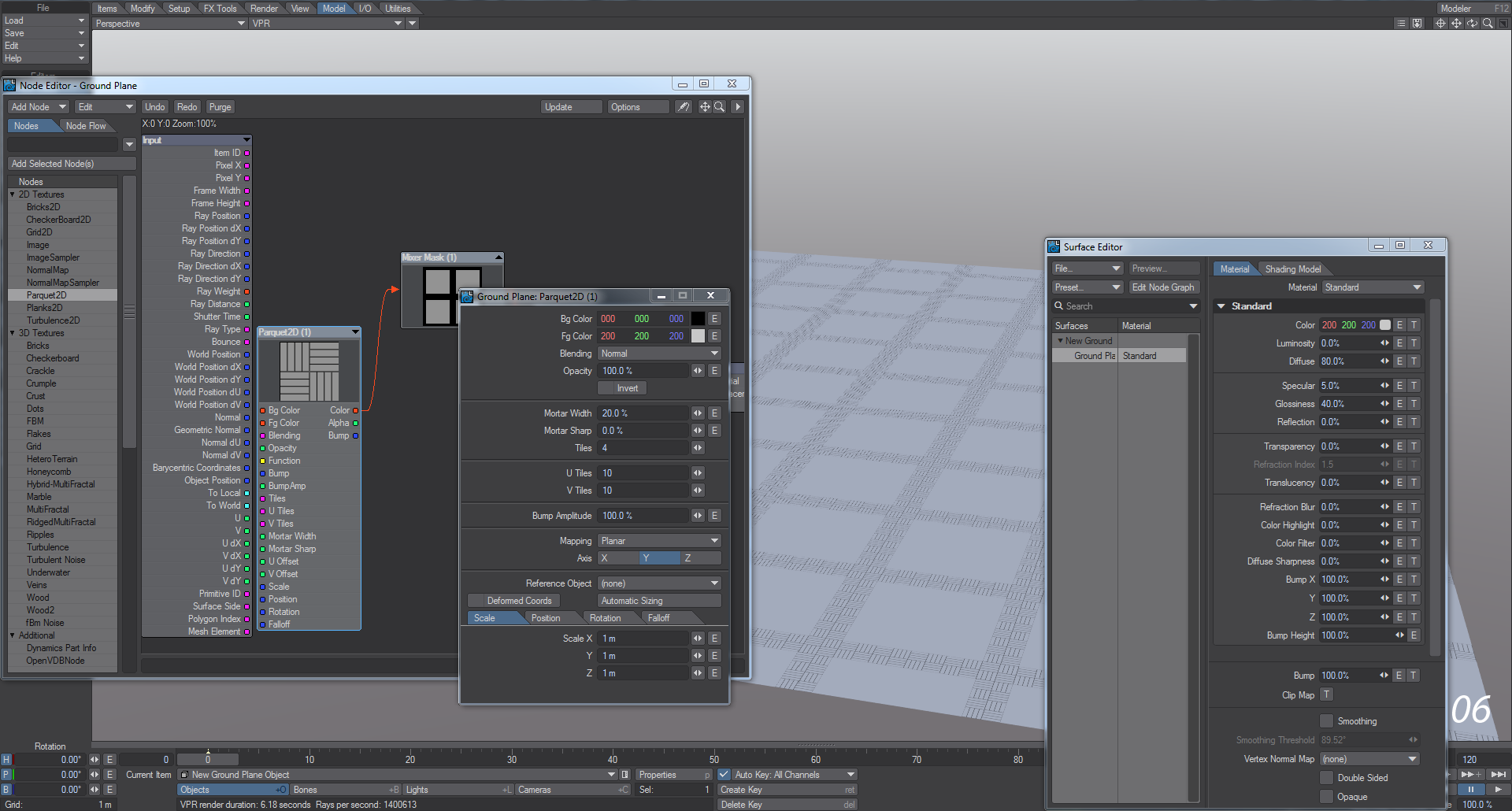
- Next, hold down the control key while right-clicking anywhere in the Node Editor Workspace area. You should see a popup menu that looks exactly like the Add Nodes menu at the top left of the Node Editor window.
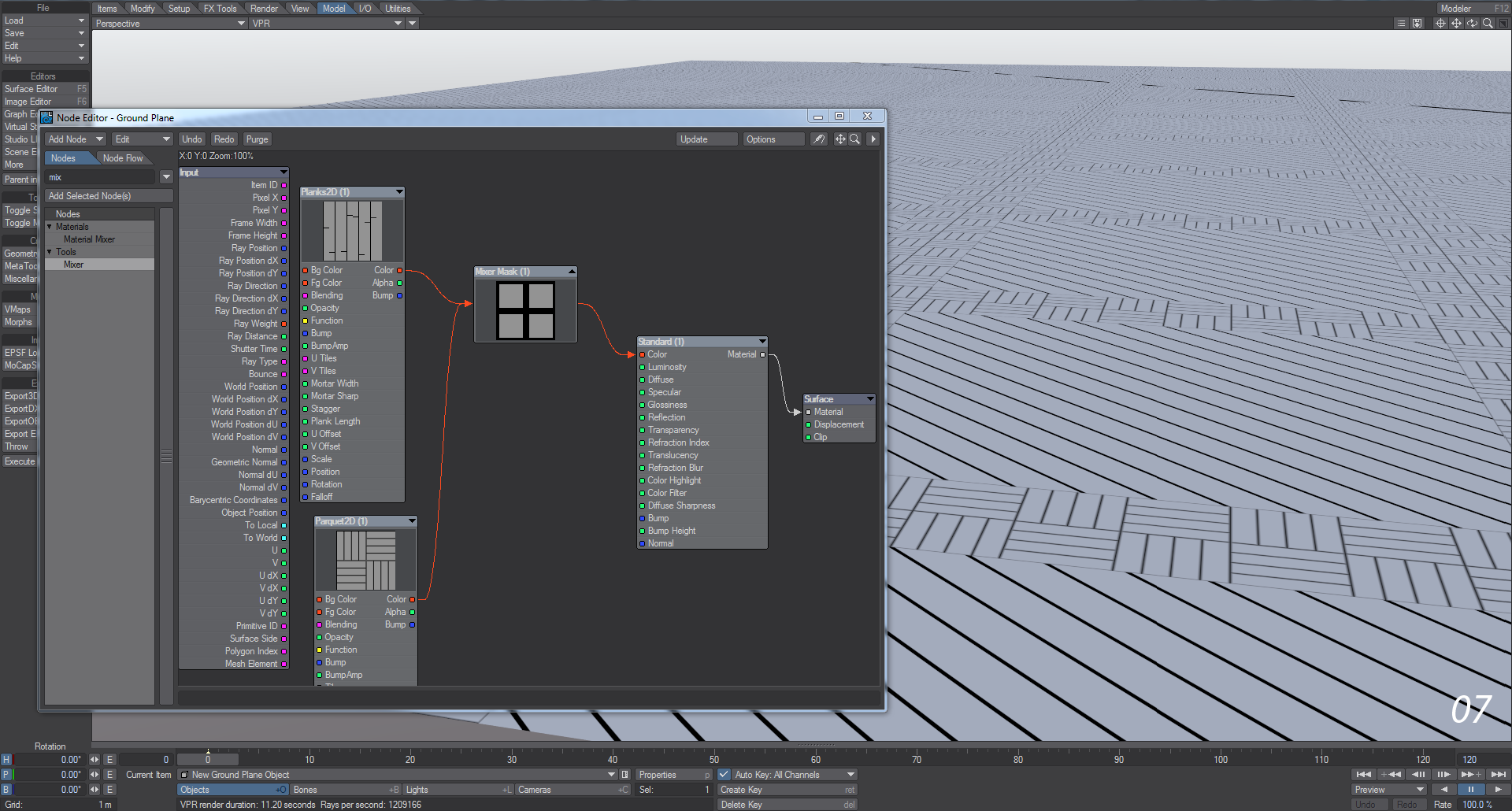
Select Planks2D from the 2D Textures submenu to add that node to the Workspace area.
Connect the Color output from the Planks2D node to the Fg Color input of the Mixer Mask node and then edit the Planks2D node as we did the others before modifying the following values:
Set Mortar Width to 10%.
Set Mortar Sharp to 80%.
Set both U Tiles and V Tiles to 20.
Set the Axis to Y
Set the Heading to 45° in the Rotation tab.
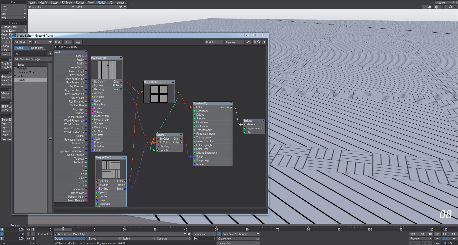
- Taking it one step further, let’s add bump to the Parquet and Planks parts of the node network. Here you will see that node outputs don’t always have to go to the same colored inputs. Add a Mixer node to your network by starting to type in the search field at the top of the node list.
Take the Bump output from the Parquet2D node and put it into the Bg Color input of the Mixer node. You’ll notice that the Bump output is blue, but the Bg Color input is red. The two connect all the same. Do the same with the Planks2D node to the Fg Color input on the Mixer. Lastly, add the Alpha output from the Grid2D node (now called Mixer Mask, remember) as the Opacity and take the Mixer’s Color output into the Surface node’s Bump input. You should now see that the planks and parquet have a subtle bump.
How does this work? A vector-type output supplies three channels of data (vertical, in-out and lateral). In the same way, a Color output also provides three channels of data (Red, Green, Blue) and all we are doing here is translating one to the other. The other potential connections are explained in detail here.
- You should see the lines of an uncolored wooden plank and parquet floor. The technique that is involved here is simple. The procedurally-generated Alpha channel of the Grid2D texture is being used to mask and contain each of the two patterns added to its foreground and background color layers respectively.
Go ahead and add another preset to the preset shelf.
On your own go ahead and try to add some wood grain and color the surfaces appropriately.
In conclusion, we saw the most common user operations for working with nodes in the Node Editor and explored several ways to achieve each one. Additionally, users new to node-based texture editing should have been able to glimpse some of the underlying power that node-based systems offer and how much easier they are to use.