Camera Settings
Resolution

The Resolution drop down menu will present you with a series of pre-defined resolutions to choose from for your render. It will automatically set the Width, Height and Pixel Aspect ratio fields.
You can add your own presets to this list, but it requires you to delve into the LW2019.cfg file. If this thought doesn’t scare you, then we’ll proceed.
If you look in your LW2019.0-64.cfg (Layout 2019.0 on Mac) file you see that near the top there are several lines that look like this:
ResolutionPreset 1920 1080 1 HDTV (1920 x 1080)
The first two numbers are the size of the frame; the next one is the pixel aspect ratio. The last bit of text is the title of the preset that will appear in the drop down menu.
Feel free to make your own lines. For instance here’s one you may wish to add to get the ball rolling:
ResolutionPreset 2480 3508 1 A4 page (300dpi)
As you can tell from the title, this Resolution Preset gives you a full A4 page at 300dpi. The width and height fields can be set to anything between 16 and 100,000. Be aware that larger resolutions can make serious demands on the memory of your machine.
The Resolution Multiplier gives you a much more consistent way of quickly checking a scene rather than changing the width and height fields when you want a small test render. It takes into account the scaling of things such as particle, line, and edge thickness, as well as the glow radius.
If you have selected a resolution preset and you alter the width or height fields, it will override any preset and the menu will then show the word Custom. If you have already set a resolution multiplier, it will then operate on the Width and Height settings you have chosen.
The resolution multiplier does not scale an image after it has been rendered. Therefore, it can be used in a situation where the boss asks for an image about “two-thirds as large again.” Deciding which resolution to use on a project is largely down to its intended use. An image for broadcast can almost always use the appropriate PAL or NTSC resolution presets. An image for print will always vary depending on the size of the final image, whereas film is usually one or two size settings.
Both provide high-resolution images that can take a long time to render and a lot of memory. If, however, you are rendering an animation for display on a computer, you will often want to use a lower resolution for reasons such as the running speed of the final animation and its file size.
Print Assistant
If you are working with print a lot, you should use Print Camera. This gives you a range of standard page sizes, adds Bleed, sets DPI/PPI and gives you a preview of your page.
Maximum Render Resolution
The maximum render resolution for 32-bit versions of LightWave was limited to 16,000 x 16,000 pixels. Machines running LightWave since v2018, only available as a 64-bit version, can render images up to 100,000 x 100,000 pixels given enough memory. Bear in mind that 100k x 100k is an extreme size. Just a blank image at this size requires around 149 GB of memory - 100k x 100k x (RGBA @ 4 bytes per channel = 16 bytes)/(1024 x 1024 x 1024) = 149 GB). Also, anything above 30,000 x 30,000 pixels won’t load into versions of Photoshop older than CS4.

Constrain
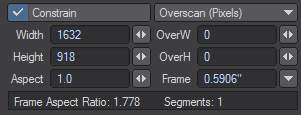
Often you will want to increase the size of your render but keep the same picture aspect ratio. The Constrain check keeps the Width and Height values in same proportion, which ever you change. You can uncheck the Constrain gadget and recheck it to change the aspect ratio of your rendered image.
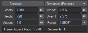
Overscan
You can set the overscan amount in pixels or in percent and the relations will be kept as you change.
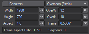
The overscan amount will be added to each side and displayed in the viewport as a lighter overlay than the normal frame overlay. You cannot extend a Limited Region into an overscan area.

Once you’ve been using a computer for a while you forget that pixels actually come in different shapes. Ones for NTSC TV are tall and thin; ones for PAL TV tend to be a bit fatter, while ones for print and HDTV are the same as those for computer screens – square as square can be.
The Pixel Aspect Ratio setting in LightWave is calculated by dividing the width of a pixel by its height. A pixel intended for print or a computer screen is square, as we said, so its aspect ratio is 1.0. Because NTSC pixels are taller than they are wide, the aspect ratio tends to be between 0.86 and 0.9. PAL ones, on the other hand, tend to vary between 1.01 and 1.06. Values for widescreen displays are considerably wider in both NTSC and PAL.
Why worry about the pixel aspect ratio? After all a pixel is a pixel, right? Well yes, but if you look at a perfectly round ball that has a radius of 50 cm and you are using an NTSC resolution preset, the ball will look squashed on a computer monitor, whereas it will look perfectly round on your NTSC monitor. When selecting one of the resolution presets you will notice that the pixel aspect ratio changes along with the resolutions for width and height. As for things looking squashed or stretched on your computer monitor, I’m afraid it’s either something you’ll have to get used to, or you will need an output to a proper broadcast monitor to reassure yourself.
Aperture Height (Frame)
You can change the aperture height, or Frame, of your virtual camera in LightWave to match the optical characteristics of a real world camera, especially for film work. Changing this setting will only affect the Depth of Field effect and the lens focal length.
Aperture Height is always listed in inches, even if you are using a metric unit system.
Frame Aspect Ratio
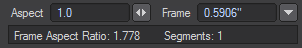
Before we move on, don’t confuse the pixel aspect ratio with the frame aspect ratio figure, often referred to simply as the aspect ratio. The way to work this out is to take the pixel width of a picture, divide it by the pixel height and multiply the result by the pixel aspect ratio. As an example, a standard VGA screen is 640 x 480. This equates to a frame aspect ratio of 1.333, which is the result of the following sum (640/480)*1 and converting it to a ratio. You will often see this figure quoted on the back of DVD cases to indicate the width of the display compared to its height (which indicates how much of your TV screen will be covered by black bars).
Camera Settings in a Viewport
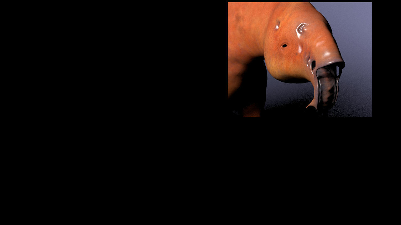
When you use the camera view (numeric keypad 6), areas of the viewport that are outside the render area will be colored with the overlay color chosen in Display Options (D). You can have horizontal bars showing the exclusion or they can be vertical bars, depending on the frame aspect of the render you are making (in the image below demonstrating this we are using a monitor with a resolution of 1920x1080 and rendering an image at 1280x720).
Furthermore you will be able to show safe areas for overscan and underscan displays by turning on the Show Safe Areas switch in the Display Options (D). You will also have a grid displayed to allow you to better divide up the frame by selecting Show Field Chart.
If you are using a view other than the camera view, you will see the camera represented on-screen together with a pyramid showing its field of view. This pyramid is only shown when the camera is the selected item.


Left Camera view, Right: Camera View with Safe Areas and Field Chart

Perspective view
If you are using an orthogonal projection and you have Show Fog Circles option switched on in the GL tab of Preferences (O), you will be able to see the area around the camera affected by fog. If you press Ctrl- P and choose a fog type from the Volumetrics tab while in a top view mode, for example, you will be able to see circles around the camera indicating a minimum and maximum fog radius around the camera.
Top view, with Fog circles
Rendering a Limited Region
You can render a limited rectangular region of your scene if you only wish to test your work, rather than taking the time to render a full image. Limited Regions are also useful if you would like an accurate representation of your final frame in VPR, rather than the whole viewport. As an added benefit, it will speed up rendering, not having to render pixels that will not be in the final frame. Simply hit the L key and you will see that a dotted line will surround the renderable area of the frame. You can change the size and shape of this area by clicking and dragging the left mouse button on one of the dotted lines that surround the area.


Above: What Layout looks like, Left: Render Limited Region Borders, Right: Render Limited Region No Borders
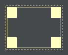
Borders, no Borders
There are two different types of limited region that you can use, either with or without borders and you cycle through these choices by repeatedly hitting the L key or by choosing the drop down menu in the Render Globals window. The difference between a limited region with a border and one without it is the fact that a limited region with a border puts your limited region on a black page the size of a full render, whereas a limited region without borders will just render the shape you desire as the full image. The frame aspect ratio in Camera Properties will remain at the aspect ratio for a full frame, but all other options, such as antialiasing and Masks still apply.
The limited region with border allows you to “patch” only a segment of a frame, rather than having to re-render the whole frame for re-compositing. This can be a major time-saver.
Memory Considerations
Limited Region allocates only enough memory to render the horizontal limited region area. If you stitch parts of an image together, you can effectively render images that are much larger than those you could render one pass. This is especially useful for high-resolution print images or in low memory situations. However, note that some post-processing filters require a full-sized image. In such cases, you may be able to apply those filters to the “stitched” image in an additional step. The way to do this is to take your final rendered image and save it to disk. Then clear your scene - or better yet, quit and restart LightWave – and load this image into an empty scene. Make it the camera backdrop and add whichever post-process filter you wish to use, and then render again. Since you aren’t rendering all the objects, textures, Image Maps, etc., the memory requirements will be a lot lower.
If aliasing (the stepping effect on diagonal lines seen when image resolution isn’t high enough) is the crime, then anti-aliasing is the cure. Aliasing occurs because a pixel is rectangular in shape which means that there will always be a jagged effect with anything other than rectangular shapes. This effect can be reduced by working at high resolutions but cannot be removed. All image-processing programs, including LightWave, employ a device called anti-aliasing in order to reduce this stair-stepping effect. It compares the RGB values of two neighboring edge pixels and adds an average-valued pixel between them. This fools the eye into seeing a smooth line.
Anti-Aliasing
Overview of Controls
Shading Samples
To shade a pixel, LightWave needs to gather information about it. Shading samples define how many rays are fired to that pixel to determine its overall shading. Every pixel in the rendered image is hit by an initial ray fired from the camera; when a ‘hit’ occurs. If you have Shading Samples higher than 1, more rays are fired. The amount fired is set by the number of Shading Samples, so if you set it to 4, that many rays are fired. This process is repeated for each pixel if Minimum Samples is higher than 1, and is repeated as many times as set by the Maximum Samples in Camera Properties.
Lower numbers render faster at the expense of quality or noise in the image, the reverse is true for higher numbers.
Motion Effects
Rolling Shutter and Motion Blur Bias

LightWave 11.5 added a rolling shutter to the Motion Effects settings for the camera. Working with footage that has been tracked in applications like Syntheyes can sync badly with CG-generated footage if the camera used is CMOS-based (CCD-based cameras have no problem with rolling shutter). A rolling shutter offset helps with such issues and ensures that your tracked footage matches the CG you create in LightWave.
- Subframes - controls the number of subframes used to create the motion blur streaks. For objects that are moving along curves, the more subframes, the smoother the streaks will appear. Motion is calculated as a series of linear steps currently. The default is 20 subframes to match previous versions. With the addition of multi-step deformation blur, calculating all the vertex positions 20 times a frame may be too slow for VPR. In addition, it is possible that users may need more than 20 subframes for animations with a great deal of motion.
- Shutter Open - defines the time offset for the start of the render. If the Blur Length is set to 50%, a Shutter Open value of -25% will center the motion blur for each frame.
This is because a Blur Length of 50% is a half-frame’s worth of blur between the current frame and the next frame. A Shutter Open value of -25% would start the render a quarter-frame before the current frame. The 50% Blur Length would then carry the render past the current frame to end at a quarter-frame past the current frame, centering the motion blur. - Rolling Shutter - mimics the shearing distortion of a rolling shutter. Each horizontal line in the frame is progressively shifted forward in time, up to a maximum of a single frame’s worth on the bottom or top line. The positive or negative value of Shutter Skew determines whether the top or bottom get sheared forwards in time. At 100%, the bottom of the frame will show the positions of everything as they appear on the next frame. At -100%, the top of the frame shows the positions from the next frame.