Graph Editor Toolbar
The Toolbar contains a slew of commands for the Graph Editor. Many of these are also available on the various Curve Bin and Curve Edit Window pop-up menus, described later.
Toolbar Selection Menu
The Selection menu contains commands that affect curves in the Curve Bin.

- Add Layout Selected (default keyboard shortcut L) - This command will add the channels for the currently selected item(s) in Layout to the Channel Bin.
- Get Layout Selected (default keyboard shortcut Shift G) - This command will replace the contents of the Channel Bin with the channels for the currently selected item(s) in Layout.
- Clear Unselected Channels (default keyboard shortcut X) - This command will remove any unselected curves from the Channel Bin.
- Clear Channel Bin (default keyboard shortcut Shift X) - This command will empty the Channel Bin.
- Remove Channel from Bin (default keyboard shortcut Shift D) - This command will remove all selected curves from the Channel Bin.
- Invert Channel Section (default keyboard shortcut I) - This command will invert the selection state of curves in the Channel Bin.
- Select All Curves in Bin (default keyboard shortcut Ctrl Up) - This command selects all of the curves in the Channel Bin.
- Reset Bin Selection (default keyboard shortcut Ctrl Down) - This command leaves only the first curve in the Channel Bin selected.
- Filter Curves (default keyboard shortcut W) - Use this command to filter out channels from the Channel Bin that do not match a pattern. The pattern is case sensitive. *.Position.* would remove any channel that wasn’t a Position channel. You could use *.Y to show only Y channels.
- Filter Position Channels (default keyboard shortcut !) - Use this to filter out everything but Position channels from the Channel Bin.
- Filter Rotation Channels (default keyboard shortcut @) - Use this to filter out everything but Rotation channels from the Channel Bin.
- Filter Scale Channels (default keyboard shortcut #) - Use this to filter out everything but Scale channels from the Channel Bin.
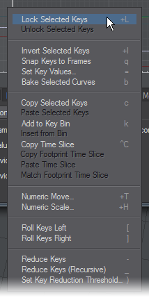
Toolbar Keys Menu
The Keys menu contains commands that manipulate the selection, creation, deletion, frame setting, and value of keys.

- Create Key (default keyboard shortcut Return) - This allows you to create a key, Layout-style. A dialog will appear where you can enter the Frame and Value.
- Delete Selected Keys (default keyboard shortcut Delete) - This command will delete any selected keys.
- Lock Selected Keys (default keyboard shortcut Shift L) - This locks the selected keys so they are uneditable. Locked keys are grey.
- Unlock Selected Keys (default keyboard shortcut Shift K) - Unlocks selected keys.
- Invert Selected Keys (default keyboard shortcut Shift I) - This flips the order of selected keys in time.
- Snap Keys to Frames (default keyboard shortcut Q) - This command causes every selected key that falls on a fractional frame to snap to the nearest whole frame.
- Set Key Values (default keyboard shortcut =) - This command will bring up a dialog where you can enter a new Value for the selected keys.
- Bake Selected Curves (default keyboard shortcut B) - This “bakes” the state of selected curves by creating keys at every frame. Curves do not necessarily need to be affected by a Modifier, but their effects will be taken into account.
- Copy Time Slice (default keyboard shortcut Ctrl C) - You can copy values of selected curves at the current frame (even if there are no existing source keys) and paste them elsewhere. This command will copy the values. These values may be pasted at any frame with Paste Time Slice, but only onto the same curve(s).
- Copy Footprint Time Slice (default keyboard shortcut Ctrl X) - This works like Copy Time Slice, but uses the value(s) from the curve’s footprint instead of the actual curve. Use Paste Time Slice to paste.
- Paste Time Slice (default keyboard shortcut Ctrl V) - Pastes in values copied with Copy Time Slice or Copy Footprint Time Slice at the current frame. Keys will be created (or modified, if they already exist) at the new frame with the new values.
- Match Footprint Time Slice (default keyboard shortcut Ctrl B) - This creates a key on the curve that matches the footprint value at the current time. Essentially, it is the same as doing a Copy Footprint Time Slice operation and immediate paste.
- Copy Selected Keys (default keyboard shortcut C) - This copies selected keys to a memory buffer. To paste the buffer, you must have your mouse pointer over a curve and use the Paste Keys command on the Curve Edit Window pop-up menu (Ctrl+Shift+LMB), discussed later.
- Add to Key Bin (default keyboard shortcut K) - This creates a named set of keys that you can insert into a curve later. To paste the set, you must have your mouse pointer over a curve and use the Insert From Bin item on the Curve Edit Window pop-up menu (Ctrl+Shift+LMB), discussed later.
- Numeric Move (default keyboard shortcut Shift T) - With this command, you can shift the selected keys. Frame Offset is the number of frames to use for the shift. Value Offset is a number to add to or subtract from the value for each keyframe.
- Numeric Scale (default keyboard shortcut Shift H) - This command lets you scale the key times and values for selected keys. A Time Scale Factor of 1 means no change. A value of 2 would double the time, and .5 would halve it. The Time Scale Origin is the center of the scaling. Thus, if you place this at one selected key, the scaling will happen around it and not affect that particular key. This setting uses the units displayed on the graph. Value Scale Factor and Value Scale Origin work similarly, except they change the selected key values.
- Roll Keys Left (default keyboard shortcut [) - Shifts the values of the selected keys to the left without affecting their time. This command works only with contiguously selected keys.
- Roll Keys Right (default keyboard shortcut ]) - Shifts the values of the selected keys to the right without affecting their time. This command works only with contiguously selected keys.
- Reduce Keys (default keyboard shortcut - ) - The Reduce functions let you remove consecutive keys that are within a certain threshold value of one another. The threshold is set by selecting Set Key Reduction Threshold.
There are two modes: Reduce Keys and Reduce Keys ( Recursive), whose default keyboard shortcut is _. As an example, assume consecutive keys A B C D E all have values within the threshold. Choosing Reduce Keys would remove keys leaving A C E. Selecting Reduce Keys again would leave A E, and a final Reduce Keys would leave only A. Reduce Keys (Recursive) would go directly from A B C D E to A in one step.
If you set the threshold to a negative number, Reduce Keys will eliminate every other key. Reduce Keys (Recursive) will remove all but the first key.
Toolbar Footprints Menu
The Footprints feature lets you create an imprint of the current curve(s) to use as a reference and as a state you can revert back to.

- Leave Footprint (default keyboard shortcut Shift F) - Creates the imprint that will be visible as a shade of the real curve’s color (once you make a change).
- Pickup Footprint (default keyboard shortcut Shift R) - Erases the footprint for the current curve(s).
- Backtrack Footprint (default keyboard shortcut Shift B) - Will restore the curve to its footprinted state.
Toolbar Autofit Menu
This group of commands affect the range of frames and values shown in the Curve Edit Window.

- Autofit (default keyboard shortcut A) - You can automatically scale the graph display to show all of the selected curves with this command.
- Autofit Selected (default keyboard shortcut Shift A) - You can automatically scale the graph display to show all of the selected keys with this command.
- Autofit By Type (default keyboard shortcut Ctrl A) - Autofit By Type will scale the graph to fit the values for the primary selected curve’s type (i.e. position, rotation, scale, and so on).
- Fit Values By Type (default keyboard shortcut Ctrl F) - This works like Autofit By Type, but only scales the graph vertically, retaining the current frame range.
Toolbar Display Menu
The Display menu contains commands that affect the graph display, as well as global options.

- Numeric Limits (default keyboard shortcut Shift N) - This will display a small dialog. The Min Frame and Max Frame values set the range of frames you want to see on the graph. The Min Value determines the value of the bottom boundary of the graph and the Max Value sets the upper boundary.
- Go To Frame (default keyboard shortcut F) - This action sets the current frame to the entered value. It also centers the Curve Edit Window around that frame.
- Center Graph (default keyboard shortcut G) - Centers the graph on the current mouse position.
- Reset Graph (default keyboard shortcut /) - This simply resets the graph to default frame and value ranges.
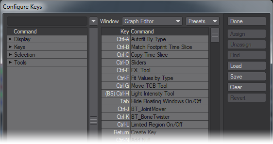
- Edit Keyboard Shortcuts (default keyboard shortcut Alt F9) - This command will bring up the standard Configure Keys Panel. However, it will list shortcuts for the Graph Editor. (Note that the Window pop-up menu will be set to Graph Editor.)
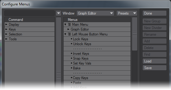
- Edit Menu Layout (default keyboard shortcut Alt F10) - The Graph Editor has its own set of menus. These can be customized using the normal Configuring Menus Panel. (Note that you are editing the Graph Editor menus when Graph Editor is selected in the Window pop-up menu on the Configuring Menus Panel.)
Beneath the Main Menu group is the Graph Editor group. This is the group used for the Graph Editor’s toolbar. It can contain its own group for pull-down style menus. In the Popup Menu group are the commands that will appear when you press Ctrl+Shift+ LMB over the Curve Edit window.
- Insert Overwrites Keys (default keyboard shortcut `) - Normally, when you paste in more than one key, existing keys may be shifted over. Enable this option to replace the paste range and not shift over keys.
- Filter Static Envelopes (default keyboard shortcut numpad 1) - This option will keep envelopes that have fewer than two keys from being displayed in the Channel Bin when selecting groups (both from the scene list, as well as from other Layout panels.)
- Large Autosize Margins (default keyboard shortcut numpad 2) - This option will add an extra amount of outside space when you use autofit commands.
- Allow Fractional Keyframes (default keyboard shortcut numpad 3) - This option keeps frame adjustments to whole numbers. This is linked to Layout’s Allow Fractional Current Frame setting (General Options Tab of the Preferences Panel).
- Lazy Layout Update (default keyboard shortcut numpad 4) - When active, the Graph Editor will not update in Layout until after you release the mouse button. This can allow smoother adjustments in complex situations. When inactive, Layout will update as you make adjustments.
- Track Layout Time (default keyboard shortcut numpad 5) - This option will scroll the Curve Edit window to keep the frame slider centerd. This is useful for watching the curves scroll by as Layout is playing.
- Allow Passthrough Keys (default keyboard shortcut numpad 6) - This option lets you drag keys through each other in time. Normally, you stop at a neighboring key.
- Lock Motion Keys in Time (default keyboard shortcut numpad 7) - This option causes keys to be created for all motion channels of the selected channel(s). Only Position, Rotation and Scale channels are affected. For example, Position.Y, Position.Z, Rotation.H, etc. would all be affected if Position.X was selected.)
- Move No Keys Sel (default keyboard shortcut numpad 8) - By default, if no keys are selected, no editing will occur when using tools like Move or Stretch. Activate this option to change this so that all keys are considered selected when none are selected (like in Modeler).
- Track Item Selections (default keyboard shortcut numpad 9) - This is a mode that will automatically bring the channels for the currently selected Layout item into the Graph Editor.
- Fit Values when Selected (default keyboard shortcut numpad 0) - When this option is active, your view will automatically fit the values of the selected curve. This will not affect the visible range of frames, however.
- Show Modifiers - Activate this to always make the modified curve (i.e., after the effects of motion Modifier plugins) visible as a dotted line.
- Show Tangents - This command will activate or deactivate tangent handle display.
- Center Speed Curves - Keeps the speed curves in the center of the Graph Editor display.
- Antialias Curves - This command will activate or deactivate the feature that smooths the display of curves.
If you are working with a lot of curves and keys, turning off the Antialias Curves and Show Tangents options can help speed up display refreshing.
- Show Key Info - This turns the pop-up display of key information off or on. This appears when your mouse pointer is directly over a key.
- Hide Background Curves - Normally, non-selected curves in the Curve Bin are visible in the graph. This display option will toggle their visibility state.
- Large Keyframe Points - Activate this option to increase the display size of keys.
- Custom Point Color - This turns on the user-defined (unselected) point color. Selected points are always yellow.
- Collapse/Show All (default keyboard shortcut F5) - This collapses or shows the Tabs and Trees areas of the Graph Editor.
- Collapse/Show Tabs (default keyboard shortcut F6) - This is the same as clicking the Collapse Tabs button.
- Collapse/Show Trees (default keyboard shortcut F7) - This is the same as clicking the Collapse Trees button.
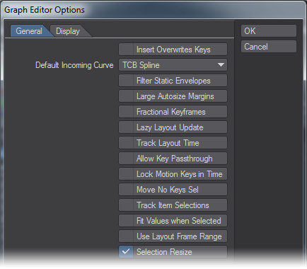
Graph Editor Options
(default keyboard shortcut O)

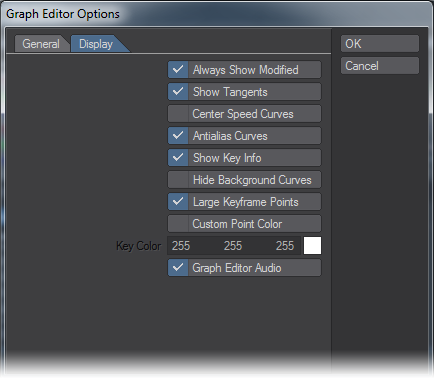
Most of the options on this panel can also be set from the Display menu and have been described previously. There are a few that can only be set here, however. On the General Tab, you can change the Default Incoming Curve. On the Display Tab, you can set the color used when the Custom Point Color option is active.
Undo

Undo Last Action (default keyboard shortcut Ctrl Z). Use this command for a single level undo/redo of the last edit.
Also see the Footprints feature
Cancel Changes
(default keyboard shortcut Shift U)

This command restores all envelopes to their state at the time the Graph Editor Panel was last activated (i.e., making it the top window).
Channel Bin Pop-up Menu
The Channel Bin has a pop-up menu that appears when you right-click a curve:
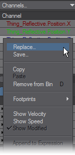
- Replace… - Used to load a curve from a file
- Save… - Saves a single curve to a file
- Copy - Copies the curve under your mouse pointer when you open the menu to the curve memory buffer
- Paste - Pastes the curve stored in the memory buffer. Your mouse pointer must be over the curve you wish to replace before you open the menu
- Remove from Bin - Removes the selected curve(s) from the Channel Bin
- Footprints - See Footprints
- Show Velocity - Adds a non-editable background curve representing the velocity of the selected curve. Velocity is defined as the time rate of change for a single curve including a vector. In other words, a velocity curve describes how much the value of the current single channel changed at that time
- Show Speed - Adds a non-editable background curve representing the speed of the current curve. Speed is defined as the magnitude of the velocity vector. This means the Speed curve represents the time rate of change of all three position, rotation, or scale curves
- Show Modified - If the Show Modifiers option (Display menu) is active and your curve is being modified, from a modifier plugin for instance, this will let you see the actual modified motion curve
- Append to Expression - This command will place the selected channel in the expression field. This is handy and will save you from having to type out channel names when creating expressions
Curve Edit Window Pop-up Menu
Another pop-up menu is available when you work in the Curve Edit Window. It appears when you Ctrl+Shift+LMB click over the graph. This gives you quick access to many commonly used commands.
Most of the commands have been discussed; however, some only appear on this menu because they require your mouse pointer to be directly over a curve.
- Copy Selected Keys - This copies selected keys to a memory buffer
- Paste Keys - Inserts the keys stored in a memory buffer with the Copy Selected Keys command- existing keys may be moved over if the buffer has multiple keys. Your mouse pointer must be over the pasting point on a curve before opening the menu (pointer will highlight)
- Add to Key Bin - Creates named set of keys that you can insert into a curve later
- Insert - Works like Paste Keys, but gets data from a specified key set
- Options - Displays the Graph Editor Options Panel
Key Pop-up Menu
Another contextual pop-up is available when you work in the Curve Edit Window. It appears when you right-click directly over a key - the operations affect that key only.
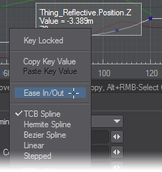
- Key Locked - Locks/unlocks the key so it is uneditable; locked keys are gray when selected, black when not
- Copy Key Value - Copies the key value to memory buffer
- Paste Key Value - Pastes the value stored in memory to the key
- Ease In/Out - Sets the Incoming Curve for the key to TCB Spline and sets the Tension to 1
- Incoming Curves - Quickly change the Incoming Curve type for the key by selecting it from the list at the bottom of the menu
Other customizable menus will appear when you Ctrl+Shift+RMB and Ctrl+Shift+MMB .
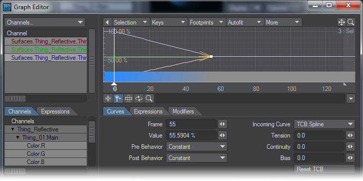
Graph Editor - Editing Color Channels
You can also animate color channels. If you add an envelope for, say, a surface color, you can edit the related RGB channels on the Graph Editor.
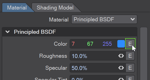
Clicking the Color Envelope Button in the Surface Editor
When a color channel is selected in the Channel Bin, a color bar will appear at the bottom of the graph. The bar shows you the color for the combined red, green, and blue values at any particular point in time-even if you don’t have all three color components in the bin.
You can adjust any color channel beyond the normal maximum and minimum - creating a high dynamic range color. This may have no visible effect on the color bar, but could affect how the color is interpreted by other factors.
You can use a color requester to set the key values by right-clicking on a key and selecting Open Color Picker. Note that the selected color will only set the color component for the selected channel(s). If other channels are selected, keys will be created as needed.
Graph Editor: Curves Tab
The Curves Tab in the Curve Controls area contains specific values for a selected key(s). The Frame field contains the frame number and the Value field holds the related value.

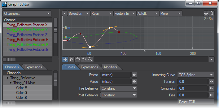
Multiple Values
If you select multiple keys, input fields will show (mixed) if the keys have different settings. You can still edit the fields, which will change all selected keys to match the entered value. You can use this method to flatten a portion of a curve(s) or to match key times across multiple curves.
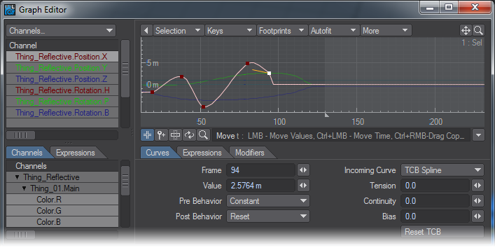
Pre and Post Behaviors
The Pre Behavior setting determines what happens before the first keyframe. The Post Behaviour determines what happens after the last keyframe. The available settings are:
With Reset, the motion value is reset to zero.
With Constant, the values beyond the ends are constant, that is, equal to the first or last keyframe value.

With Repeat, the motion repeats from the first to last keyframe.

With Oscillate, the motion is mirrored over and over.

With Offset Repeat, the motion repeats, but it is offset by the difference between the first and last keyframe values.

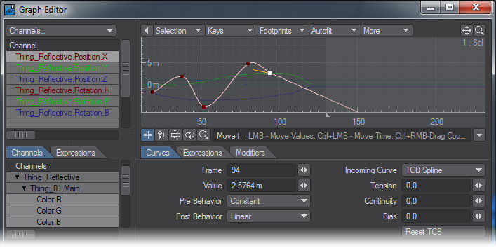
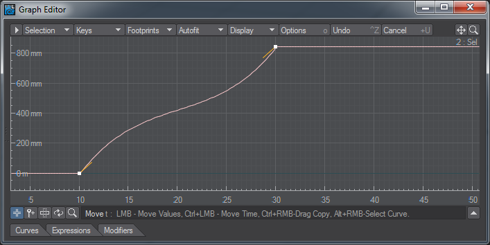
With Linear, the curve receives a linear angle consistent with the angle at the start or end points.
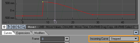
Incoming Curves
The type of curve that precedes a key can be set using the Incoming Curve pop-up menu.
TCB Spline
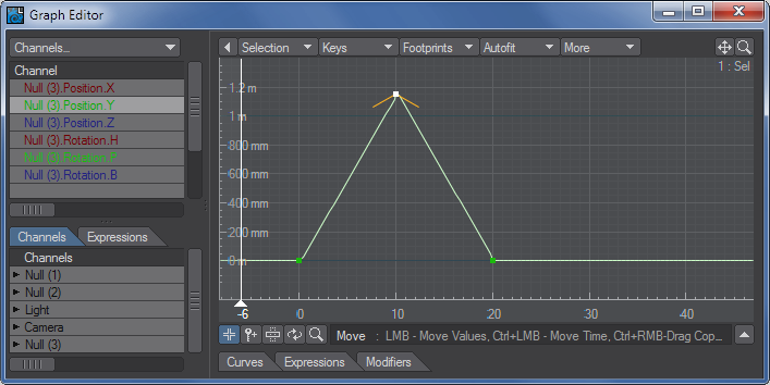
TCB Spline (Tension, Continuity and Bias) curves have three controls that determine the shape of a curve as it passes through a key.
Tension causes an object in motion to slow down, or move a little bit less in each frame, as it nears the keyframe, and to accelerate as it passes the keyframe (-1 = low tension, 0 = normal tension, 1 = high tension). Without Tension (i.e., value of 0), the object would pass through the keyframe position at a constant speed. Positive values slow an item through a keyframe (ease-in) while negative values speed it up (ease-out).
Tension –1
Tension 0
Tension 1
A high Tension value (1.0) is often used at the end of a flying logo move in order to make the logo come to a gradual stop. High Tension at the beginning of this move would make the logo start slowly, while a negative value would make the logo start quickly.
If you right-click on a key, choosing Ease In/Out from the pop-up menu will set the Tension to 1 for all selected keys using TCB Spline.
Continuity accentuates a break or change in an object’s graph (-1 = sharp , 0 = normal , 1 = smooth). Negative Continuity gives a sharper transition in the spline path at a keyframe, while positive Continuity gives a broader transition (sometimes over-continuous) through a keyframe. Negative Continuity is usually used to replicate a sharp change in motion such as that of a falling ball striking a floor and quickly reversing direction.
Continuity –1

Continuity 0
Continuity 1
You would rarely want to use a positive continuity - this will cause an object to overcompensate as it passes through the keyframe and appear to stutter or roller coaster at the frame.
Bias determines whether an item’s spline path leans to one side of a keyframe or the other (-1 = more slack incoming, 0 = equal slack, 1 = more slack outgoing). You accomplish this effect by moving the slack in the spline path to one side or the other of a keyframe. This serves to accentuate motion - the incoming motion by undershooting the keyframe and creating a feeling of anticipation, or the outgoing motion by overshooting the keyframe. For example, a racing car moving through a turn could use either a negative or a positive Bias setting to a) anticipate the turn with a negative Bias, or b) overshoot the turn with a positive Bias.
Negative Bias values place the slack before the keyframe while positive Bias values place it after the keyframe.
Bias -1
Bias 0
Bias 1
Interactive TCB Adjustments
You can interactively adjust TCB keys with your mouse. Simply press F1 for tension, F2 for continuity, or F3 for bias and then drag your mouse left to decrease or right to increase the value. You will see a small indicator in the lower-left corner of the graph.
This only works in the Move Edit Mode and for the first mouse drag. The tool stops when you release the mouse button.
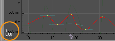
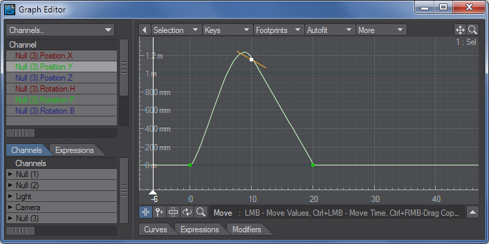
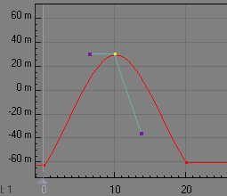
Hermite Spline
If you use Hermite Spline, a tangent control handle will appear, emanating left from the key. This type of curve is an extension of the standard TCB Spline, but allows a wider range of results. Drag the handle (at the end) up or down to change the angle of the tangent and thus the shape of the curve.
Note that TCB Splines generally limit you to more realistic results.
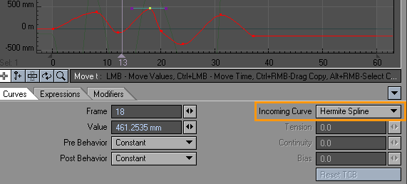
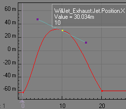
Bezier Spline
Splines using Bezier Spline operate like bezier curves do in many industry-standard paint and illustration packages. When you create a key, you must drag before releasing your mouse button to edit the handles. Otherwise, bezier keys have handles that coincide with the key. For an existing key, select it and then click-drag on it to pull out the handles.
Drag the handles to change the angle of the tangent and thus the shape of the curve. If you are curious, Bezier splines are indeed a variant of Hermite splines, and thus the results will be very similar.
Bezier curves were developed by Pierre Bézier for designing Renault automobile bodies.
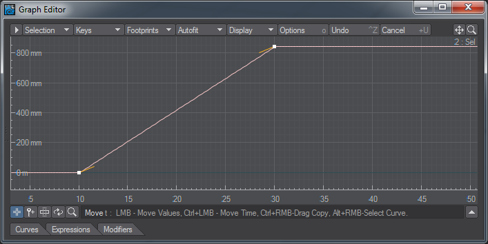
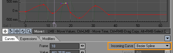
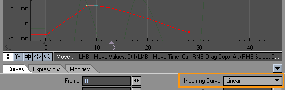
Linear
Linear removes the gradual, smooth nature of a spline curve change and replaces it with more direct, sudden change. Linear affects the changes between the current keyframe to the previous keyframe only. By turning Linear on or off at different keyframes, graphs may contain both gradual and sudden changes.
Stepped Transition
Stepped transition holds the preceding keyframe value and then abruptly jumps to the next keyframe value at that frame.
Dual-handled Control Points
When a Hermite or Bezier (incoming curve) key is followed by another key with the same incoming curve type, the (outgoing) tangent on the right side will affect the outgoing curve as well. Normally, the outgoing tangent will be unified with the incoming tangent. That is, they will operate as though there is only one tangent.
You can break the tangents, that is, make them operate separately by holding the Alt key and then dragging either side.
To reunite the tangents, just double-click on either control handle. The opposite side will line back up.
Graph Editor: Expressions Tab
Expressions are detailed here: Expressions
Graph Editor: Modifier Tab
Channel Motion Modifiers
Channel motion modifiers are added on the Modifiers Tab of the Graph Editor. These modifiers control the motion at the channel level, as opposed to the (scene) item level, where motion is handled by item motion modifiers.
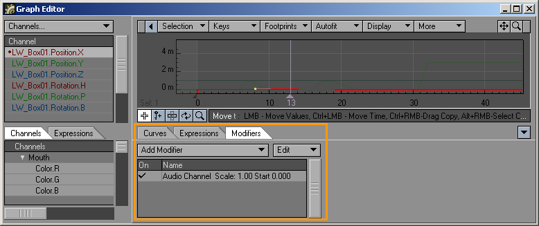
To use a channel motion modifier, select the target curve in the Graph Editor’s Channel Bin. Then select the modifier from the Add Modifier pop-up menu on the Modifier Tab. Once added, click on its name in the list to access its settings, if any. Channels with modifiers will have a small dot to the left of their names in the Channel Bin.
Modifiers that do not have an explicit additive option are generally additive in nature.
Also see the MasterChannel Scene Master plugins. This lets you create custom user-defined channels.
AudioChannel
The AudioChannel modifier modifies a curve based on an audio file.
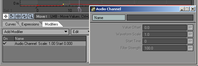
Click the Name button to select the audio file you want to use. The Value Offset lets you move the entire motion up or down. (The units are the ones used on the graph.) Waveform Scale is a multiplier. Thus, a value of 1 will have no effect. A value of 2 will double the values of the effect and .5 will halve it. Use the Start Time to enter a frame number when the audio should begin. The Filter Strength value will determine the sampling frequency used to convert the audio into a curve. A higher value will cause the curve to more closely follow the contours of the audio’s sound wave.
BoosterLink
IK Booster Link can be used to link a channel from one controller to a channel in another controller. The Linked controller can be driven by the referenced control. This is very similar to how expressions can be used without writing any expressions.
See the IK Booster section for more information.
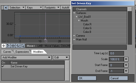
ChannelFollower
Using Channel Follower (aka Set Driven Key) is similar to parenting an object to another, except that you have control over which motion channels you wish to inherit. You can also modify and delay the inherited value. Moreover, the motion can be inherited from the camera, a light, a bone, or any object in the scene.
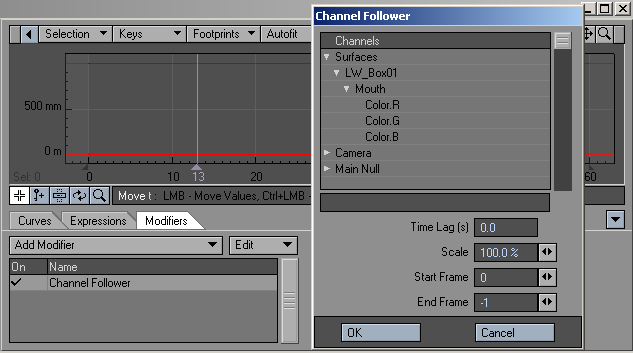
Select the channel you wish to follow from the Channels list window.
The amount of seconds entered into the Time Lag field is added to the current time. This number may be negative.
The value can be scaled by inputting a factor other than 100% in the corresponding Scale field.
The Start Frame and End Frame parameters specify when the modifier is applied.
Cycler
This is a channel-oriented version of the Cyclist item motion modifier.
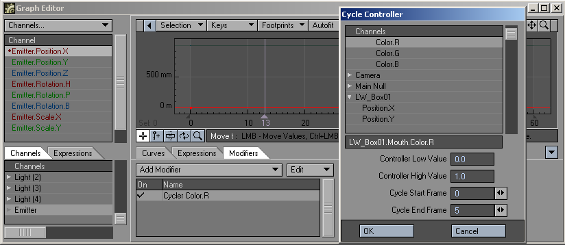
Select the controlling channel in the Channels list window. The Controller Low Value and Controller High Value settings define how much change is required to equal one full animation cycle. The unit of measure for this parameter depends on the selected control channel.
Expressions
Expressions are an advanced LightWave 3D feature that uses mathematical formulas to modify the value of any animation channel. Expressions let you make the motion of scene items dependent on other item motions or factors in a scene. You could, for example, force an object to stay between two other objects, keep feet from going through the floor, or even control the entire posture of a character based on its feet! The possibilities are endless.
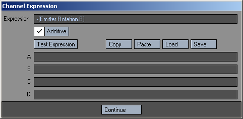
The Expressions Panel has four buttons: Copy, Paste, Load and Save. The Copy and Paste functions work on a per-screen basis - if you type in your full expression, you may click on Copy, open another channel up, and then click on Paste and the entire expression is pasted in, including scratch variables. Click on Save if you create an expression that you want to use again in the future. You will then be able to load it into other channels at your convenience.
The A, B, C, and D fields are scratch variables for the expressions. Each of these can have an expression, which is evaluated before the main expression. This means that the main expression can use the variable A, B, C, and D for some other calculated value. The scratch variables are evaluated in alphabetical order, so B can use A, C can refer to A and B, and the D expression can contain A, B, and C.
Scratch variables are useful both for breaking up massive expressions and for logically separating the functional elements of an expression. For example, driving a ball’s pitch based on its Z-distance can simulate rolling if the ball rotates once for every pi*diameter it moves. This expression (pitch = pi*Z/Diameter) fits on a line, but you need to include the model’s diameter. If you apply it to another ball, the expression must change. If you include the diameter in A, then changing the expression is more obvious; when you scale up the ball, A can be more complex.
FX_Clink
These channel and motion modifiers let children of a parent, which uses FX_Link, respect the parent’s ‘time shift’ setting. This modifier has no interface.
FX_Link
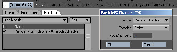
The FX_Link channel modifier has two functions. First, it can be used to dissolve out the object when the particles die.
Dissolving an object based on particle life
- Open the Object Properties Panel for the object to be dissolved. (You’ll also need an existing emitter controller.)
- On the Rendering Tab, click the Object Dissolve Envelope button. This adds a Dissolve channel for the object and opens the Graph Editor.
- On the Modifiers Tab of the Graph Editor, add the FX_Link modifier. Open its Options Panel by double-clicking its name in the list after it has been added.
- Set the mode to Particles dissolve and select the emitter from the Particles pop-up menu. Enter the particle number in the Node/numbers field; 0 is the first emitted.
- Click OK. When that particle dies, the object will be dissolved to 100%.
FX_Link can also be used to vary a channel based on the number of particles at the emitter
Controlling a channel based on the number of particles
- Open the Graph Editor and select the desired channel in the Curve bin.
- On the Modifiers Tab of the Graph Editor, add the FX_Link modifier. Open its Options Panel by double-clicking its name in the list after it has been added.
- Set the mode to Particles numbers and select the emitter from the Particles pop-up menu.
- Click OK to close the panel and play your scene. The channel you selected will be changed based on the number of particles in that particular frame.You can scale the value by entering a number in the Node/numbers field. The number of particles will be divided by this value.
LScript and LScript/RT
These commands allow you to load a channel-oriented LScript.
MM (Motion Mixer) Channel Driver
When an X Channel is added to a Motion Mixer Actor, this modifier is automatically added. Removing X Channels from an actor is achieved by either using the Remove Items entry in the Actor Menu, clearing the item from the scene, or manually removing the MM_ChannelDriver modifier on the Graph Editor.
For more information see Motion Mixer documentation
NoisyChannel
This modifier randomizes a channel.
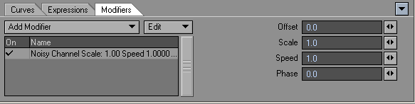
The Offset lets you move the entire motion up or down. (The units are the ones used on the graph.) The Scale parameter multiplies the noise amount added in to the channel, so a factor of 1 will have a noise effect, a factor of 0 will have no effect, 2 will double the effect, .5 would halve it, and so on. Speed is the rate of change of the noise, basically like a texture velocity. Phase shifts the effect in time.
The formula is:
channel value = old value + scale * fractal noise(phase + speed*time )
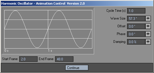
Oscillator
This is a channel-oriented version of the Oscillator item motion modifier. The channel is determined by which channel the modifier is added to in the Graph Editor. The effect is always additive.
Proximity
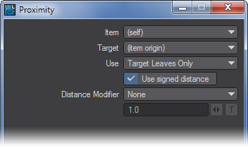
The Proximity plugin is implemented as a channel modifier plugin. It can be added as a channel modifier to any channel. This can be done either directly through the graph editor, or via an envelope for a parameter.
- Source (item the plugin is applied to):- Proximity computes the distance between the position of a source item and one or more target items or meshes. This setting is used to set the source item.
When set to “(self)”, Proximity will use the item to which the channel being modified is attached. If the channel is not attached to an item, Proximity won’t do anything if the source is set to “(self)”. - Target :- Sets the target to which the distance from the source is measured. The target may be any item, with or without a mesh. If an item has a mesh, the shortest distance between the source position and the mesh will be computed. If an item does not have a mesh (such as a null, a camera, or a light) the position of the item’s origin is used.
- Use ( How the channel will be effected) -
- Target Only - The distance from the source to the target is used. If the target has a mesh, the distance to the nearest point on the mesh is computed, otherwise the distance from the source to the target origin is used.
- Target and Decendants - Like “Target Only”, but any items parented to the target (and the items parented to those items, etc.) are considered as well. The nearest distance found for all items is used.
- Target Leaves Only - Like “Target & Descendents”, but only the leaf items are used. The leaf items are those items in the tree which have no children.
- Target Leaves as Line - Like “Target Leaves Only”, but the positions of leaf items with a common parent are considered as the vertices of a polyline. The shortest distance between the source position and the polyline is used.
- Signed Distance :- When computing the distance from a source to a mesh, the distance can be either signed or unsigned. When signed distance is turned on, the distance will be negative if the source is below the surface of the mesh. Otherwise the distance will always be positive.
- Distance Modfier :- remap the distance calculation
- None :- The channel value is set equal to the computed distance.
- Scale :- The distance is scaled by the given factor to give the channel value.
- Remap :- Arbitrarily change the distance to a channel value. Typically this is used in combination with a gradient texture or an expression.
All the distance modifiers can be enveloped, textured, etc. for full control of the effect.
Sticky.rMeshDistance: Distance of the sticky item to the nearest point on a sticky surfaceDistance to mesh: Distance of the sticky item to the nearest point on a sticky surface
Python
Will load a Python script, like the LScript modifier above.
Python Noisy Channel
Example Python code that you can play with for your own scripts, the source can be found in LightWave/Support/plugins/scripts/Python/Layout/ChannelFilter.
RelChanneler
Open the Relativity Channeler Expression Module.
SetDrivenKey
Using SetDrivenKey (aka ChannelFollower) is similar to parenting an object to another, except you have control over which motion channels you wish to inherit. You can also modify and delay the inherited value. Moreover, the motion can be inherited from the camera, a light, a bone, or any object in the scene.
Select the channel you wish to follow in the Channels list window.
The amount of seconds entered into the Time Lag field is added to the current time. This number may be negative.
The value can be scaled by inputting a factor other than 100% in the corresponding Scale field.
The Start Frame and End Frame parameters specify when the modifier is applied.
Textured Channel
This is a channel-oriented version of the Texture Motion item motion modifier. It works exactly the same except that you apply it directly to the channel you wish to modify.
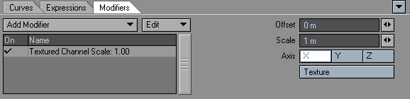
Since textures are three dimensional, particularly procedurals, use the Axis setting to use the X, Y or Z of the texture. (Note: The differences between the Axis selection can be subtle.) You can also move the texture with the Offset setting and change the size of the texture using the Scale setting.
Virtual Studio Trait
This is a modifier to add to an object you wish to control inside Virtual Studio. See the Virtual Studio section starting page PDF_LINK for more details.