Animating
Now that you have reviewed cameras, lights and objects in the Layout section, it’s time to discuss animation.
Keyframing
The way to tell the computer where an object - be it camera, models or lights - is at any given point is to use keyframes. Keyframes fix an object’s location, rotation and scale for a given moment in time. Setting one at the start of your animation and one at the end means that LightWave will automatically interpolate between them for the duration of the animation. In fact it will create these in-between frames, called tweens, between every keyframe resulting in a fluid animation. To get you started, let’s create a piece of the easiest animation possible.
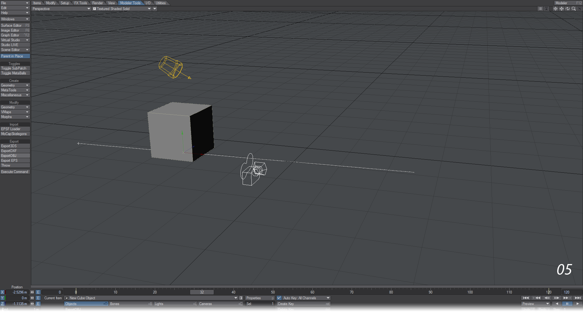
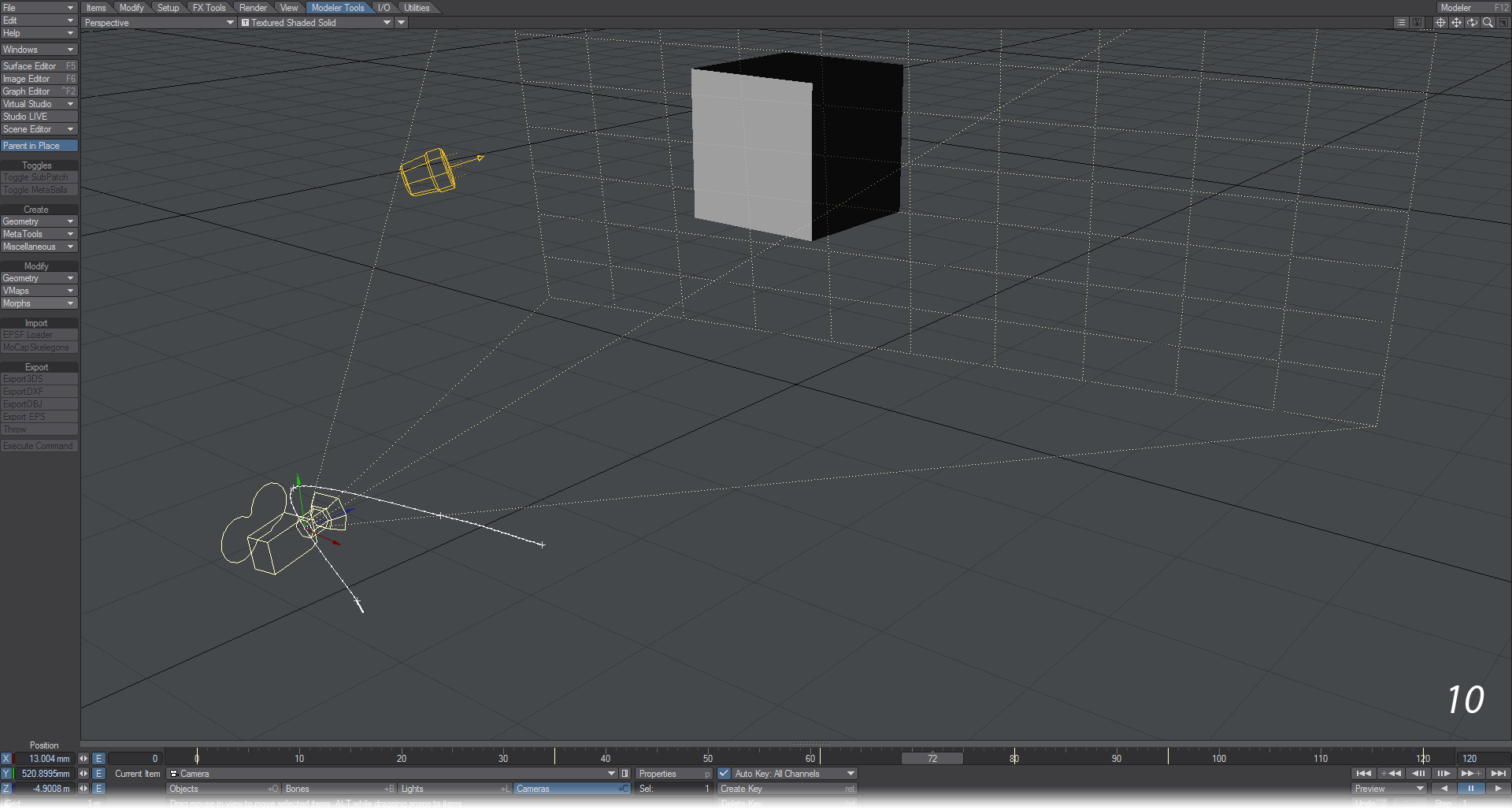
- Start Layout and check to see if Auto Key: All Channels is enabled at the bottom of the interface window. Add a cube by clicking on the Modeler Tools > Create > Geometry > Cube button and accept the default entries by hitting the OK button. The cube will appear at 0, 0, 0.

- Click in an empty part of the viewport and move the mouse. You will see the cube moves since it is the selected object. If you wish to restrict movement to an axis, hit Ctrl Z to undo your move and click and hold on the red arrow indicating the X axis. Drag the cube over to the left side of the screen.
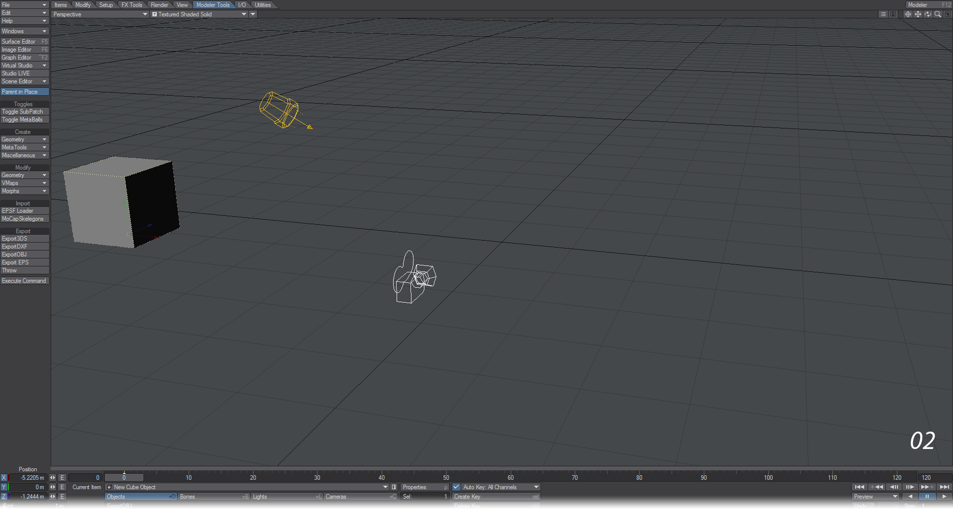
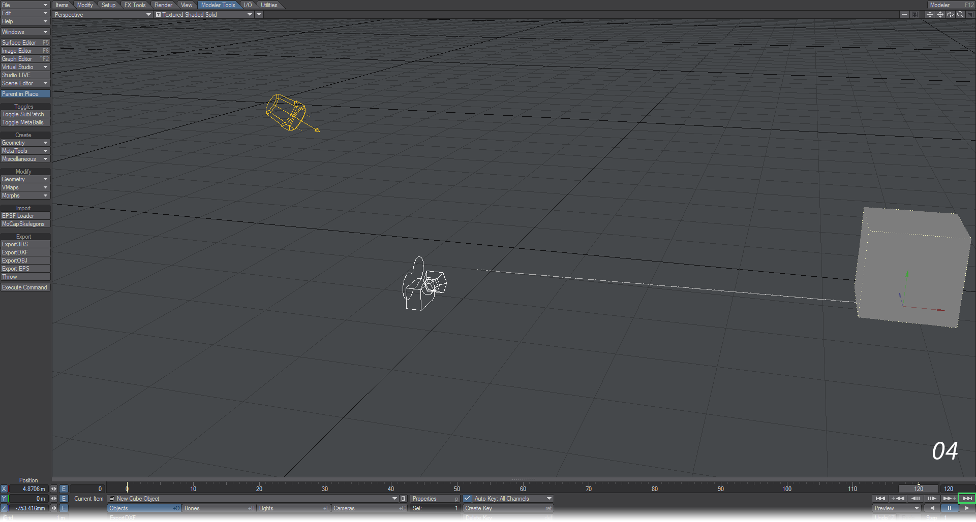
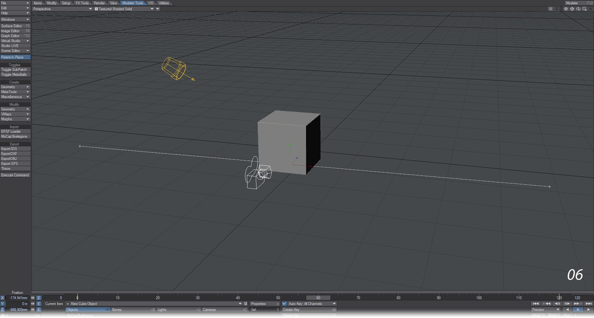
- Move the slider at the bottom of the Layout viewport to the end of the slider range - it will be at frame 120 by default. You can also do this by clicking on the rightmost button of the transport controls under the viewport.
- Move the cube over to the right edge of the viewport, either by the X axis arrow or just freehand in the viewport. You will see two things. The first is that there’s a yellow line on frame 0 in the timeline under the Layout viewport (there’s also one under the slider at frame 120 now, but it won’t be as visible), the second is that there’s a gray dotted line marking some of the path that the cube is taking. If you were to count the dots when the cube is at frame 60 by hand, you would see that there were 120 dots - 60 in front, 60 behind, but just take our word for it. These mark frames along the way.
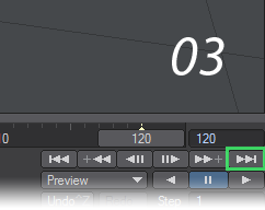
- If you hit the play button just under the right-hand side of the Layout viewport you will now see your cube moving across the screen and starting again when the slider reaches the end of the timeline. Congratulations! You’ve made an animation. It’s not exactly Disney caliber, but it is an animation.
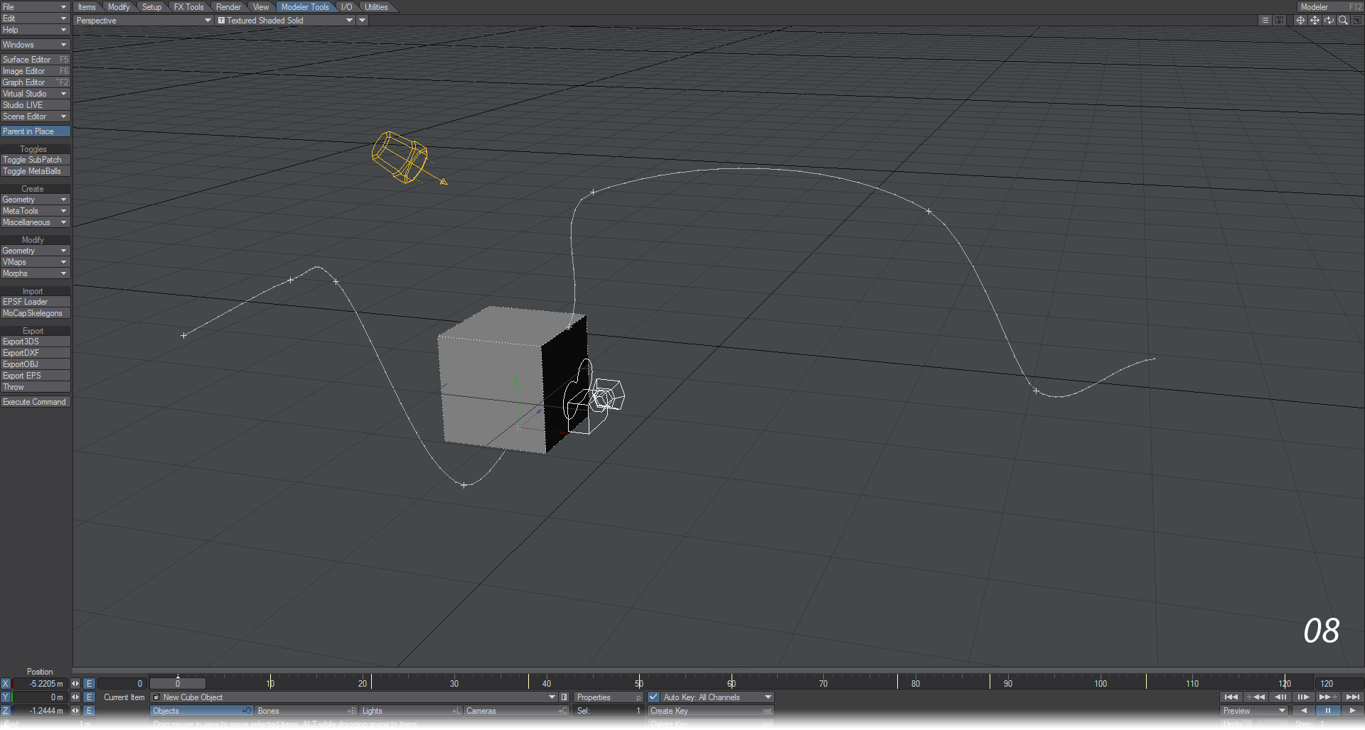
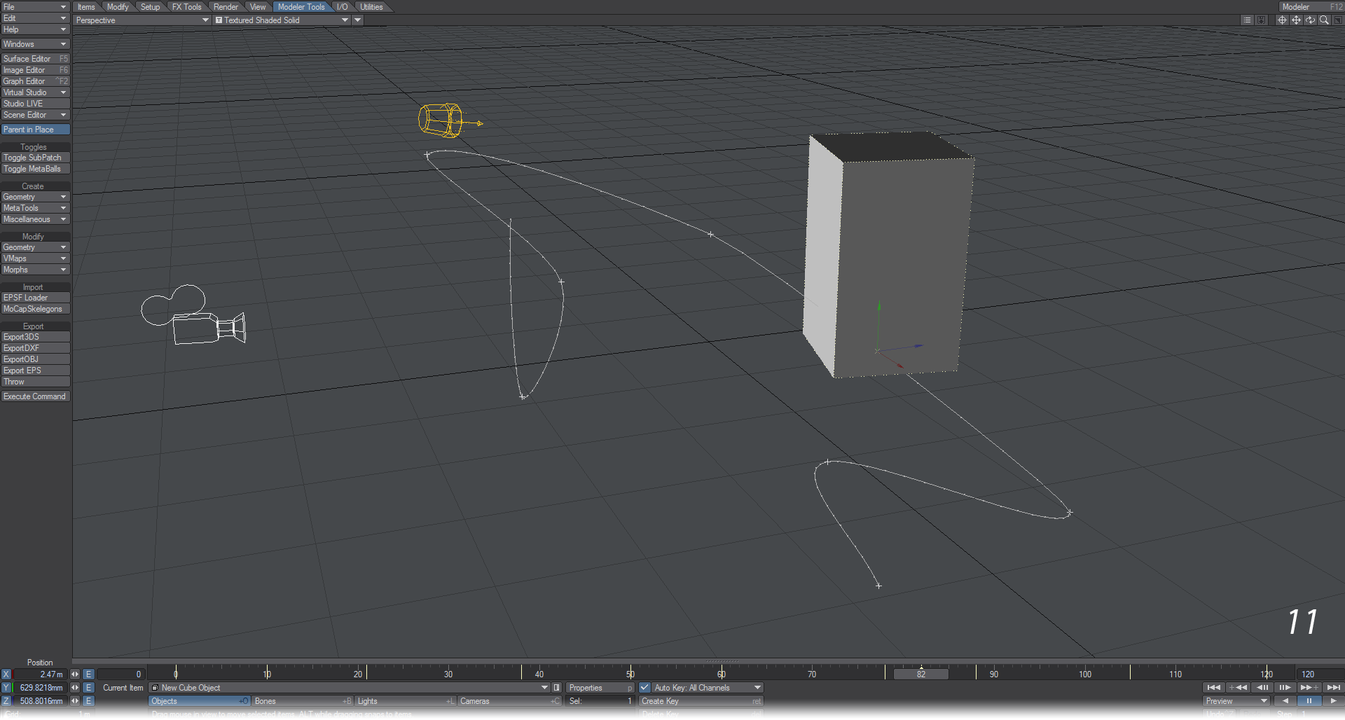
- To make it slightly more interesting, stop the playback by hitting the pause button. Move the timeline slider to the middle of the timeline.
- Move the null up to the top of the viewport. You can do this by grabbing the green arrow pointing upwards from the null, or by using the right mouse button anywhere in the viewport. You will see the motion path change to match the new keyframe. Now when you press play again, you can see that LightWave has taken note of your changes and made the appropriate in-between frames for the motion to proceed smoothly.

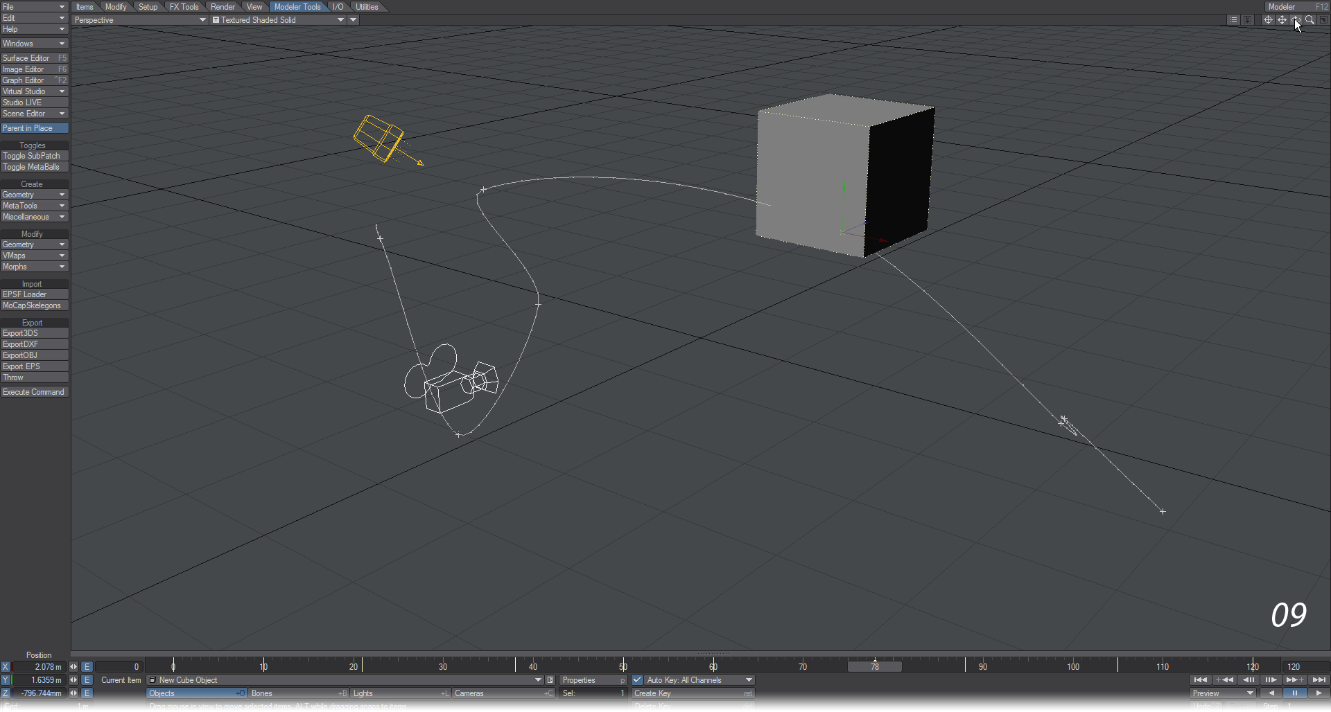
- Stop playback by hitting the Pause button and go through your scene adding more keys as you go. Create a real roller-coaster ride for the Cube to take.
- When you want to check the null’s motion path, press play. When your viewport is in Perspective mode, if you use the navigation controls at the top right of the viewport, you can see how the animation looks from any angle. See something you don’t like? Press pause, move the timeline slider to the frame you want to change and move the cube.
- All items in a LightWave scene can have independent keyframes - while your cube is getting sick on its roller-coaster ride, you can have the light in the scene changing direction and the camera following it around to make it even more disoriented. Even better, just because you’ve keyframed an object’s heading, there’s nothing to say that you can’t keyframe its pitch and bank on different frames.
- Go back to our short tutorial and get everything - and I mean everything: cube, camera, light - moving. Don’t forget that in addition to the Move tool you used to reposition the null, you also have the Rotate tool (keyboard shortcut: Y ) and the Size and Stretch tools (keyboard shortcuts: Shift +H and H). You’ll find all these tools on the Modify Tab or you can just roll the mousewheel. We’re not looking for great art, just trying to get you used to how things work.
Normally speaking, LightWave doesn’t work in seconds because motions tend to be too quick and seconds too coarse a measurement. It works in frames - there are 25 to a second in PAL and 30 frames to a second in the NTSC TV system, HDTV is more complicated, varying between 24 - 60 fps. For film work, there are 24 frames to a second. If you’ve left your time settings at standard they will be at 30 fps and you have created four seconds of animation.
Keep working on your simple animation until you start to feel the cube’s pain at being forced to ride the roller-coaster one more time… This is easy and you’ll be glad you’ve practiced before things start getting harder.
Navigating a Scene

Just under the Layout viewport (or viewports) is the frame slider that we’ve already used for our exciting null animation. Although its main action is obvious, you also have the ability to change the range shown and also to pan through this range easily. To scrub through the frames you can move the slider with the mouse or you can use the cursor keys.
Left and Right move you through the frames one at a time, and holding down the Shift key at the same time moves you to the previous or next keyframe. If you hold down the Alt key while you move the slider with the mouse you will pan the frame range – this means that you will keep the same number of frames on the slider, but the start and end points will change accordingly. If, for instance, you had a 500 frames long animation, the amount of action would cause the detail in the frame slider to be confused. But if you set the end frame to a 100, you can then pan through the other 400 frames of your animation, so this 100 frames could show the range between 0-100, or 357-457, as you like.
You can also jump to a specific frame in your scene by hitting the F key on the keyboard, which will bring up a requester where you can enter a frame number.
Playing a Scene
![]()
Under the transport controls for the scene, you will see two playback arrows and a Pause button, and under that a Step counter. The playback arrows allow you to playback the scene in either direction while the step counter allows you to set how many of the scene’s frames you wish to see played back. Setting this counter to 1 will play every frame, setting it to 2 will play every other frame, and so on.
Make sure your scene is not playing back before you move anything. If you have AutoKey on, you will end up with keyframes all through the animation.
Your playback speed will vary depending on the complexity of your scene, object display mode, system capabilities and so on. Reducing the size of your Layout window can dramatically increase playback speed.
If the Hub active, you can modify an object in Modeler even while your scene is being played back in Layout and the object will automatically update to reflect the changes you make.
Creating Keyframes
As we’ve already learned, objects are always loaded at the Origin. This is the center of Layout’s grid: 0, 0, 0 and every new item will have a default keyframe for frame 0 here. If you never create another keyframe for an item, it will stay at this default location throughout the animation.
Frame 0 is the default starting point, but you can create keys at frames less than 0, if you need to.
We used Autokey in the tutorial at the start of this section, but if we turn it off we will need to set keys by pressing the Return key twice. A window appeared but was dismissed by us hitting the return key the second time. Let’s go in for a closer look at this window.
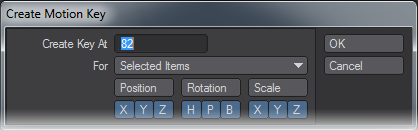
By default the Create Key At field will contain the current frame. You can change the frame number to create the key - using the animation channel values for the current frame - at a different frame by entering a different frame number here. This is a good way to copy a keyframe. You can also re-pose your item and create a new key over an old one.
The For pop-up menu has several options. You can create keys for:
Selected Items - All items that are selected, which will always include the current item. Generally, this will be the one you use the most.
Current Item Only - Only the current item, even if others are selected.
Current Item and Descendants - The current item and any child items.
All Items - All items in the scene. Beware that this is not limited to just items of the same type. A key will be created using the current Animation Channel settings for all objects, bones, lights, and cameras.
The dialogs for creating motion keyframes for scene items have three rows of Toggle buttons. This lets you create animation channel keys independently. The Position, Rotation and Scale buttons allow a row to be turned on or off with one click. All channels are enabled by default and their state is remembered.
Keys created using the Create Motion Key dialog use the Graph Editor’s Default Incoming Curve type, discussed here. Generally, we suggest you use TCB Splines and not Bezier Splines. Bezier tangents are determined at the moment of creation and don’t automatically adjust as new keys are created. This can cause awkward movement through keys.
Creating and Modifying Keys Automatically
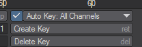
To automatically create or modify keys you must activate the Auto Key option on the main interface. This is the global on/off switch for automatically creating keyframes. It works in conjunction with the Auto Key Create setting (General Options Tab of the Preferences Panel).
Auto Key is a time-saving feature for advanced users and can be very useful for quickly roughing out a motion path; however, beginners may want to stick with creating keys manually.
Make sure you are always aware of the status of Auto Key and Auto Key Create. These options can result in an animation with extraneous keyframes.
The Auto Key function has been refined to allow quicker access to the various modes it can operate in. Previously this feature was hidden away in the Options panel, but is now located directly on the main interface in Layout. The Auto Key preference in the Options panel now only serves as a default startup preference.
An option also appears in the Auto Key popup menu called Auto Key: Existing. This mode was available before but was somewhat hidden; it has now been made much clearer which Auto Key mode you are in. The checkbox is now a visual indicator as to when Auto Key is active and when it’s completely off. Auto Key now has the following modes:
Auto Key: Off
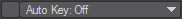
Automatic Keyframing is completely off, no new keyframes will be created or existing ones modified.
Auto Key: Modified

New keyframes will be created/modified, but only on the channels you edit. E.g. If you only move an item, keys will be created/modified only for the translation channels you change, but not for rotation or scale.
Auto Key: All Channels

New keyframes will be created/modified on ALL channels regardless of whether you only move, rotate or scale an item.
Auto Key: Existing

Only existing keyframes will be adjusted, no new keys will be ever be created, this is to allow tweaking of keys without fear of ever creating new ones. In previous versions of LightWave this mode was available when Auto Key Create Default in Options was set to Off, but the Auto Key button in Layout was active. Now you just need to select this option.
Auto Key: Fixed

Keys will only be placed at the Auto Key Fixed Frame set in the field below the pop-up menu. Best used with static items that have no motion paths.
Note that the Autokey indicator at the bottom of Layout works in a similar manner to how the original Autokey on/off button did. For your Autokey preferences to be saved, you still need to visit the Options panel. This setting is not scene-specific.
Editing Motion Paths Directly in a Viewport
You can also move an item’s motion path directly in a viewport using the Move Path tool (Modify > Motion Path > Move Path).
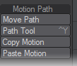
The Move Path tool allows you to shift your completed motion path for an item, keeping all the keys in the same places relatively. Let’s say you had a very complicated scene, it would be useful to be able to move to an empty portion, create the motion path for your object and then move it into place. With Move Path, that’s exactly what you can do.
Move TCB
Another tool in the Modify menu will directly affect your motion path. At the bottom of the Modify list you will find Move TCB. This allows you to set the biases discussed in the Graph Editor section of the manual, but from Layout, rather than having to visit the Graph Editor itself. To use it, move to a keyframe, click on the Move TCB tool and you will notice that the lower left corner now displays T, C, B instead of the more familiar X, Y, Z or H, P, B.
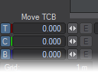
You can enter figures in here for what you wish your TCB settings to be, or you can use the mouse:
- LMB: Moving left and right alters the Tension
- Ctrl+LMB: Moving left and right controls the Continuity
- RMB: Moving left and right controls the Bias
Deleting Keyframes
You delete keyframes in a similar way to how you create them.
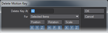
To delete a keyframe:
- Select the item. Normally, you will also go to the keyframe you wish to delete.
- Click the Delete Key button at the bottom center of the Layout interface or press the Del key.
- The Delete Motion Key dialog will appear. It uses all of the same controls previously described for the Create Motion Key dialog.
Delete Motion Key Plugin
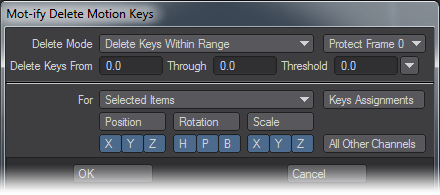
Use the TMP Motify Delete Motion Key generic plugin (Utilities > Additional > Motify) to delete keyframes, clear motions, delete ranges of keys, delete keys within a threshold, and more. Motify can be used to completely replace the built-in Delete Key dialog.
To use Motify:
- Select the item(s) you want to delete keyframes from. Normally, you will also go to the keyframe you wish to delete.
- Run Motify
- Choose a Delete mode.
- Enter a range of keys in the Delete Keys From and Through input fields.
- Enter a Threshold.
- Choose a For mode.
- Enable or disable channels
- Click OK.
Many of the above steps are optional. For example, to simply delete a keyframe at the current time (using the previous For mode), run Motify and click OK.
The For pop-up menu determines which objects will have their keys deleted and has several options. You can delete keys for:
- Selected Items - All items that are selected, which will always include the current item. Generally, this will be the option you use the most.
- Selected Items and Descendants - The selected items and any child items.
- Current Item Only - Only the current item, even if others are selected.
- Current Item and Descendants - The current item and any child items.
- All Items - All items in the scene. Beware that this is not limited to just items of the same type.
The Position, Rotation and Scale buttons allow a row to be turned on or off with one click. Only the selected channels will be processed. You can Shift click to invert a group’s selection state.
The All Other Channels button is a powerful feature, but can cause a lot of damage to your scene if used incorrectly. All non-motion channels will also be processed (the Position, Rotation and Scale buttons still determine if the motion channels are processed). This includes all envelopes applied to those items (like Camera Zoom Factor and Light Intensity), envelopes for applied plugins (such as Morph Mixer channels), and surface envelopes applied in the Surface Editor. Use this feature carefully, especially when deleting keys on multiple items at once.
The About button will open an informational dialog, including a list of keyboard shortcuts.
Delete Mode
The Delete Mode determines what is done to the item’s motion. The default mode, Delete Key, deletes the key at the frame entered in the Delete Keys field From field. Both integer and fractional keyframe values can be entered.
The Threshold field can be used to determine how close a keyframe has to be to the defined frame to be deleted. This is useful for deleting fractional keyframes when Fractional Frames is disabled on the General Options Tab of the Preferences Panel.
- Delete Keys Within Range will delete all keyframes between and including the From and Through frames. The Threshold setting, in this case, will extend the range lower and higher - all keys within the range will be deleted.
- Delete Keys Outside Range will delete all keyframes outside, but not including, the From and Through frames. Threshold is not used in this mode, as it only applies when the end frames are also deleted.
- Delete Keys Before Range deletes all keyframes before, but not including, the From frame. Similarly, Delete Keys After Range deletes all keys after, but not including, the Through frame.
- With Clear Motion , all existing keyframes will be deleted. This will only clear the channels marked at the bottom of the dialog.
If all keyframes become deleted in any of these modes, a new default keyframe is created at frame 0 with a position and rotation of 0.0 on all axes, and a scale of 1.0.
Threshold
Threshold determines how close a keyframe has to be to the From and Through frame numbers in order to be deleted. The default value of 0.0 means that the key must exactly match the frame numbers entered. A value of 0.1 means that any keyframe within 0.1 frames will be deleted. For example, if you are trying to delete keyframe 20 with a Threshold of 0.1, all keys between 19.9 and 20.1 will be deleted. A value of 0.5 can be used to ensure that any fractional keys between the current frame and the next or previous frames are deleted without going into the domain of the next keyframe. The small pop-up menu to the right of the Threshold input field contains a number of reasonable presets values.
Protection
The Protection pop-up menu can be used to ensure that certain important keyframes are not deleted. This is especially useful when using the Delete Keys Outside Range or Clear Motion modes, where deleting all keyframes could ruin your scene or destroy your character’s bone setup and IK poses.
- No Protection means that no keyframes will be protected from deletion. This allows you to delete any keyframe.
- Protect Frame 0 will ensure that no keys at frame 0 are deleted. Similarly, Protect Neg & 0 will protect frame 0 and all negative keyframes.
- Protect First Key and Protect Last Key will keep you from deleting the first or last key in the channel, respectively.
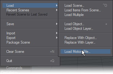
Saving and Loading Motion Files
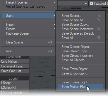
To save the selected item’s motion path to a file, choose File > Save > Save Motion File. Use the filename extension .mot when saving a motion file. Mac users should note that this extension is not automatically added - you must type it as part of the file name and then save the file. To load a saved motion file and apply it to the selected item, choose File > Load > Load Motion File.
Modeler’s Path Extrude and Path Clone commands use these files to execute their operations.
DopeTrack
BioVision Motion Capture Support
LightWave provides a couple of plugins to support the BioVision (BVH) motion capture file format. The MoCap_BVH_Setup generic Layout plugin (File > Import > MoCap_BVH_Setup) reads a BioVision BVH file, creates bones, and applies the motion capture data to them. For any use of Motion Capture files, you will need to have AutoKey (Shift F1) enabled.
Set Start Frame Offset to the frame you want the motion to begin.
Bone Scale Factor allows you to set a scale for your object from the start and may need some repeated experiments to get close to the scale of your object. Often BVH files come in at an extremely large scale. As a start, try a scale of 0.1.
The Bone Name Postfix is simply a number appended to the end of all of the bone names (e.g., LeftKnee_1).
After you run the plugin, replace the top null (in the created bone hierarchy) with the object to be animated. You could also use the Use Bones From Object feature on the Bones Properties Panel.If you need to change the initial resting position of bones, make sure you reset their rest positions (use the r key). You’ll probably need to adjust some of the individual bone properties after you run the plugin.
Applying motion capture to a LightWave object is an arduous process fraught with difficulties but yields good results.
MoCapSkelegons is a Modeler plugin that creates skelegons in Modeler that match the initial rest position of the Biovision BVH data. Use it to determine the correct scale, position, etc. for your object mesh. This object can then be used with the bones created using the MoCap_BVH_Setup generic plugin in Layout.
Motion Preview
There is also a custom object plugin that can be used to preview BioVision motion data. The preview is fast and accurate. Use it to determine if there were any errors in the motion conversion.Simply add the MotionCapturePreview custom object to a null object on the Object Properties Panel. (If you run the MoCap_BVH_Setup generic Layout plugin, a null called “MotionCapturePreviewNull” will automatically be added to the scene with the custom object plugin already applied.)
Keyframer
Modify
Now we shall examine the Modify tab:
Translate Group
Rotate Group
Transform Group
Coordinate System
The Coordinate System setting (Modify > General > Coord System) affects the Move, Rotate, and Move Pivot Point tools.
World (default keyboard shortcut Shift F5)
World allows easy movement based on the world axes, even for items deep within a hierarchy that contain rotated parents.
Parent (default keyboard shortcut Shift F6)
Parent is for movement based on the axes of an item’s parent(s). If an item has no parent then this setting is equivalent to World.
Local (default keyboard shortcut Shift F7)
Local is for movement based on an item’s own axes (such as dollying a rotated camera along its view direction). For un-rotated items it is equivalent to Parent. Local can be temporarily activated by holding Ctrl.
Example
Below, we have rotated a null and then parented a distant light to it. The Show Handles option, discussed later is also active for illustration purposes, as it is by default. The handles will line up with the movement axes that would be used if you dragged your mouse.
Local

Parent
World
Note how with World, the handles line up with the lines on the grid. With Parent, the handles line up with the rotated (parented) null. Finally, with Local, the handles line up with the distant light’s rotation.
The Position and Rotation Coordinate System settings are independent. To change the system, select either the Move or Rotate tool first.
One thing to remember about Local and World rotation is that they are only for interactive manipulation. Internally, the Parent system is always used since it’s the only one that can encode absolute rotation values. This will affect how an item’s orientation is interpolated between two keyframes. As such, rotating the pivot point might still be useful in some situations.
Avoiding Gimbal Lock
Gimbal lock normally occurs after you rotate an item 90 degrees on its pitch using the Parent coordinate system. Once this has occurred, rotating the object about either its heading or its bank axis gives you the same result-you have lost the ability to rotate about the object’s local heading. Gimbal lock is commonly a problem with bones in a hierarchy. By nature, bones have a starting position that is often rotated 90 degrees on their pitch, like bones in the arm of a human figure. You can avoid Gimbal lock by rotating using the Local coordinate system.
Reset
You can quickly reset position and rotation to their initial states by selecting the item, activating the channel you wish to reset (i.e., Move, Rotate, Size, and other tools), and then clicking Modify > Reset. You can reset individual channels without being in the mode by hitting Reset Position, Reset Rotation or Reset Scale and all channels with Reset All.
If you plan to move a pivot point, you should reset the item’s position and rotation first.
Reset is not an undo feature, although it can sometimes work similarly. Resetting restores the state for the selected channels to what it was when the item was first loaded or created.
If you have Position or Rotation axes deactivated, Reset will have no effect on those settings.
Light Intensity
(default keyboard shortcut Ctrl H)
Selecting a light, or several for that matter, and using this tool allows you to adjust light intensity interactively by holding down the LMB and moving the mouse left and right. Feedback is given down in the bottom left corner as usual. If you adjust more than one light at once, the feedback area reports how one is being adjusted, but all that are selected are adjusted equally. Make sure you multi-select with the Shift key rather than making a banding box.
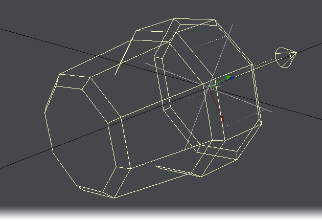
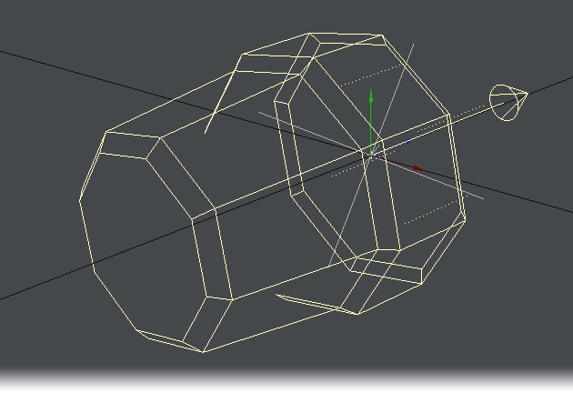
Sliders
(default keyboard shortcut Ctrl D)
Sliders (Modify > Tools > Sliders) are slider gadgets that are displayed over viewports. An individual slider is tied to a specific animation channel. A slider will indicate the current value of a channel and also let you interactively adjust that channel value. Sliders are useful for all kinds of animations, especially character animations. A good example can be an animated hand, with multiple bone movements for multiple fingers.

To use sliders in a scene:
Add the Sliders custom object (Object Properties Panel) to any object.
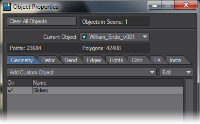
To display and interact with the sliders, choose Modify > Tools > Sliders. The sliders for the last current object (with the Sliders custom object) will be editable when the Sliders tool is active. Keep this in mind if you have more than one object with the Sliders custom object.
Remember, as with all Layout tools, you’ll need to select another tool (Move, Rotate, etc.) to deactivate the Slider tool.
To configure your sliders:
Open the Sliders Custom Object settings dialog from the Object Properties Panel.
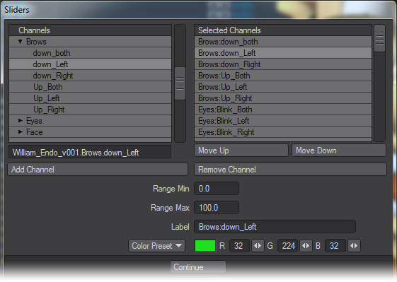
The left window (Channels List) will list all of the channels in the scene. To attach a slider to a channel, simply select the channel in the left window and double click or click the Add Channel button. Selected channels in the right window can be removed with the Remove Channel button.
The Range Min and Range Max settings define the interactive range of the slider. The underlying channel can go beyond these values, but the slider’s range of control and feedback will be limited to this range. If the underlying channel goes outside the range, the slider value will turn red.
Clicking on the slider handle will immediately change the channel to the slider’s corresponding value.
The description Label will default to the channel name, but you may edit that if you desire. You can also set the color used for the slider with the Color preset pop-up menu or specific RGB values.Working with OpenGL Sliders:

There are three controls along the top. Drag the far-left one to move the slider group. The Envelope (E) button will display the Graph Editor with the associated channels in the curve bin. The right/left arrowhead (<>) button can be dragged to scale the size of the slider group. The arrowhead button on the right will minimise/maximise the slider display.
In the individual slider entries, the handle can be grabbed to slide to any value in the range set up and the arrows at the right end are to jump from keyframe to keyframe.
To simplify using sliders, use the Add Slider Bank generic plugin command (Not assigned to the interface by default). It will add a null object, apply the sliders custom object to it, and open the sliders interface, all in one step.
Spline Displacement
Spline Displacement is not a new tool. It used to be called SplineControl
The Spline Displacement Tool (Modify >Tools > Spline Disp Ctrl) is a simple way to animate hoses, tentacles, etc. using a spline with control handles. This tool will create a spline the length of the object with a user specified amount of control points that can be used to deform an object.
To use Spline Displacement
- Select the object that you would like to animate with Spline Displacement.
- In the Object Properties window, Primitive tab, Modifier section, choose Spline Displacement from the Add Modifier Dropdown menu.
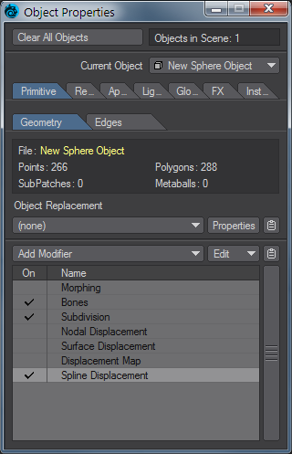
- Double-click Spline Displacement to open its interface.
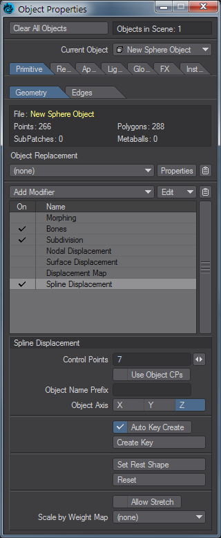
- Choose how many Control Points you want (you can change this later, but doing so might lose any animation set). The slider will set a minimum of 5 and a maximum of 256, but a minimum of 3 can be typed if desired.
- Use the Spline Displacement button (Modify > Spline Disp Ctrl) to activate and move the nodes around.
Spline Displacement Options

- Control Points - This field will determine the number of control handles that will be generated.
Each control point will be numbered starting from 0. This number will appear in OpenGL.
- Use Object CPs - Uses nulls with the names given in Object Name Prefix placed in scene as control points for the spline displacement
Object Name Prefix - Prefix for naming nulls for spline displacement
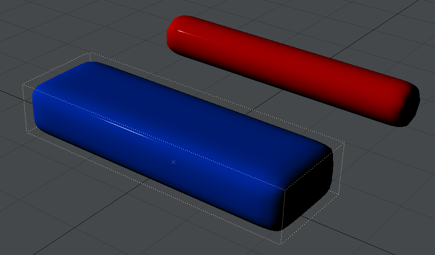
Spline Displacement can use other objects as controllers for the displacement. Here we look at moving our bar with null objects.
- Object Axis - Defines the axis the control spline will be drawn on.
- Auto Key Create - Similar to Layout’s standard Auto Key in that it will automatically create a keyframe as you move a control point. The only difference is that it will always create when on frame zero regardless of whether or not this option is active.
- Create Key - When Auto Key Create is not active use this to create a keyframe.
Hitting Enter on the keyboard will not set a keyframe for a control point.
- Set Rest Shape - Use this to change the default rest position of the control points in relationship to the object.
- Reset - This function works like undo, however instead of just undoing the last move it will reset all control points to their rest position.
- Allow Stretch - When this option is activated the object is able to be stretched past its original scale.
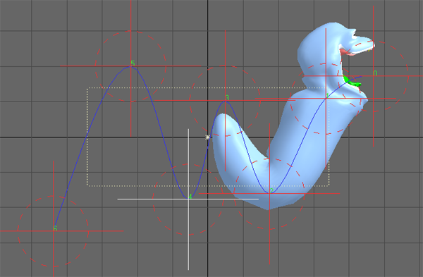
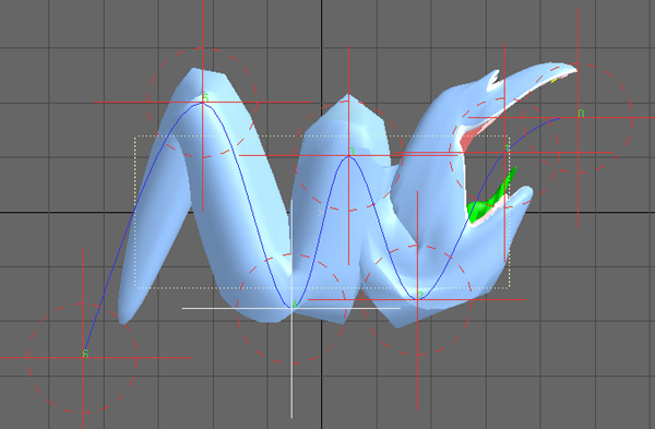
Left: Allow Stretch OFF, Right: Allow Stretch ON
- Scale by Weight Map - This option will use the Weight Map selected and only deform that area of the mesh.
Edit Tool
(default keyboard shortcut Ctrl E)
The Edit tool (Modify > Tools > Edit Tool) activates the ability to edit points on dynamic objects and particles. You will be able to visually see that you’re in Edit Mode in the viewport. All the points that make up the object will become highlighted and all the Edit tool functions will become active.
For more information about the Edit tools and some of its options, see the Dynamics and Particles sections.
MDD Multi-Loader
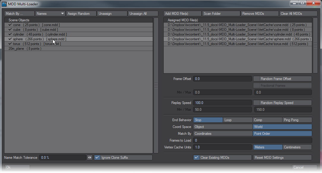
The MDD workflow is central to using LightWave in a multi-product pipeline, or to enforce consistency when network rendering. LightWave has long been able to save and load MDD files and this new window makes them much faster and easier to apply scene-wide. On the left side of the window are presented the objects in your scene with their point counts. The list on the right will hold the MDD files you load using the Add MDD file(s) or Scan Folder buttons. Once you have objects on the left and MDDs on the right you can either assign by hand, clicking on the object in the left list first, then the MDD; or you can use one of the automatic matching routines:
- Names - Matches the MDD filename to the object name in Layout
- Points - Matches the object pointcount with the MDD’s pointcount (MDDs with pointcounts different to the objects they are aplied to don’t give predictable results)
- Points & Name - Will only match the MDD to the object if both Name and pointcount are identical (the most secure)
- Points or Name - Tries to match pointcounts first, then name if the first attempt finds no matches
Following the Match By... options there are three other buttons.
- Assign Random - this will randomly choose an MDD in the right list to assign to the objects on the left list.
- Unassign - This removes the MDD assigned to the object. You can also click in a blank area in the MDD list
- Unassign All - This gives a warning before removing all MDD assignments to the object list
All of the Name options respect the Name Match Tolerance percentage field under the left object name field. At its default 0% assigning MDDs is based on a strictly exact name match. Increasing this percentage will match more and more items to 100% where everything will be matched.
To the right of this field is Ignore Clone Suffix. This is checked by default since you often need to assigned MDDs to cloned objects. If you wish to control which MDDs get assigned to which of your cloned objects uncheck this button.
Once matched a tick will show by the object name in the left list. Clicking on an object with an MDD assigned will highlight the MDD it has been assigned in the right list. You can assign a different MDD by clicking on it in the right list and you can Remove MDDs by clicking the button with the same name, or Clear All MDDs by clicking the button to its right. This presents a warning before clearing the entire list of MDDs from the right list.
Under the MDD list on the right side of the window are the same options you will find in the MD Reader you will have used previously in LightWave for going through each object in the scene one by one. There are Random Frame Offset and Random Replay Speed buttons with ranges beneath each to allow you to apply some randomisation automatically across MDDs rather than needing to each individually.
The last two buttons are:
- Clear Existing MDDs - This clears MDDs already assigned to the objects in the left list before applying those you have chosen in this window
- Reset MDD Settings - This button merely resets the MDD settings in the lower right half of the MDD Multi-Loader window back to their defaults if you have made changes you don’t like
When you hit OK, the MD Readers are applied to the objects as in previous versions of LightWave.
Example - MDD Loader
Align and Distribute
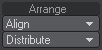
Located on the Modify Tab > Arrange Group in Layout, these small but useful tools make aligning and spacing items equally in Layout easier. The Align tools work in much the same way as the Align to Last Point tools in Modeler, but for any Layout Scene items. To use them select the items you wish to align, then select the last item to which you want to align the other items. From the Align menu choose which axis (X/Y/Z) you wish to align against. Once clicked, all the items you selected will be aligned to the last item’s axis you picked.
To distribute, or equally space items, you don’t need to worry about the selection order, simply select the items you wish to equally space between each other, and choose the axis (X/Y/Z, or All Axis) you want to space the items along.
Please Note: Due to the way Generic Scripts operate in Layout, these tools will not contribute to any Undo. Make sure you save your scene if you are unsure whether you want to keep the changes, or you will lose the original positions of the items.
Nodal Metalink
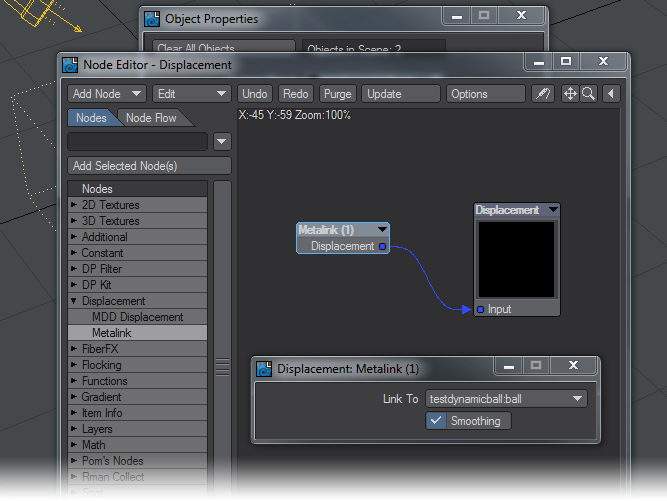
Users that have been LightWave artists for a long time will be familiar with the Metalink functionality for creating a simulation with a low polygon mesh and then using that simulation to drive the motions of a higher quality mesh. LightWave 11.5 introduced a nodal way of metalinking objects together. To use it, simply visit your high polygon mesh’s Object Properties window, the Deform tab and click Edit Nodes. Choose Displacement > Metalink and select the low polygon mesh you have used for the dynamics simulation.
The Metalink node can’t handle a lowpoly SubPatch mesh that was used for dynamics simulation linked to a highpoly SubPatched or polygonal object unless the lowpoly SubPatched object is set to a Display level of 0, but this shouldn’t prove much of a limitation.
LightWave's many tools for animation include not only the FK and IK sort, but also more procedural animation types, like Spline Control and Raycasting.
- Rigging
- Animation
- IK Boost
- Spline Displacement
- Motion Mixer
- Ray Cast Geometry
- Spline Control
- Instancing reference